key Lancia Voyager 2012 Owner handbook (in English)
[x] Cancel search | Manufacturer: LANCIA, Model Year: 2012, Model line: Voyager, Model: Lancia Voyager 2012Pages: 344, PDF Size: 3.95 MB
Page 60 of 344

Mass GroupSeating Position (or other site)
Front Passenger Rear Outboard Rear Center Intermediate
Outboard Intermediate
Center
Group 0 - Up to 10 kg XUUUX
Group 0+ - Up to 13 kg XUUUX
Group 1 - 9 to 18 kg XUUUX
Group II - 15 to 25 kg XUUUX
Group III - 22 to 36 kg XUUUX
Key of letters used in the table above:
U = Suitable for “universal” category
restraints approved for use in this
age/weight group.
UF = Suitable for forward-facing
“universal” category restraints ap-
proved for use in this mass group. L = Suitable for particular child re-
straints given on attached list. These
restraints may be of the “specific ve-
hicle”, “restricted” or “semi-
universal” categories.
B = Built-in restraint approved for the
age/weight group.
X = Seat position not suitable for chil-
dren in this age/weight group.
54
Page 61 of 344

Vehicle ISOFIX Positions Chart
Mass Group Size
Class Fixture Front
Passenger Rear
Outboard Rear
Center Intermediate
Outboard SSnG Intermediate
Center LUX. Quad Other Sites
Carrycot F ISO/L1 X X X IUF* IUF
X
G ISO/L2 X X IUF** IUF* IUF X
(1) X X X XX X
0 — up to
10 kg E ISO/R1 X X IUF** IUF IUF
X
(1) X X X XX X
0+ — up to 13 kg E ISO/R1 X X IUF** IUF IUF
X
D ISO/R2 X X IUF** IUF IUF X
C ISO/R3 X X IUF** IUF IUF X
(1) X X X XX X
I – 9 to 18 kg D ISO/R2 X X IUF** IUF IUF
X
C ISO/R3 X X IUF** IUF IUF X
B ISO/F2 X X IUF** IUF IUF X
B1 ISO/F2X X X IUF** IUF IUF X
A ISO/F3 X X IUF** IUF IUF X
(1) X X X XX X
II – 15 to
25 kg (1) X X X
XX X
III – 22 to 36 kg (1) X X X
XX X
Key of letters used in the table above:
(1) For the CRS which do not carry
the ISO/XX size class identification
(A to G), for the applicable mass
group, the car manufacturer shall in-
dicate the vehicle specific ISOFIX child restraint system(s) recom-
mended for each position.
IUF = Suitable for ISOFIX forward
child restraint systems of “universal”
category approved for use in the mass
group.IL = Suitable for particular ISOFIX
child restraint systems (CRS) given in
the attachment list. These ISOFIX
CRS are those of the “specific ve-
hicle”, “restricted” or “semi-
universal” categories.
55
Page 95 of 344
NOTE:
This may not be the last number
dialed from the Uconnect™
Phone.
Call Continuation
Call continuation is the progression of
a phone call on the Uconnect™ Phone
after the vehicle ignition key has been
switched to OFF. Call continuation
functionality available on the vehicle
can be any one of three types:
After the ignition key is switched toOFF, a call can continue on the
Uconnect™ Phone either until the
call ends, or until a vehicle specific
time expires, or until the vehicle
battery condition dictates cessation
of the call on the Uconnect™ Phone
and transfer of the call to the mo-
bile phone.
After the ignition key is switched to OFF, a call can continue on the
Uconnect™ Phone for a certain du-
ration, after which the call is auto-
matically transferred from the
Uconnect™ Phone to the mobile
phone. An active call is automatically
transferred to the mobile phone af-
ter the ignition key is switched to
OFF.
UCONNECT™ PHONE
FEATURES
Language Selection
To change the language that the
Uconnect™ Phone is using:
Press the
button to begin.
After the “Ready” prompt and the following beep, say the name of the
language you wish to switch to
(English, Dutch, French, German,
Italian, or Spanish, if so equipped).
Continue to follow the system prompts to complete language se-
lection.
After selecting one of the languages,
all prompts and voice commands will
be in that language.
NOTE:
After every Uconnect™ Phone lan-
guage change operation, only the
language-specific 32-name
phonebook is usable. The paired phone name is not language-
specific and is usable across all
languages.
For command translations and alter-
nate commands in supported lan-
guages, refer to “Commands” in
“Voice Command System Operation”.
Emergency Assistance (for
versions/markets, where
provided)
If you are in an emergency and the
mobile phone is reachable:
Pick up the phone and manually
dial the emergency number for
your area.
If the phone is not reachable and the
Uconnect™ Phone is operational, you
may reach the emergency number as
follows:
Press the
button to begin.
After the “Ready” prompt and the following beep, say “Emergency”
and the Uconnect™ Phone will in-
struct the paired mobile phone to
call the emergency number.
89
Page 96 of 344
NOTE:
The default number is 112. Thenumber dialed may not be ap-
plicable with the available mo-
bile service and area.
If supported, this number may be programmable on some sys-
tems. To do this, press thebutton and say “Setup”, fol-
lowed by “Emergency”.
The Uconnect™ Phone does slightly lower your chances of
successfully making a phone
call as to that for the mobile
phone directly.WARNING!
To use your Uconnect™ Phone Sys-
tem in an emergency, your mobile
phone must be:
turned on,
paired to the Uconnect™ System,
and have network coverage.
Breakdown Service (for
versions/markets, where
provided)
If you need Breakdown service:
Press the
button to begin. After the “Ready” prompt and the
following beep, say “Breakdown
service”.
NOTE:
The Breakdown service number
has to be setup before using. To
setup, press the
button and say
“Setup, Breakdown Service” and
follow prompts.
Paging
To learn how to page refer to “Work-
ing with Automated Systems”. Paging
works properly except for pagers of
certain companies which time out a
little too soon to work properly with
the Uconnect™ Phone.
Voice Mail Calling
To learn how to access your voice
mail, refer to “Working with Auto-
mated Systems”.
Working With Automated Systems
This method is used in instances
where one generally has to press num-
bers on the mobile phone keypad
while navigating through an auto-
mated telephone system.
You can use your Uconnect™ Phone
to access a voice mail system or an automated service, such as a paging
service or automated customer ser-
vice. Some services require immediate
response selection. In some instances,
that may be too quick for use of the
Uconnect™ Phone.
When calling a number with your
Uconnect™ Phone that normally re-
quires you to enter in a touch-tone
sequence on your mobile phone key-
pad, you can press the
button
and say the sequence you wish to en-
ter followed by the word “Send”. For
example, if required to enter your PIN
followed with a hash, (3 7 4 6 #), you
can press the
button and say, “3
7 4 6 # Send”. Saying a number, or
sequence of numbers, followed by
“Send”, is also to be used for navigat-
ing through an automated customer
service center menu structure, and to
leave a number on a pager.
You can also send stored Uconnect™
Phonebook entries as tones for fast
and easy access to voice mail and
pager entries. To use this feature, dial
the number you wish to call and then
press thebutton and say
“Send.” The system will prompt you
90
Page 97 of 344
to enter the name or number and say
the name of the phonebook entry you
wish to send. The Uconnect™ Phone
will then send the corresponding
phone number associated with the
phonebook entry, as tones over the
phone.
NOTE:
You may not hear all of the tonesdue to mobile phone network
configurations; this is normal.
Some paging and voice mail sys- tems have system time out set-
tings that are too short and may
not allow the use of this feature.
Barge In — Overriding Prompts
The “Voice Command” button can be
used when you wish to skip part of a
prompt and issue your voice com-
mand immediately. For example, if a
prompt is asking “Would you like to
pair a phone, clear a…,” you could
press the
button and say, “Pair
a Phone” to select that option without
having to listen to the rest of the voice
prompt. Turning Confirmation Prompts
On/Off
Turning confirmation prompts off
will stop the system from confirming
your choices (e.g., the Uconnect™
Phone will not repeat a phone number
before you dial it).
Press the
button to begin.
After the “Ready” prompt and the following beep, say:
� “Setup Confirmations Prompts On”
� “Setup Confirmations Prompts Off”
Phone And Network Status
Indicators
If available on the radio and/or on a
premium display such as the instru-
ment panel cluster, and supported by
your mobile phone, the Uconnect™
Phone will provide notification to in-
form you of your phone and network
status when you are attempting to
make a phone call using Uconnect™
Phone. The status is given for network
signal strength, phone battery
strength, etc. Dialing Using The Mobile Phone
Keypad
You can dial a phone number with
your mobile phone keypad and still
use the Uconnect™ Phone (while di-
aling via the mobile phone keypad,
the user must exercise caution and
take precautionary safety measures).
By dialing a number with your paired
Bluetooth® mobile phone, the audio
will be played through your
vehicle's
audio system. The Uconnect™ Phone
will work the same as if you dialed the
number using a Voice Command.
NOTE:
Certain brands of mobile phones
do not send the dial ring to the
Uconnect™ Phone to play it on the
vehicle audio system, so you will
not hear it. Under this situation,
after successfully dialing a num-
ber the user may feel that the call
did not go through even though the
call is in progress. Once your call is
answered, you will hear the audio.
Mute/Un-Mute (Mute Off)
When you mute the Uconnect™
Phone, you will still be able to hear
the conversation coming from the
91
Page 101 of 344
Send Messages:
You can send messages using
Uconnect™ Phone. To send a new
message:
Press the
button.
After the “Ready” prompt and the following beep, say “SMS Send” or
“Send Messages”.
You can either say the message you wish to send or say “List Mes-
sages.” There are 20 preset mes-
sages.
To send a message, press the
button while the system is listing the
message and say “Send.”
Uconnect™ Phone will prompt you to
say the name or number of the person
you wish to send the message to.
List of Preset Messages:
1. Yes
2. No
3. Where are you?
4. I need more direction. 5. L O L
6. Why
7. I love you
8. Call me
9. Call me later
10. Thanks
11. See You in 15 minutes
12. I am on my way
13. I’ll be late
14. Are you there yet?
15. Where are we meeting?
16. Can this wait?
17. Bye for now
18. When can we meet
19. Send number to call
20. Start without me
Turn SMS Incoming Announcement
ON/OFF
Turning the SMS Incoming An-
nouncement OFF will stop the system
from announcing the new incoming
messages.
Press the
button.
After the “Ready” prompt and the following beep, say “Setup, Incom-
ing Message Announcement”, you
will then be given a choice to
change it.
Bluetooth® Communication Link
Mobile phones have been found to
lose connection to the Uconnect™
Phone. When this happens, the con-
nection can generally be reestablished
by switching the phone off/on. Your
mobile phone is recommended to re-
main in Bluetooth® ON mode.
Power-Up
After switching the ignition key from
OFF to either ON or ACC position, or
after a language change, you must
wait at least 15 seconds prior to using
the system.
95
Page 122 of 344

WARNING!
In a collision, you or others in your
vehicle could be injured if seats are
not properly latched to their floor
attachments. Always be sure the
seats are fully latched.
Tailgate Mode
1. Pull release strap “3”, then pull
release strap “4” to rotate the entire
seat rearward.
2. To restore the seat to its upright
position, lift up on the seatback and
push forward until the anchors latch.WARNING!
To avoid serious injury or death,
never operate the vehicle with occu-
pants in the third row seat while in
the tailgate mode.
PLASTIC GROCERY BAG
RETAINER HOOKS
Retainer hooks which will hold plastic
grocery bag handles are built into the
seatbacks of all rear seats and some
front seats. The floor supports the
partial weight of the bagged goods. DRIVER MEMORY SEAT
(for versions/markets,
where provided)
The Memory Buttons 1 and 2 on the
driver's door panel can be pr
o-
grammed to recall the driver's seat,
driver's outside mirror, adjustable
brake and accelerator pedals, and ra-
dio station preset settings. Your Re-
mote Keyless Entry (RKE) transmit-
ters can also be programmed to recall
the same positions when the UN-
LOCK button is pressed.
Your vehicle may have been delivered
with two RKE transmitters. Only one
RKE transmitter can be linked to each
of the memory positions. SETTING MEMORY
POSITIONS AND LINKING
RKE TRANSMITTER TO
MEMORY
NOTE:
Each time the SET (S) button and a
numbered button (1 or 2) is
pressed, you erase the memory set-
tings for that button and store a
new one.
1. Insert the ignition key and turn the
ignition switch to the ON position.
2. Press the driver door MEMORY
button number 1 if you are setting the
memory for driver 1, or button num-
ber 2 if you are setting the memory for
driver 2. The system will recall any
stored settings. Wait for the system to
complete the memory recall before
continuing to Step 3.
3. Adjust the
driver's seat, recliner,
and driver's side-view mirror to the
desired positions.
4. Adjust the brake and accelerator
pedals to the desired positions.
Driver Memory Switch
116
Page 123 of 344

5. Turn on the radio and set the radio
station presets (up to 10 AM and
10 FM stations can be set).
6. Turn the ignition switch to the
OFF position and remove the key.
7. Press and release the SET (S) but-
ton located on thedriver's door.
8. Within five seconds, press and r e-
lease MEMORY button 1 or 2 on the
driver's door. The next step must be
performed within 5 seconds if you
desire to also use a RKE transmitter to
recall memory positions.
9. Press and release the LOCK button
on one of the RKE transmitters.
10. Insert the ignition key and turn
the ignition switch to the ON position.
11. Select “Remote Linked to
Memory” in the Electronic Vehicle In-
formation Center (EVIC) and enter
“Yes”. Refer to “Electronic Vehicle In-
formation Center (EVIC)/Customer-
Programmable Features” in “Under-
standing Your Instrument Panel” for
further information.
12. Repeat the above steps to set the
next Memory position using the other numbered Memory button or to link
another RKE transmitter to memory.
Memory Position Recall
NOTE:
The vehicle must be in PARK to
recall memory positions. If a recall
is attempted when the vehicle is
not in PARK, a message will be
displayed in the EVIC.
To recall the memory settings for
driver one, press MEMORY button 1
on the
driver's door or the UNLOCK
button on the RKE transmitter linked
to memory position 1.
To recall the memory setting for
driver two, press MEMORY button 2
on the driver's door or the UNLOCK
button on the RKE transmitter linked
to Memory Position 2.
A recall can be cancelled by pressing
any of the MEMORY buttons on the
driver's door during a recall (S, 1, or
2). When a recall is cancelled, the
driver's seat, driver's mirror, and the
pedals stop moving. A delay of one
second will occur before another r e-
call can be selected. To Disable RKE Transmitter
Linked To Memory
1. Turn the ignition switch to the
OFF position and remove the key.
2. Press and release MEMORY but-
ton 1. The system will recall any
memory settings stored in position 1.
Wait for the system to complete the
memory recall before continuing to
Step 3.
3. Press and release the memory SET
(S) button located on the
driver's
door. A chime will sound signaling
that you are in the memory set mode.
4. Within five seconds, press and r e-
lease MEMORY button 1 on the driv-
er's door. A chime will sound signal-
ing to you that the driver memory has
been set.
5. Within five seconds, press and re-
lease the UNLOCK button on the
RKE transmitter. A chime will sound
signaling to you that the RKE trans-
mitter link has been successfully dis-
abled.
117
Page 124 of 344

To disable another RKE transmitter
linked to either Memory Position, re-
peat Steps 1 to 5 for each RKE trans-
mitter.
NOTE:
Once programmed, all RKE trans-
mitters linked to memory can be
easily enabled or disabled at one
time. Refer to “Electronic Vehicle
Information Center (EVIC)/
Customer-Programmable Fea-
tures" in “Understanding Your In-
strument Panel” for further
information.
EASY ENTRY/EXIT SEAT
(Available With Memory
Seat Only)
This feature provides automatic
driver seat positioning to enhance
driver mobility when entering and ex-
iting the vehicle.
The distance the driver seat moves
depends on where you have the driver
seat positioned when you remove the
key from the ignition switch. When you remove the key from the
ignition switch, the driver seat will
move about 60 mm rearward if the
driver seat position is greater than
or equal to 67.7 mm forward of the
rear stop. The seat will return to its
previously set position when you
insert the key into the ignition
switch and turn it out of the LOCK
position.
When you remove the key from the ignition switch the driver seat will
move to a position 7.7 mm forward
of the rear stop if the driver seat
position is between 22.7 – 67.7 mm
forward of the rear stop. The seat
will return to its previously set po-
sition when you insert the key into
the ignition switch and turn it out of
the LOCK position.
The Easy Entry/Easy Exit feature is disabled when the driver seat po-
sition is less than 22.7 mm forward
of the rear stop. At this position,
there is no benefit to the driver by
moving the seat for Easy Exit or
Easy Entry. Each stored memory setting will have
an associated Easy Entry and Easy
Exit Position.
NOTE:
The Easy Entry/Easy Exit feature
can be enabled or disabled
through the programmable fea-
tures in the Electronic Vehicle In-
formation Center (EVIC). If your
vehicle is not equipped with an
EVIC, your dealership can
activate/deactivate this feature for
you. For details, refer to “Elec-
tronic Vehicle Information Center
(EVIC)/Customer-Programmable
Features” in “Understanding Your
Instrument Panel” for further in-
formation.
TO OPEN AND CLOSE
THE HOOD
To open the hood, two latches must be
released.
1. Pull the hood release lever located
on the instrument panel, below the
steering column.
118
Page 125 of 344
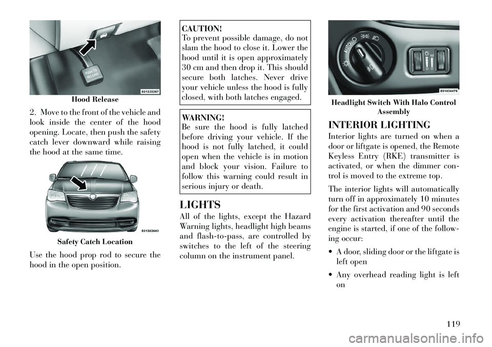
2. Move to the front of the vehicle and
look inside the center of the hood
opening. Locate, then push the safety
catch lever downward while raising
the hood at the same time.
Use the hood prop rod to secure the
hood in the open position.
CAUTION!
To prevent possible damage, do not
slam the hood to close it. Lower the
hood until it is open approximately
30 cm and then drop it. This should
secure both latches. Never drive
your vehicle unless the hood is fully
closed, with both latches engaged.WARNING!
Be sure the hood is fully latched
before driving your vehicle. If the
hood is not fully latched, it could
open when the vehicle is in motion
and block your vision. Failure to
follow this warning could result in
serious injury or death.
LIGHTS
All of the lights, except the Hazard
Warning lights, headlight high beams
and flash-to-pass, are controlled by
switches to the left of the steering
column on the instrument panel. INTERIOR LIGHTING
Interior lights are turned on when a
door or liftgate is opened, the Remote
Keyless Entry (RKE) transmitter is
activated, or when the dimmer con-
trol is moved to the extreme top.
The interior lights will automatically
turn off in approximately 10 minutes
for the first activation and 90 seconds
every activation thereafter until the
engine is started, if one of the follow-
ing occur:
A door, sliding door or the liftgate is
left open
Any overhead reading light is left on
Hood Release
Safety Catch Location
Headlight Switch With Halo Control Assembly
119