key Lancia Voyager 2012 Owner handbook (in English)
[x] Cancel search | Manufacturer: LANCIA, Model Year: 2012, Model line: Voyager, Model: Lancia Voyager 2012Pages: 344, PDF Size: 3.95 MB
Page 126 of 344

NOTE:
The key must be out of the ignition
switch or the ignition switch must
be in the OFF position for this fea-
ture to operate.
Dimmer Switch
The dimmer switch is located next to
the headlight switch.
Interior Lighting Off
Rotate the left dimmer control to the
off position (extreme bottom). The
interior lights will remain off when
the doors or liftgate are open.
Dimmer Control
With the parking lights or headlights
on, rotating the left dimmer control
for the interior lights on the instru-ment panel upward will increase the
brightness of the instrument panel
lights.
Parade Mode (Daytime Brightness
Feature)
Rotate the left dimmer control to the
first detent. This feature brightens the
odometer, radio and overhead dis-
plays when the parking lights or
headlights are on.
Interior Lights On
Rotate the left dimmer control com-
pletely upward to the second detent
(extreme top position) to turn on the
interior lights. The interior lights will
remain on when the dimmer control is
in this position.
Halo Lights (for versions/markets,
where provided)
Halo lights are strategically placed
soft lighting that help to illuminate
specific areas to aid the occupants in
locating specific features while driv-
ing at night.
The Halo control switch is located to
the right of the dimmer switch.
To activate the Halo lights,
rotate the Halo switch con-
trol upward or downward
to increase or decrease the
lighting.
PARKING LIGHTS
Turn the headlight switch knob
to the first detent to turn the
parking lights on. This also turns on
all instrument panel lighting.
HEADLIGHTS
Turn the headlight switch
knob to the second detent to
turn the headlights and
parking lights on. This also
turns on all instrument panel lighting.
Dimmer Switch
Halo Switch
120
Page 139 of 344

If “CLEAN PARK ASSIST SEN-
SORS” appears in the EVIC after
making sure the rear fascia/bumper is
free from snow, ice, mud, dirt or other
obstruction, see your authorized
dealer.
If “SERVICE PARK ASSIST SYS-
TEM” appears in the EVIC, see your
authorized dealer.
CLEANING THE
PARKSENSE® SYSTEM
Clean the ParkSense® sensors with
water, car wash soap and a soft cloth.
Do not use rough or hard cloths. Do
not scratch or poke the sensors. Oth-
erwise, you could damage the sensors.
PARKSENSE® SYSTEM
USAGE PRECAUTIONS
NOTE:
Ensure that the rear bumper isfree of snow, ice, mud, dirt and
debris to keep the ParkSense®
system operating properly.
Jackhammers, large trucks, and other vibrations could affect the
performance of ParkSense®. When you turn ParkSense® off,
the instrument cluster will dis-
play “PARK ASSIST SYSTEM
OFF.” Furthermore, once you
turn ParkSense® off, it remains
off until you turn it on again,
even if you cycle the ignition key.
When you move the shift lever to the REVERSE position and
ParkSense® is turned off, the
EVIC will display “PARK AS-
SIST SYSTEM OFF” message for
as long as the vehicle is in RE-
VERSE.
ParkSense®, when on, will re- duce the radio volume when it is
sounding a tone.
Clean the ParkSense® sensors regularly, taking care not to
scratch or damage them. The
sensors must not be covered
with ice, snow, slush, mud, dirt
or debris. Failure to do so can
result in the system not working
properly. The ParkSense® sys-
tem might not detect an obstacle
behind the fascia/bumper, or it could provide a false indication
that an obstacle is behind the
fascia/bumper.
Objects such as bicycle carriers, trailer hitches, etc., must not be
placed within 30 cm from the
rear fascia/bumper while driv-
ing the vehicle. Failure to do so
can result in the system misin-
terpreting a close object as a
sensor problem, causing the
“SERVICE PARK ASSIST SYS-
TEM” message to be displayed
in the EVIC.
On vehicles equipped with a tailgate, ParkSense® should be
disabled when the tailgate is in
the lowered or open position
and the vehicle is in REVERSE.
A lowered tailgate could provide
a false indication that an ob-
stacle is behind the vehicle.
133
Page 142 of 344

WARNING!
Drivers must be careful when back-
ing up even when using the
ParkView® Rear Back Up Camera.
Always check carefully behind your
vehicle, and be sure to check for
pedestrians, animals, other vehicles,
obstructions, or blind spots before
backing up. You are responsible for
the safety of your surroundings and
must continue to pay attention while
backing up. Failure to do so can
result in serious injury or death.CAUTION!
To avoid vehicle damage,ParkView® should only be used
as a parking aid. The camera is
unable to view every obstacle or
object in your drive path.
To avoid vehicle damage, the ve-
hicle must be driven slowly when
using ParkView® to be able to
stop in time when an obstacle is
seen. It is recommended that the
driver look frequently over his/
her shoulder when using
ParkView®. NOTE:
If snow, ice, mud, or any foreign
substance builds up on the camera
lens, clean the lens, rinse with wa-
ter, and dry with a soft cloth. Do
not cover the lens.
TURNING PARKVIEW® ON
OR OFF — WITH
NAVIGATION/
MULTIMEDIA RADIO
1. Press the “menu” hard-key.
2. Select “system setup” soft-key.
3. Press the “camera setup” soft-key.
4. Enable or disable the rear camera
feature by selecting “enable rear cam-
era in reverse” soft-key.
5. Press the “save” soft-key.
TURNING PARKVIEW® ON
OR OFF — WITHOUT
NAVIGATION/
MULTIMEDIA RADIO
1. Press the “menu” hard-key.
2. Select “system setup” soft-key.
3. Enable or disable the rear camera
feature by selecting “enable rear cam-
era in reverse” soft-key.
OVERHEAD CONSOLES
FRONT OVERHEAD
CONSOLE
Two versions of the overhead console
are available. The base front overhead
console model featured fixed incan-
descent courtesy/reading lights, flip-
down sunglass storage and conversa-
tion mirror. The premium front
overhead console model features a
LED focused light that illuminates
the instrument panel cupholders, two
swiveling LED lights, flip-down sun-
glass storage, conversation mirror,
optional power sliding door switches
and an optional power liftgate switch.
NOTE:
Premium sunroof console models
include all of above except sun-
glass storage.
136
Page 143 of 344

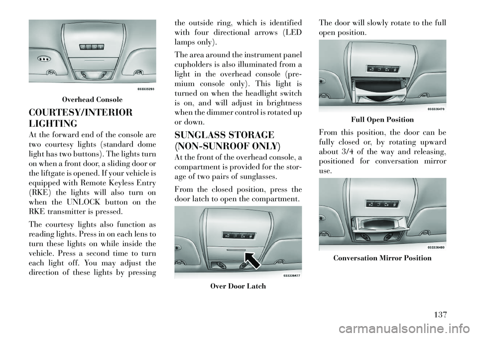
COURTESY/INTERIOR
LIGHTING
At the forward end of the console are
two courtesy lights (standard dome
light has two buttons). The lights turn
on when a front door, a sliding door or
the liftgate is opened. If your vehicle is
equipped with Remote Keyless Entry
(RKE) the lights will also turn on
when the UNLOCK button on the
RKE transmitter is pressed.
The courtesy lights also function as
reading lights. Press in on each lens to
turn these lights on while inside the
vehicle. Press a second time to turn
each light off. You may adjust the
direction of these lights by pressingthe outside ring, which is identified
with four directional arrows (LED
lamps only).
The area around the instrument panel
cupholders is also illuminated from a
light in the overhead console (pre-
mium console only). This light is
turned on when the headlight switch
is on, and will adjust in brightness
when the dimmer control is rotated up
or down.
SUNGLASS STORAGE
(NON-SUNROOF ONLY)
At the front of the overhead console, a
compartment is provided for the stor-
age of two pairs of sunglasses.
From the closed position, press the
door latch to open the compartment.
The door will slowly rotate to the full
open position.
From this position, the door can be
fully closed or, by rotating upward
about 3/4 of the way and releasing,
positioned for conversation mirror
use.
Overhead Console
Over Door Latch
Full Open Position
Conversation Mirror Position
137
Page 144 of 344

NOTE:
From the “conversation mirror”
position, the door can only be
closed.
To return to the full open position, the
door must first be closed and then
opened by pressing the latch again to
release.
REAR COURTESY/
READING LIGHTS (for
versions/markets, where
provided)
The overhead console has two sets of
courtesy lights. The lights turn on
when a front door, a sliding door or
the liftgate is opened. If your vehicle is
equipped with Remote Keyless Entry
(RKE) the lights will also turn on
when the UNLOCK button on the
RKE transmitter is pressed.
The courtesy lights also function as
reading lights. Press in on each lens to
turn these lights on while inside the
vehicle. Press the lens a second time to
turn each light off. You may adjust the
direction of these lights by pressing
the outside ring, which is identified
with four directional arrows.REAR OVERHEAD
CONSOLES (for
versions/markets, where
provided)
The rear overhead storage system is
available in two versions: with or
without sunroof.
An additional LED at the front of the
rear console shines down on the front
foot-well area while in courtesy mode,
for added convenience.
Rear Console Halo Lighting
The rear overhead console has re-
cessed halo lighting around the pe-
rimeter of the console base. This fea-
ture provides additional lighting
options while traveling and is con-
trolled by the headlight switch. Refer
to “Lights/Halo Lights (for versions/
markets, where provided)” in “Un-
derstanding The Features Of Your Ve-
hicle” for further information.
Reading Lights
Overhead Compartment Features1 — DVD
1
5 — Storage
2 — Rear HVAC 6 — DVD
1
3 — Interior
Lights 7 — Interior
Lights
4 — Storage 8 — Halo Light-
ing1(for versions/markets, where
equipped)
138
Page 145 of 344

POWER SUNROOF (for
versions/markets, where
provided)
The power sunroof switch is located
between the sun visors on the over-
head console.WARNING!
Never leave children in a vehiclewith the key in the ignition switch.
Occupants, particularly unat-
tended children, can become en-
trapped by the power sunroof
while operating the power sunroof
switch. Such entrapment may re-
sult in serious injury or death.
(Continued)
WARNING!(Continued)
In a collision, there is greater risk
of being thrown from a vehicle
with an open sunroof. You could
also be seriously injured or killed.
Always fasten your seat belt prop-
erly and make sure all passengers
are properly secured.
Do not allow small children to op-
erate the sunroof. Never allow
your fingers, other body parts, or
any object, to project through the
sunroof opening. Injury may re-
sult.
OPENING SUNROOF —
EXPRESS
Press the switch rearward and release
it within one-half second and the sun-
roof will open automatically from any
position. The sunroof will open fully
and stop automatically. This is called
“Express Open”. During Express
Open operation, any movement of the
sunroof switch will stop the sunroof. OPENING THE SUNROOF
— MANUAL MODE
To open the sunroof, press and hold
the switch rearward to full open. Any
release of the switch will stop the
movement and the sunroof will re-
main in a partially opened condition
until the switch is pushed and held
rearward again.
CLOSING SUNROOF —
EXPRESS
Press the switch forward and release it
within one-half second, and the sun-
roof will close automatically from any
position. The sunroof will close fully
and then stop automatically. This is
called “Express Close”. During Ex-
press Close operation, any movement
of the sunroof switch will stop the
sunroof.
CLOSING SUNROOF —
MANUAL MODE
To close the sunroof, press and hold
the switch in the forward position.
Any release of the switch will stop the
movement and the sunroof will re-
Power Sunroof Switch
139
Page 148 of 344

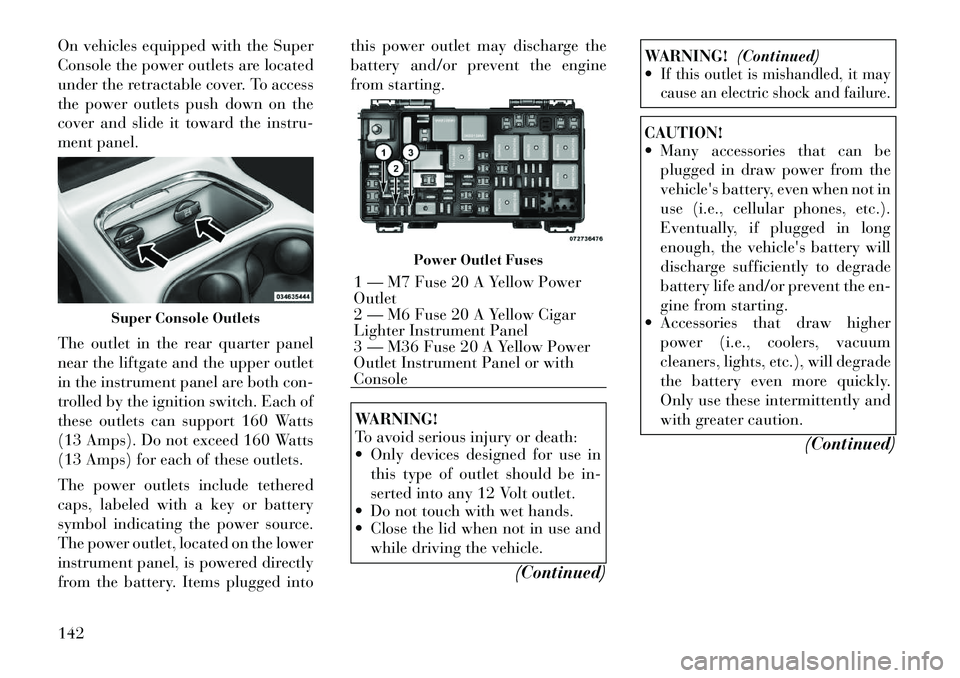
On vehicles equipped with the Super
Console the power outlets are located
under the retractable cover. To access
the power outlets push down on the
cover and slide it toward the instru-
ment panel.
The outlet in the rear quarter panel
near the liftgate and the upper outlet
in the instrument panel are both con-
trolled by the ignition switch. Each of
these outlets can support 160 Watts
(13 Amps). Do not exceed 160 Watts
(13 Amps) for each of these outlets.
The power outlets include tethered
caps, labeled with a key or battery
symbol indicating the power source.
The power outlet, located on the lower
instrument panel, is powered directly
from the battery. Items plugged intothis power outlet may discharge the
battery and/or prevent the engine
from starting.
WARNING!
To avoid serious injury or death:
Only devices designed for use in
this type of outlet should be in-
serted into any 12 Volt outlet.
Do not touch with wet hands.
Close the lid when not in use and
while driving the vehicle.
(Continued)
WARNING!(Continued)
If this outlet is mishandled, it may
cause an electric shock and failure.CAUTION!
Many accessories that can be
plugged in draw power from the
vehicle's battery, even when not in
use (i.e., cellular phones, etc.).
Eventually, if plugged in long
enough, the vehicle's battery will
discharge sufficiently to degrade
battery life and/or prevent the en-
gine from starting.
Accessories that draw higher
power (i.e., coolers, vacuum
cleaners, lights, etc.), will degrade
the battery even more quickly.
Only use these intermittently and
with greater caution.
(Continued)
Super Console Outlets
Power Outlet Fuses
1 — M7 Fuse 20 A Yellow Power
Outlet
2 — M6 Fuse 20 A Yellow Cigar
Lighter Instrument Panel
3 — M36 Fuse 20 A Yellow Power
Outlet Instrument Panel or with
Console
142
Page 158 of 344

CARGO AREA FEATURES
RECHARGEABLE
FLASHLIGHT (for
versions/markets, where
provided)
The rechargeable flashlight is
mounted on the right side of the cargo
area. The flashlight snaps out of the
bezel when needed. The flashlight
features two bright LED light bulbs
and is powered by a lithium battery
that recharges when snapped back
into place and the vehicle is either
running or the key is in the accessory
position.
Press in on the flashlight to release it.To operate the flashlight, press the
switch once for high, twice for low,
and a third time to return to off.
REAR WINDOW
FEATURES
REAR WINDOW
DEFROSTER
The rear window defroster
button is located on the climate
control (Mode) knob. Press
this button to turn on the rear window
defroster and the heated outside mir-
rors (for versions/markets, where
provided). An indicator in the button
will illuminate when the rear window
defroster is on. The rear window de-
froster automatically turns off after
approximately 10 minutes. For an ad- ditional five minutes of operation,
press the button a second time.
NOTE:
You can turn off the heated mir-
ror feature at anytime by press-
ing the rear window defroster
switch a second time.
To prevent excessive battery drain, use the rear window de-
froster only when the engine is
operating.
CAUTION!
Failure to follow these cautions can
cause damage to the heating ele-
ments:
Use care when washing the insideof the rear window. Do not use
abrasive window cleaners on the
interior surface of the window.
Use a soft cloth and a mild wash-
ing solution, wiping parallel to the
heating elements. Labels can be
peeled off after soaking with
warm water.
(Continued)
Press And Release
Three-Press Switch
152
Page 164 of 344

VEHICLE INFO (CUSTOMERINFORMATION FEATURES) . . . . . . . . . . . . . . 180
MESSAGES . . . . . . . . . . . . . . . . . . . . . . . . . . 180
UNITS . . . . . . . . . . . . . . . . . . . . . . . . . . . . . . 180
KEYLESS ENTER-N-GO DISPLAY (for versions/markets, where provided) . . . . . . . . 180
COMPASS / TEMPERATURE DISPLAY . . . . . 180
CUSTOMER-PROGRAMMABLE FEATURES (SYSTEM SETUP) . . . . . . . . . . . . . . . . . . . . . 183
SOUND SYSTEMS . . . . . . . . . . . . . . . . . . . . . . . 187
NAVIGATION SYSTEM (for versions/markets, where provided) . . . . . . . . . . . . . . . . . . . . . . . . . 187
iPod®/USB/MP3 CONTROL (for versions/ markets, where equipped) . . . . . . . . . . . . . . . . . 187
Connecting The iPod® Or External USB Device . . . . . . . . . . . . . . . . . . . . . . . . . . . . . . 188
Using This Feature . . . . . . . . . . . . . . . . . . . . . 188
Controlling The iPod® Or External USB Device Using Radio Buttons . . . . . . . . . . . . . . 188
Play Mode . . . . . . . . . . . . . . . . . . . . . . . . . . . 188
List Or Browse Mode . . . . . . . . . . . . . . . . . . . 189
Bluetooth Streaming Audio (BTSA) . . . . . . . . 191
UCONNECT™ MULTIMEDIA VIDEO ENTERTAINMENT SYSTEM (VES)™ (for
versions/markets, where provided) . . . . . . . . . . 191
Getting Started . . . . . . . . . . . . . . . . . . . . . . . . 191
Play Video Games . . . . . . . . . . . . . . . . . . . . . 192
158
Page 172 of 344

CAUTION!
The TPMS has been optimized for
the original equipment tires and
wheels. TPMS pressures and warn-
ing have been established for the tire
size equipped on your vehicle. Un-
desirable system operation or sensor
damage may result when using re-
placement equipment that is not of
the same size, type, and/or style.
Aftermarket wheels can cause sensor
damage. Do not use tire sealant from
a can or balance beads if your ve-
hicle is equipped with a TPMS, as
damage to the sensors may result.
9. Malfunction Indicator Light
(MIL) The Malfunction Indicator
Light (MIL) is part of an on-
board diagnostic system,
called OBD, that monitors en-
gine and automatic transmission con-
trol systems. The light will illuminate
when the key is in the ON/RUN posi-
tion, before engine start. If the bulb
does not come on when turning the
key from OFF to ON/RUN, have the
condition checked promptly. Certain conditions, such as a loose or
missing gas cap, poor fuel quality,
etc., may illuminate the MIL after en-
gine start. The vehicle should be ser-
viced if the light stays on through
several of your typical driving cycles.
In most situations, the vehicle will
drive normally and will not require
towing.
CAUTION!
Prolonged driving with the MIL on
could cause damage to the engine
control system. It also could affect
fuel economy and drivability. If the
MIL is flashing, severe catalytic con-
verter damage and power loss will
soon occur. Immediate service is re-
quired.
WARNING!
A malfunctioning catalytic con-
verter, as referenced above, can
reach higher temperatures than in
normal operating conditions. This
can cause a fire if you drive slowly or
park over flammable substances
such as dry plants, wood, cardboard,
etc. This could result in death or
serious injury to the driver, occu-
pants or others.
10. Electronic Stability Control
(ESC) Activation/Malfunction
Indicator Light (for versions/
markets, where provided) The “ESC Activation/
Malfunction Indicator
Light” in the instrument
cluster will come on when
the ignition switch is turned to the
ON/RUN position. It should go out
with the engine running. If the “ESC
Activation/Malfunction Indicator
Light” comes on continuously with
the engine running, a malfunction has
been detected in the ESC system. If
this light remains on after several ig-
nition cycles, and the vehicle has been
driven several kilometers at speeds
166