display Lancia Voyager 2012 Owner handbook (in English)
[x] Cancel search | Manufacturer: LANCIA, Model Year: 2012, Model line: Voyager, Model: Lancia Voyager 2012Pages: 344, PDF Size: 3.95 MB
Page 220 of 344
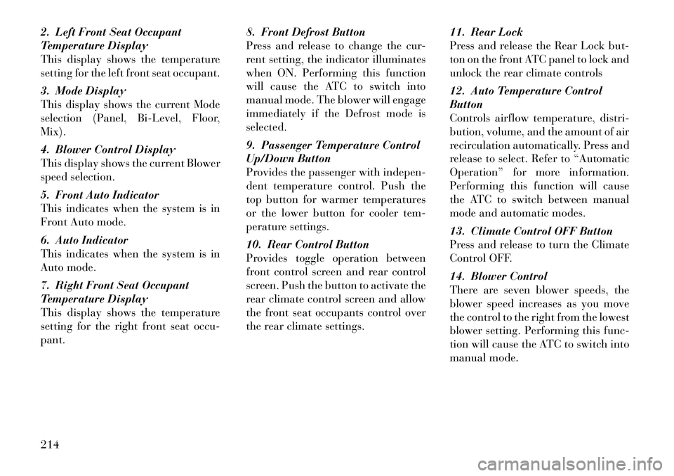
2. Left Front Seat Occupant
Temperature Display
This display shows the temperature
setting for the left front seat occupant.
3. Mode Display
This display shows the current Mode
selection (Panel, Bi-Level, Floor,
Mix).
4. Blower Control Display
This display shows the current Blower
speed selection.
5. Front Auto Indicator
This indicates when the system is in
Front Auto mode.
6. Auto Indicator
This indicates when the system is in
Auto mode.
7. Right Front Seat Occupant
Temperature Display
This display shows the temperature
setting for the right front seat occu-
pant.8. Front Defrost Button
Press and release to change the cur-
rent setting, the indicator illuminates
when ON. Performing this function
will cause the ATC to switch into
manual mode. The blower will engage
immediately if the Defrost mode is
selected.
9. Passenger Temperature Control
Up/Down Button
Provides the passenger with indepen-
dent temperature control. Push the
top button for warmer temperatures
or the lower button for cooler tem-
perature settings.
10. Rear Control Button
Provides toggle operation between
front control screen and rear control
screen. Push the button to activate the
rear climate control screen and allow
the front seat occupants control over
the rear climate settings.
11. Rear Lock
Press and release the Rear Lock but-
ton on the front ATC panel to lock and
unlock the rear climate controls
12. Auto Temperature Control
Button
Controls airflow temperature, distri-
bution, volume, and the amount of air
recirculation automatically. Press and
release to select. Refer to “Automatic
Operation” for more information.
Performing this function will cause
the ATC to switch between manual
mode and automatic modes.
13. Climate Control OFF Button
Press and release to turn the Climate
Control OFF.
14. Blower Control
There are seven blower speeds, the
blower speed increases as you move
the control to the right from the lowest
blower setting. Performing this func-
tion will cause the ATC to switch into
manual mode.
214
Page 221 of 344

15. Mode Control Button
Press and release to select between
Modes (Panel, Bi-Level, Floor, Mix).
Performing this function will cause
the ATC to switch into manual mode.
16. Recirculation Control Button
Press and release to change the cur-
rent setting, the indicator illuminates
when ON.
17. SYNC Button
Press and release to control the tem-
perature setting for all three zones
from the driver temperature control.
18. Driver Temperature Control
Up/Down Button
Provides the driver with independent
temperature control. Push the top
button for warmer temperatures or
the lower button for cooler tempera-
ture settings.
Controlling The Rear Climate
Controls From The Front ATC
Panel
The Three-Zone ATC system allows
for adjustment of the rear climate
controls from the front ATC panel.To change the rear system settings:
1. Press "REAR" button to change
control to rear control mode, Rear
display (below) will appear. Control
functions now operate rear system.
2. To return to Front screen, press
"REAR button again, or it will revert
to the Front screen after six seconds.
1. Mode Display
This display shows the current Mode
selection.
2. Rear Temperature Display
This display shows the temperature
setting for the rear seat occupants.
3. Blower Control Display
This display shows the current Blower
speed selection.
4. Rear Auto Indicator
This indicates when the system is in
Rear Auto mode.
Automatic Operation
1. Press the AUTO button on the
front ATC Panel and the words Front
Auto will illuminate in the front ATC
display, along with two temperatures
for the driver and front passenger.
The system will then automatically
regulate the amount of airflow.
2. Next, adjust the temperature you
would like the system to maintain, by
adjusting the driver, front passenger,
and rear seat rotary temperature
knobs. Once the desired temperature
is displayed, the system will achieve
and automatically maintain that com-
fort level.
Front ATC Panel Rear Control
Display
215
Page 222 of 344

3. When the system is set up for your
comfort level, it is not necessary to
change the settings. You will experi-
ence the greatest efficiency by simply
allowing the system to function auto-
matically.
NOTE:
It is not necessary to move thetemperature settings for cold or
hot vehicles. The system auto-
matically adjusts the tempera-
ture, mode and fan speed to pro-
vide comfort as quickly as
possible.
The temperature can be dis- played in English or Metric units
by selecting the “Display Units
of Measure in” customer-
programmable feature. Refer to
the “Electronic Vehicle Informa-
tion Center (EVIC) — Customer-
Programmable Features” in this
Section.
To provide you with maximum com-
fort in the automatic mode, during
cold start-ups, the blower fan will re-
main on low until the engine warms
up. The fan will engage immediately if the Defrost mode is selected, or by
changing the front blower knob set-
ting
Manual Operation
This system offers a full complement
of manual override features. The
AUTO symbol in the front ATC dis-
play will be turned off when the sys-
tem is being used in the manual mode.
NOTE:
Each of these features operate in-
dependently from each other. If
any one feature is controlled
manually, the temperature doors
will continue to operate automati-
cally.
There are seven
fixed blower
speeds. Use the
outer dial control
to regulate the
amount of air
forced through
the system in any mode you select.
The blower speed increases as you
move the control clockwise and
decreases when you move the con-
trol counter-clockwise. The blower fan speed can be set to any
fixed speed by adjusting the blower
control outer dial. The fan will now
operate at a fixed speed until addi-
tional speeds are selected. This allows
the front occupants to control the vol-
ume of air circulated in the vehicle
and cancel the Auto mode.
The operator can also select the direc-
tion of the airflow by selecting one of
the following positions.
Panel Mode
Air is directed through the outlets
in the instrument panel. These
outlets can be adjusted for direc-
tion, and turned on or off to control
airflow.
NOTE:
For maximum airflow to the rear,
the center instrument panel out-
lets can be directed toward the
rear seat passengers.216
Page 223 of 344

Bi-Level ModeAir comes from the instrument
panel outlets, floor outlets and
defrost outlets. A slight amount
of air is also directed through the side
window demister outlets.
NOTE:
In many temperature positions,
the Bi-Level mode is designed to
provide cooler air out of the panel
outlets and warmer air from the
floor outlets.
Floor Mode Air comes from the floor outlets.
A slight amount of air is directed
through the defrost and side
window demister outlets.
Mix Mode Air comes from the floor, defrost
and side window demist outlets.
This mode works best in cold or
snowy conditions. It allows you to stay
comfortable, while keeping the wind-
shield clear. Defrost Mode
Air comes from the windshield
and side window demist out-
lets. Use Defrost mode with
maximum blower and temperature
settings for best windshield and side
window defrosting.
NOTE:
While operating in the other
modes, the system will not auto-
matically sense the presence of fog,
mist or ice on the windshield. De-
frost mode must be manually se-
lected to clear the windshield and
side glass.
Air Conditioning (A/C)
The Air Conditioning (A/C) button
allows the operator to manually acti-
vate or deactivate the air conditioning
system. When in A/C mode and the
ATC is set to a cool temperature, de-
humidified air flows through the air
outlets. If Economy mode is desired,
press the A/C button to turn off the
A/C mode in the ATC display and
deactivate the A/C system. NOTE:
If the system is in Mix, Floor or
Defrost Mode, the A/C can be
turned off, but the A/C system
shall remain active to prevent
fogging of the windows.
If fog or mist appears on the windshield or side glass, select
Defrost mode and increase
blower speed.
Recirculation Control When outside air contains
smoke, odors, or high hu-
midity, or if rapid cooling is
desired, you may wish to
recirculate interior air by pressing the
Recirculation control button. Recir-
culation mode should only be used
temporarily. A LED will illuminate on
the Recirculation control button when
Recirculation mode is selected. Push
the button a second time to turn off
the Recirculation mode LED and al-
low outside air into the vehicle.
217
Page 225 of 344

NOTE:
It is not necessary to move thetemperature settings for cold or
hot vehicles. The system auto-
matically adjusts the tempera-
ture, mode and fan speed to pro-
vide comfort as quickly as
possible.
The temperature can be dis- played in English or Metric units
by selecting the “Display Units
of Measure in” customer-
programmable feature. Refer to
the “Electronic Vehicle Informa-
tion Center (EVIC) — Customer-
Programmable Features” in this
Section.
Rear Blower Control
The rear blower control knob can be
manually set to off, or any fixed
blower speed, by rotating the knob
from low to high. This allows the rear
seat occupants to control the volume
of air circulated in the rear of the
vehicle.
CAUTION!
Interior air enters the Rear Auto-
matic Temperature Control System
through an intake grille, located in
the right side trim panel behind the
third row seats. The heater outlets
are located in the right side trim
panel, just behind the sliding door.
Do not block or place objects di-
rectly in front of the inlet grille or
heater outlets. The electrical system
could overload causing damage to
the blower motor.
Rear Temperature Control
To change the temperature in the rear
of the vehicle, rotate the temperature
knob counterclockwise to lower the
temperature, and clockwise to in-
crease the temperature. The rear tem-
perature settings are displayed in the
front ATC panel.
When rear controls are locked by the
front system, the Rear Temperature
Lock symbol on the temperature
knob is illuminated and any rear over-
head adjustments are ignored. Rear Mode Control
Auto Mode
The rear system automatically main-
tains the correct mode and comfort
level desired by the rear seat occu-
pants.
Headliner Mode
Air comes from the outlets in the
headliner. Each of these outlets
can be individually adjusted to
direct the flow of air. Moving the air
vanes of the outlets to one side will
shut off the airflow.
Bi-Level Mode
Air comes from both the head-
liner outlets and the floor out-
lets.
NOTE:
In many temperature positions,
the Bi-Level mode is designed to
provide cooler air out of the head-
liner outlets and warmer air from
the floor outlets.
219
Page 232 of 344
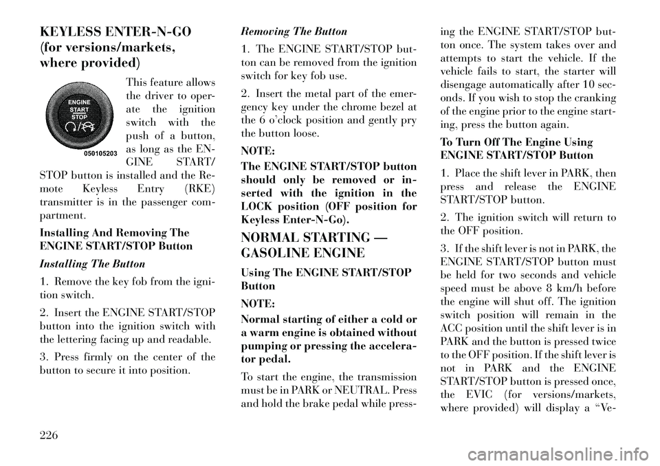
KEYLESS ENTER-N-GO
(for versions/markets,
where provided)This feature allows
the driver to oper-
ate the ignition
switch with the
push of a button,
as long as the EN-
GINE START/
STOP button is installed and the Re-
mote Keyless Entry (RKE)
transmitter is in the passenger com-
partment.
Installing And Removing The
ENGINE START/STOP Button
Installing The Button
1. Remove the key fob from the igni-
tion switch.
2. Insert the ENGINE START/STOP
button into the ignition switch with
the lettering facing up and readable.
3. Press firmly on the center of the
button to secure it into position. Removing The Button
1. The ENGINE START/STOP but-
ton can be removed from the ignition
switch for key fob use.
2. Insert the metal part of the emer-
gency key under the chrome bezel at
the 6 o’clock position and gently pry
the button loose.
NOTE:
The ENGINE START/STOP button
should only be removed or in-
serted with the ignition in the
LOCK position (OFF position for
Keyless Enter-N-Go).
NORMAL STARTING —
GASOLINE ENGINE
Using The ENGINE START/STOP
Button
NOTE:
Normal starting of either a cold or
a warm engine is obtained without
pumping or pressing the accelera-
tor pedal.
To start the engine, the transmission
must be in PARK or NEUTRAL. Press
and hold the brake pedal while press-ing the ENGINE START/STOP but-
ton once. The system takes over and
attempts to start the vehicle. If the
vehicle fails to start, the starter will
disengage automatically after 10 sec-
onds. If you wish to stop the cranking
of the engine prior to the engine start-
ing, press the button again.
To Turn Off The Engine Using
ENGINE START/STOP Button
1. Place the shift lever in PARK, then
press and release the ENGINE
START/STOP button.
2. The ignition switch will return to
the OFF position.
3. If the shift lever is not in PARK, the
ENGINE START/STOP button must
be held for two seconds and vehicle
speed must be above 8 km/h before
the engine will shut off. The ignition
switch position will remain in the
ACC position until the shift lever is in
PARK and the button is pressed twice
to the OFF position. If the shift lever is
not in PARK and the ENGINE
START/STOP button is pressed once,
the EVIC (for versions/markets,
where provided) will display a “Ve-226
Page 233 of 344
hicle Not In Park” message and the
engine will remain running. Never
leave a vehicle out of the PARK posi-
tion, or it could roll.
NOTE:
If the ignition switch is left in the
ACC or RUN (engine not running)
position and the transmission is in
PARK, the system will automati-
cally time out after 30 minutes of
inactivity and the ignition will
switch to the OFF position.
Keyless Enter-N-Go Functions –
With Driver’s Foot OFF The
Brake Pedal (In PARK Or
NEUTRAL Position)
The Keyless Enter-N-Go feature oper-
ates similar to an ignition switch. It
has four positions, OFF, ACC, RUN
and START. To change the ignition
switch positions without starting the
vehicle and use the accessories follow
these steps. Starting with the ignition switch in
the OFF position:
Press the ENGINE START/STOP button once to change the ignition
switch to the ACC position (EVIC
displays “IGNITION MODE AC-
CESSORY”),
Press the ENGINE START/STOP button a second time to change the
ignition switch to the RUN position
(EVIC displays “IGNITION MODE
RUN”),
Press the ENGINE START/STOP button a third time to return the
ignition switch to the OFF position
(EVIC displays “IGNITION MODE
OFF”).
EXTREME COLD
WEATHER (BELOW �29°C)
To ensure reliable starting at these
temperatures, use of an externally
powered electric engine block heater
is recommended. IF ENGINE FAILS TO
START
WARNING!
Never pour fuel or other flam-
mable liquids into the throttle
body air inlet opening in an at-
tempt to start the vehicle. This
could result in a flash fire causing
serious personal injury.
Do not attempt to push or tow
your vehicle to get it started. Ve-
hicles equipped with an automatic
transmission cannot be started
this way. Unburned fuel could en-
ter the catalytic converter and
once the engine has started, ignite
and damage the converter and ve-
hicle. If the vehicle has a dis-
charged battery, booster cables
may be used to obtain a start from
a booster battery or the battery in
another vehicle. This type of start
can be dangerous if done improp-
erly. Refer to “Jump Starting” in
“What To Do In Emergencies” for
further information.
227
Page 237 of 344
LOCK/OFF position, and once re-
moved, the shift lever is locked in
PARK.
This system prevents the key fob from
being removed unless the shift lever is
in PARK.
NOTE:
If a malfunction occurs, the system
will trap the key fob in the ignition
cylinder to warn you that this
safety feature is inoperable. The
engine can be started and stopped
but the key fob cannot be removed
until you obtain service.
BRAKE/TRANSMISSION
SHIFT INTERLOCK
SYSTEM
This vehicle is equipped with a Brake
Transmission Shift Interlock System
(BTSI) that holds the shift lever in the
PARK position unless the brakes are
applied. To move the shift lever out of
the PARK position, the ignition switch
must be turned to the ON/RUN posi-
tion (engine running or not) and the
brake pedal must be pressed.SIX-SPEED AUTOMATIC
TRANSMISSION
The shift lever position display (lo-
cated in the instrument panel cluster)
indicates the transmission gear range.
You must press the brake pedal to
move the shift lever out of the PARK
position (Refer to Brake/
Transmission Shift Interlock System
in this section). To drive, move the
shift lever from PARK or NEUTRAL
to the DRIVE position.
The electronically-controlled trans-
mission provides a precise shift sched-
ule. The transmission electronics are
self-calibrating; therefore, the first
few shifts on a new vehicle may be
somewhat abrupt. This is a normal
condition, and precision shifts will de-
velop within a few hundred kilome-
ters.
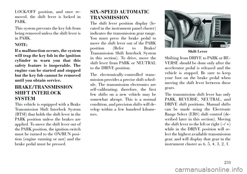
Shifting from DRIVE to PARK or RE-
VERSE should be done only after the
accelerator pedal is released and the
vehicle is stopped. Be sure to keep
your foot on the brake pedal when
moving the shift lever between these
gears.
The transmission shift lever has only
PARK, REVERSE, NEUTRAL, and
DRIVE shift positions. Manual shifts
can be made using the Electronic
Range Select (ERS) shift control (de-
scribed later in this section). Moving
the shift lever to the left or right (–/ +)
while in the DRIVE position will se-
lect the highest available transmission
gear, and will display that gear in the
instrument cluster as 6, 5, 4, 3, 2, 1.
Shift Lever
231
Page 241 of 344

but will shift down into second and
first gear normally.
You can switch between DRIVE and
ERS mode at any vehicle speed. When
the shift lever is in the DRIVE posi-
tion, the transmission will operate au-
tomatically, shifting between all
available gears. Tapping the shift le-
ver to the left (-) will activate ERS
mode, display the current gear in theinstrument cluster, and maintain that
gear as the top available gear. Once in
ERS mode, tapping the shift lever to
the left (-) or right (+) will change the
top available gear.
To exit ERS mode, simply press and
hold the shift lever to the right (+)
until “D” is once again displayed in
the shift lever position indicator in the
instrument cluster.
WARNING!
Do not downshift for additional en-
gine braking on a slippery surface.
The drive wheels could lose their
grip and the vehicle could skid,
causing an accident or personal in-
jury.
Odometer Screen Display
1 2 3 4 5 6 D
Actual Gear(s) Allowed 1 1-2 1-3 1-4 1-5 1-6 1-6
NOTE:
To select the proper gear position
for maximum deceleration (engine
braking), tap the shift lever to the
left (-) repeatedly as the vehicle
slows. The transmission will shift
to the range from which the vehicle
can best be slowed down. Overdrive Operation
The automatic transmission includes
an electronically controlled Overdrive
(sixth gear). The transmission will
automatically shift into the Overdrive
gear if the following conditions are
present:
the shift lever is in the DRIVE po-
sition,
the transmission fluid has reached an adequate temperature,
the engine coolant has reached an adequate temperature,
vehicle speed is sufficiently high, and the driver is not heavily pressing
the accelerator
Torque Converter Clutch
A feature designed to improve fuel
economy has been included in the au-
tomatic transmission on your vehicle.
A clutch within the torque converter
engages automatically at calibrated
speeds. This may result in a slightly
different feeling or response during
normal operation in the upper gears.
When the vehicle speed drops or dur-
ing some accelerations, the clutch au-
tomatically disengages.
235
Page 258 of 344
The TPMS should not be used asa tire pressure gauge while ad-
justing your tire pressure.
Driving on a significantly under- inflated tire causes the tire to
overheat and can lead to tire
failure. Under-inflation also re-
duces fuel efficiency and tire
tread life, and may affect the ve-
hicle’s handling and stopping
ability.
The TPMS is not a substitute for proper tire maintenance, and it
is the driver's responsibility to
maintain correct tire pressure,
using an accurate tire pressure
gage, even if under-inflation has
not reached the level to trigger
illumination of the “Tire Pres-
sure Monitoring Telltale Light.”
Seasonal temperature changes will affect tire pressure, and the
TPMS will monitor the actual
tire pressure in the tire.
BASE SYSTEM
The TPMS uses wireless technology
with wheel rim mounted electronic
sensors to monitor tire pressure levels. Sensors, mounted to each wheel as
part of the valve stem, transmit tire
pressure readings to the Receiver
Module.
NOTE:
It is particularly important for you
to check the tire pressure in all of
your tires regularly and to main-
tain the proper pressure.
The Basic TPMS consists of the fol-
lowing components:
Receiver Module
Four Tire Pressure Monitoring Sen-
sors
TPMS Telltale Warning Light
Tire Pressure Monitoring Low
Tire Pressure Warnings The “Tire Pressure Moni-
toring Telltale Light” will
illuminate in the instru-
ment cluster, a "TIRE LOW
PRESSURE" message will display in
the instrument cluster, and an audible
chime will be activated when one or
more of the four active road tire pres-
sures are low. Should this occur, you
should stop as soon as possible, check the inflation pressure of each tire on
your vehicle, and inflate each tire to
the vehicle's recommended cold tire
pressure value (located on the placard
on the driver's-side B-Pillar). The
system will automatically update and
the “Tire Pressure Monitoring Telltale
Light” will extinguish once the up-
dated tire pressures have been re-
ceived.
NOTE:
The vehicle may need to be driven
for up to 20 minutes above 24 km/h
to receive this information.
The “Tire Pressure Monitoring Tell-
tale Light” will flash on and off for
75 seconds, and remain on solid when
a system fault is detected. The system
fault will also sound a chime. If the
ignition switch is cycled, this se-
quence will repeat, providing the sys-
tem fault still exists. The “Tire Pres-
sure Monitoring Telltale Light” will
turn off when the fault condition no
longer exists. A system fault can occur
with any of the following scenarios:252