child lock Lancia Voyager 2012 Owner handbook (in English)
[x] Cancel search | Manufacturer: LANCIA, Model Year: 2012, Model line: Voyager, Model: Lancia Voyager 2012Pages: 344, PDF Size: 3.95 MB
Page 16 of 344
PROGRAMMING ADDITIONALTRANSMITTERS . . . . . . . . . . . . . . . . . . . . . . . 21
TRANSMITTER BATTERY REPLACEMENT . . . 21
GENERAL INFORMATION . . . . . . . . . . . . . . . . 22
DOOR LOCKS . . . . . . . . . . . . . . . . . . . . . . . . . . . 22 MANUAL DOOR LOCKS . . . . . . . . . . . . . . . . . 22
POWER DOOR LOCKS (for versions/markets, where provided) . . . . . . . . . . . . . . . . 23
KEYLESS ENTER-N-GO . . . . . . . . . . . . . . . . . . . 24
WINDOWS . . . . . . . . . . . . . . . . . . . . . . . . . . . . . . 26 POWER VENT WINDOWS (forversions/markets, where provided) . . . . . . . . . 26
POWER WINDOWS . . . . . . . . . . . . . . . . . . . . . 26
WIND BUFFETING . . . . . . . . . . . . . . . . . . . . . 28
SLIDING SIDE DOOR . . . . . . . . . . . . . . . . . . . . . 28 POWER SLIDING SIDE DOOR (forversions/markets, where provided) . . . . . . . . . 29
SLIDING SIDE DOOR CHILD PROTECTION LOCK . . . . . . . . . . . . . . . . . . . . . . . . . . . . . . . . 31
LIFTGATE . . . . . . . . . . . . . . . . . . . . . . . . . . . . . . 32 POWER LIFTGATE (for versions/markets,where available) . . . . . . . . . . . . . . . . . . . . . . . 32
OCCUPANT RESTRAINTS . . . . . . . . . . . . . . . . . . 34 LAP/SHOULDER BELTS . . . . . . . . . . . . . . . . . 35
SEAT BELTS IN PASSENGER SEATINGPOSITIONS . . . . . . . . . . . . . . . . . . . . . . . . . . . 38
10
Page 17 of 344

AUTOMATIC LOCKING RETRACTOR MODE(ALR) . . . . . . . . . . . . . . . . . . . . . . . . . . . . . . . . 38
ENERGY MANAGEMENT FEATURE . . . . . . . . 39
SEAT BELT PRETENSIONERS . . . . . . . . . . . . . 39
SUPPLEMENTAL ACTIVE HEAD RESTRAINTS (AHR) . . . . . . . . . . . . . . . . . . . . 40
ACTIVE HOOD SYSTEM . . . . . . . . . . . . . . . . . 41
ENHANCED SEAT BELT USE REMINDER SYSTEM (BeltAlert®) . . . . . . . . . . . . . . . . . . . . 43
SEAT BELTS AND PREGNANT WOMEN . . . . . 44
SUPPLEMENTAL RESTRAINT SYSTEM (SRS) — AIR BAGS . . . . . . . . . . . . . . . . . . . . . 44
AIR BAG SYSTEM COMPONENTS . . . . . . . . . . 45
ADVANCED FRONT AIR BAG FEATURES . . . . 45
AIR BAG DEPLOYMENT SENSORS AND CONTROLS . . . . . . . . . . . . . . . . . . . . . . . . . . . 48
EVENT DATA RECORDER (EDR) . . . . . . . . . . . 52
CHILD RESTRAINTS . . . . . . . . . . . . . . . . . . . . 53
ENGINE BREAK-IN RECOMMENDATIONS . . . . . 62 Additional Requirements For Diesel Engine(for versions/markets, where provided) . . . . . . 63
SAFETY TIPS . . . . . . . . . . . . . . . . . . . . . . . . . . . 63
11
Page 20 of 344
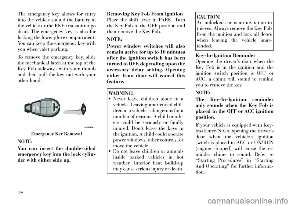
The emergency key allows for entry
into the vehicle should the battery in
the vehicle or the RKE transmitter go
dead. The emergency key is also for
locking the lower glove compartment.
You can keep the emergency key with
you when valet parking.
To remove the emergency key, slide
the mechanical latch at the top of the
Key Fob sideways with your thumb
and then pull the key out with your
other hand.
NOTE:
You can insert the double-sided
emergency key into the lock cylin-
der with either side up.Removing Key Fob From Ignition
Place the shift lever in PARK. Turn
the Key Fob to the OFF position and
then remove the Key Fob.
NOTE:
Power window switches will also
remain active for up to 10 minutes
after the ignition switch has been
turned to OFF, depending upon the
accessory delay setting. Opening
either front door will cancel this
feature.
WARNING!
Never leave children alone in a
vehicle. Leaving unattended chil-
dren in a vehicle is dangerous for a
number of reasons. A child or oth-
ers could be seriously or fatally
injured. Don't leave the keys in
the ignition. A child could operate
power windows, other controls, or
move the vehicle.
Do not leave children or animals
inside parked vehicles in hot
weather. Interior heat build-up
may cause serious injury or death.
CAUTION!
An unlocked car is an invitation to
thieves. Always remove the Key Fob
from the ignition and lock all doors
when leaving the vehicle unat-
tended.
Key-In-Ignition Reminder
Opening the driver's door when the
Key Fob is in the ignition and the
ignition switch position is OFF or
ACC, a chime will sound to remind
you to remove the key.
NOTE:
The Key-In-Ignition reminder
only sounds when the Key Fob is
placed in the OFF or ACC ignition
position.
If your vehicle is equipped with Key-
less Enter-N-Go, opening the driver’s
door when the vehicle’s ignition
switch is placed in ACC or ON/RUN
(engine stopped) will cause the re-
minder chime to sound. Refer to
“Starting Procedures” in “Starting
And Operating” for further informa-
tion.
Emergency Key Removal
14
Page 28 of 344
GENERAL INFORMATION
The RKE transmitter(s) and receivers
operate on a carrier frequency of
433.92 MHz. Operation is subject to
the following conditions:
This device may not cause harmfulinterference.
This device must accept any inter- ference received, including interfer-
ence that may cause undesired op-
eration.
If your RKE transmitter fails to oper-
ate from a normal distance, check for
these two conditions.
1. A weak battery in the RKE trans-
mitter. The expected life of the battery
is a minimum of three years.
2. Closeness to a radio transmitter
such as a radio station tower, airport
transmitter, and some mobile or CB
radios.
DOOR LOCKS
MANUAL DOOR LOCKS
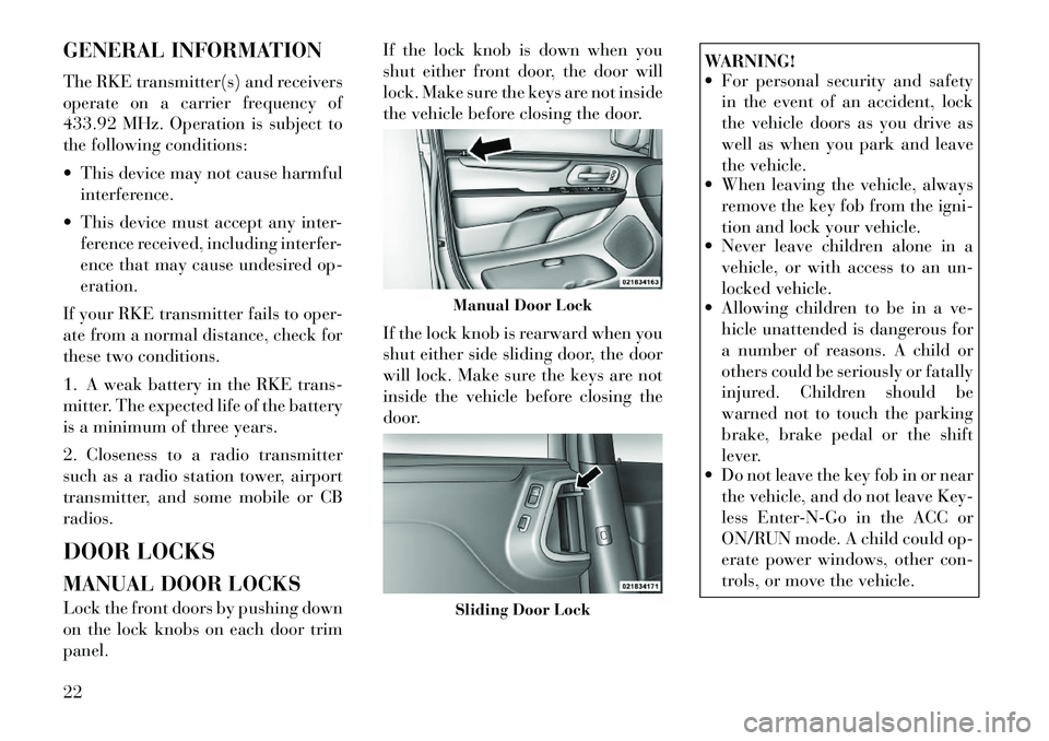
Lock the front doors by pushing down
on the lock knobs on each door trim
panel. If the lock knob is down when you
shut either front door, the door will
lock. Make sure the keys are not inside
the vehicle before closing the door.
If the lock knob is rearward when you
shut either side sliding door, the door
will lock. Make sure the keys are not
inside the vehicle before closing the
door.
WARNING!
For personal security and safety
in the event of an accident, lock
the vehicle doors as you drive as
well as when you park and leave
the vehicle.
When leaving the vehicle, always
remove the key fob from the igni-
tion and lock your vehicle.
Never leave children alone in a
vehicle, or with access to an un-
locked vehicle.
Allowing children to be in a ve-
hicle unattended is dangerous for
a number of reasons. A child or
others could be seriously or fatally
injured. Children should be
warned not to touch the parking
brake, brake pedal or the shift
lever.
Do not leave the key fob in or near
the vehicle, and do not leave Key-
less Enter-N-Go in the ACC or
ON/RUN mode. A child could op-
erate power windows, other con-
trols, or move the vehicle.
Manual Door LockSliding Door Lock
22
Page 36 of 344
until it is fully open and then
press the switch again.
If the power sliding door en- counters multiple obstructions
within the same cycle, the sys-
tem will automatically stop, the
power sliding door motor will
make a clicking sound until the
door has no further movement.
This clicking sound can be
stopped by pulling the inside or
outside handle. If this condition
occurs, no damage is done to the
power sliding door motor. The
power sliding door must be
opened or closed manually.WARNING!
You, or others, could be injured if
caught in the path of the sliding
door. Make sure the door path is
clear before closing the door.
Power Sliding Side Door Open
Flash
The left and right exterior hazard
lights will flash for 12 seconds when
either sliding door is opened. This will alert other drivers in the area that
passenger(s) could be entering or ex-
iting the vehicle.
The Sliding Side Door Open Flash can
be enabled or disabled by performing
the following procedure:
1. Place the Key Fob in the ignition
switch.
2. Cycle the ignition switch from ON/
RUN to OFF five times ending in the
ON/RUN position
(do not start the
engine).
3. Within 10 seconds of the final
cycle, press the HAZARD switch ON.
4. A single chime will sound to signify
that you have successfully completed
the programming.
You can turn the feature back on by
repeating the previous procedure.
Power Sliding Side Door Master
Lock Switch
To provide a safer environment for
small children riding in the rear seats,
the second row sliding door switches
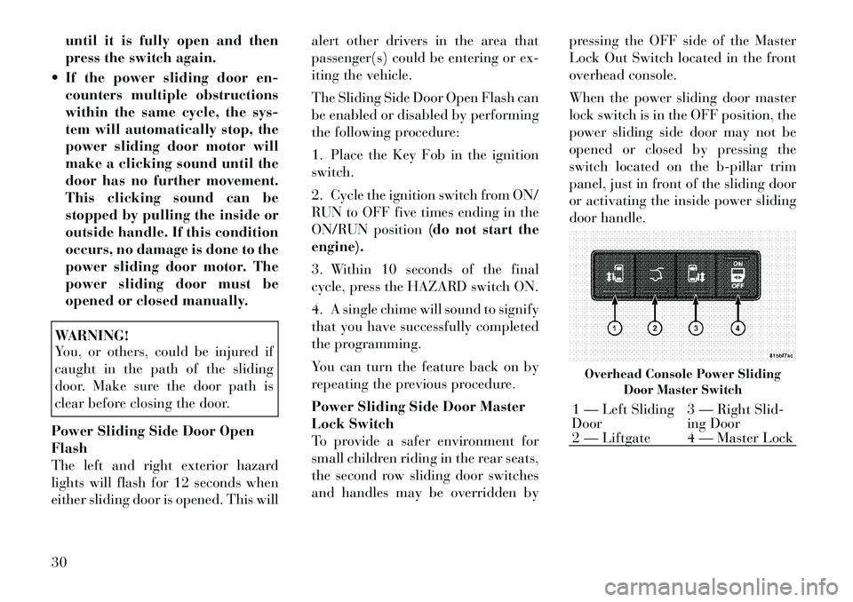
and handles may be overridden by pressing the OFF side of the Master
Lock Out Switch located in the front
overhead console.
When the power sliding door master
lock switch is in the OFF position, the
power sliding side door may not be
opened or closed by pressing the
switch located on the b-pillar trim
panel, just in front of the sliding door
or activating the inside power sliding
door handle.
Overhead Console Power Sliding
Door Master Switch1 — Left Sliding
Door 3 — Right Slid-
ing Door
2 — Liftgate 4 — Master Lock
30
Page 37 of 344

SLIDING SIDE DOOR
CHILD PROTECTION
LOCK
To provide a safer environment for
small children riding in the rear seats,
the sliding doors are equipped with a
Child Protection Door Lock system.
NOTE:
When the Child Protection Door
Lock system is engaged, the door
can be opened only by using the
outside door handle even though
the inside door lock is in the un-
locked position.
To Engage the Child Protection
Door Lock
1. Open the sliding side door.
2. Slide the Child Protection Door
Lock control inward (toward the ve-
hicle) to engage the Child Protection
Door Lock.3. Repeat Steps 1 and 2 on the oppo-
site sliding door.
NOTE:
After engaging the Child Protec-
tion Door Lock, always test the
door from the inside to make
certain it is in the desired posi-
tion.
When the Child Protection Door Lock system is engaged, (even if
the inside door lock is in the
unlocked position) the door can
be opened only by using the out-
side door handle, the RKE
transmitter, the switches on the
overhead console or the switches
located on the trim panel just in
front of the power sliding door. The power sliding side door will
operate from the switches lo-
cated on the trim panel just in
front of the power sliding door,
regardless of the Child Protec-
tion Door Lock lever position. To
avoid unintentional operation of
the power sliding door from the
rear seats, press the "OFF” Mas-
ter Lock Out Switch located in
the front overhead console, next
to the driver.
WARNING!
Avoid trapping anyone in the vehicle
in a collision. Remember that the
sliding doors can only be opened
from the outside door handle or the
switches located on the trim panel
just in front of the power sliding
door when the Child Protection Door
Locks are engaged.
To Disengage the Child Protection
Door Lock
1. Open the sliding side door.
Child Protection Door Lock
31
Page 38 of 344
2. Slide the Child Protection Door
Lock control outward (away from the
vehicle) to disengage the Child Pro-
tection Door Lock.
3. Repeat Steps 1 and 2 on the oppo-
site sliding door (for versions/
markets, where provided).
NOTE:
After setting the Child Protec-tion Door Lock system, always
test the door from the inside to
make certain it is in the desired
position.
The power sliding side door switches will not open the power
sliding doors if the vehicle is in
gear or the vehicle speed is
above 0 km/h.
The power sliding door will op- erate from the outside door
handle, the RKE transmitter, the
switches on the overhead con-
sole, or the switches located on
the trim panel just in front of the
power sliding door when the
shift lever is in PARK, regardless
of the child lock lever position. LIFTGATE
On vehicles equipped with power
locks, the liftgate can be unlocked
using the Remote Keyless Entry
(RKE) transmitter button, or by acti-
vating the power door lock switches
located on the front doors.
To open the liftgate, press the liftgate
release handle located on the under-
side of the license plate bar and pull
the liftgate open with one fluid mo-
tion.
POWER LIFTGATE (for
versions/markets, where
available)
The power liftgate may be opened
manually or by using the button on
the Remote Keyless Entry (RKE)
transmitter. Press the button on the transmitter twice within five seconds,
to open the power liftgate. When the
liftgate is fully open, pressing the but-
ton twice within five seconds, a sec-
ond time, will close the liftgate.
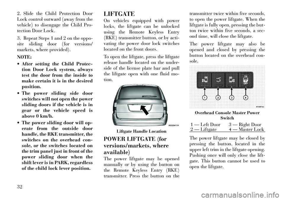
The power liftgate may also be
opened and closed by pressing the
button located on the overhead con-
sole.
The power liftgate may be closed by
pressing the button, located in the
upper left trim in the liftgate opening.
Pushing once will only close the lift-
gate. This button cannot be used to
open the liftgate.
Liftgate Handle Location
Overhead Console Master Power
Switch1 — Left Door 3 — Right Door
2 — Liftgate 4 — Master Lock
32
Page 40 of 344

Gas props support the liftgate in the
open position. However, because the
gas pressure drops with temperature,
it may be necessary to assist the props
when opening the liftgate in cold
weather.
OCCUPANT RESTRAINTS
Some of the most important safety
features in your vehicle are the re-
straint systems:
Three-point lap and shoulder beltsfor all seating positions
Advanced Front Air Bags for driver and front passenger
Supplemental Active Head Re- straints (AHR) located on top of the
front seats (integrated into the head
restraint)
Supplemental Side Air Bag Inflat- able Curtains (SABIC) that span
the front, second, and third row
seating for the driver and passen-
gers seated next to a window
Supplemental Seat-Mounted Side Air Bags (SAB)
An energy-absorbing steering col- umn and steering wheel Knee bolsters/blockers for front
seat occupants (for versions/
markets, where provided)
Front seat belts incorporate preten- sioners that may enhance occupant
protection by managing occupant
energy during an impact event
All seat belt systems (except the driver’s) include Automatic Lock-
ing Retractors (ALRs), which lock
the seat belt webbing into position
by extending the belt all the way
out and then adjusting the belt to
the desired length to restrain a child
seat or secure a large item in a seat
If you will be carrying children too
small for adult-sized seat belts, the
seat belts or the ISOFIX feature also
can be used to hold infant and child
restraint systems. For more informa-
tion on ISOFIX, see ISOFIX — Child
Seat Anchorage System.
NOTE:
The Advanced Front Air Bags have
a multistage inflator design. This
allows the air bag to have different
rates of inflation based on several
factors, including the severity and
type of collision. Please pay close attention to the infor-
mation in this section. It tells you how
to use your restraint system properly,
to keep you and your passengers as
safe as possible.
WARNING!
In a collision, you and your passen-
gers can suffer much greater injuries
if you are not properly buckled up.
You can strike the interior of your
vehicle or other passengers, or you
can be thrown out of the vehicle.
Always be sure you and others in
your vehicle are buckled up prop-
erly.
Buckle up even though you are an
excellent driver, even on short trips.
Someone on the road may be a poor
driver and cause a collision that in-
cludes you. This can happen far away
from home or on your own street.
Research has shown that seat belts
save lives, and they can reduce the
seriousness of injuries in a collision.
Some of the worst injuries happen
when people are thrown from the ve-
hicle. Seat belts reduce the possibility
of ejection and the risk of injury
34
Page 44 of 344

3. Slide the latch plate upward over
the folded webbing. The folded web-
bing must enter the slot at the top of
the latch plate.
4. Continue to slide the latch plate up
until it clears the folded webbing.
Adjustable Upper Shoulder Belt
Anchorage
In the front seats and the second row
outboard seats, the shoulder belt an-
chorage can be adjusted upward or
downward to help position the belt
away from your neck. The upper an-
chorage can be adjusted upward by
pushing anywhere on the anchorage.
To move the anchorage downward,
squeeze the actuation buttons while
simultaneously pushing down on the
anchorage assembly.
As a guide, if you are shorter than
average you will prefer a lower posi-
tion, and if you are taller than average
you will prefer a higher position.
When you release the anchorage, try
to move it up or down to make sure
that it is locked in position.SEAT BELTS IN
PASSENGER SEATING
POSITIONS
The seat belts in the passenger seating
positions are equipped with Auto-
matic Locking Retractors (ALR)
which are used to secure a child re-
straint system. For additional infor-
mation, refer to “Installing Child Re-
straints Using The Vehicle Seat Belt”
under the “Child Restraints” section.
The chart below defines the type of
feature for each seating position.
Driver Center Passen-
ger
First
Row N/A N/A ALR
Second Row ALR N/A ALR
Third Row ALR Cinch ALR
N/A — Not Applicable
ALR — Automatic Locking Retrac- tor
If the passenger seating position is
equipped with an ALR and is being
used for normal usage: Only pull the belt webbing out far
enough to comfortably wrap around
the occupant's mid-section so as to
not activate the ALR. If the ALR is
activated, you will hear a ratcheting
sound as the belt retracts. Allow the
webbing to retract completely in this
case and then carefully pull out only
the amount of webbing necessary to
comfortably wrap around the occu-
pant's mid-section. Slide the latch
plate into the buckle until you hear a
"click."
AUTOMATIC LOCKING
RETRACTOR MODE (ALR)
In this mode, the shoulder belt is au-
tomatically pre-locked. The belt will
still retract to remove any slack in the
shoulder belt. The Automatic Locking
Mode is available on all passenger-
seating positions with a combination
lap/shoulder belt. Use the Automatic
Locking Mode anytime a child safety
seat is installed in a seating position
that has a belt with this feature. Chil-
dren 12 years old and under should
always be properly restrained in the
rear seat.
38
Page 45 of 344

How To Engage The Automatic
Locking Mode
1. Buckle the combination lap and
shoulder belt.
2. Grasp the shoulder portion and
pull downward until the entire belt is
extracted.
3. Allow the belt to retract. As the
belt retracts, you will hear a clicking
sound. This indicates the safety belt is
now in the Automatic Locking Mode.
How To Disengage The Automatic
Locking Mode
Unbuckle the combination lap/
shoulder belt and allow it to retract
completely to disengage the Auto-
matic Locking Mode and activate the
vehicle sensitive (emergency) locking
mode.
WARNING!
The belt and retractor assemblymust be replaced if the seat belt
assembly Automatic Locking Re-
tractor (ALR) feature or any other
seat belt function is not working
properly when checked according
to the procedures in the Service
Manual.
Failure to replace the belt and re-
tractor assembly could increase
the risk of injury in collisions.
ENERGY MANAGEMENT
FEATURE
This vehicle has a safety belt system
with an energy management feature
in the front seating positions to help
further reduce the risk of injury in the
event of a head-on collision. This
safety belt system has a retractor as-
sembly that is designed to release
webbing in a controlled manner. This
feature is designed to help reduce the
belt force acting on the occupant’s
chest.
WARNING!
The belt and retractor assembly must be replaced if the seat belt
assembly “automatic locking re-
tractor” feature or any other seat
belt function is not working prop-
erly when checked according to
the procedures in the Service
Manual.
Failure to replace the belt and re-
tractor assembly could increase
the risk of injury in collisions.
SEAT BELT
PRETENSIONERS
The seat belts for both front seating
positions are equipped with preten-
sioning devices that are designed to
remove slack from the seat belt in the
event of a collision. These devices may
improve the performance of the seat
belt by assuring that the belt is tight
about the occupant early in a colli-
sion. Pretensioners work for all size
occupants, including those in child
restraints.
39