load capacity Lancia Voyager 2012 Owner handbook (in English)
[x] Cancel search | Manufacturer: LANCIA, Model Year: 2012, Model line: Voyager, Model: Lancia Voyager 2012Pages: 344, PDF Size: 3.95 MB
Page 130 of 344

Features” in “Understanding Your In-
strument Panel” for further informa-
tion.
2. Pull the multifunction lever to-
ward you to switch the headlights
from the high beam to the low beam
position.
3.
Rotate the headlight switch clock-
wise from the AUTO (A) to the on po-
sition.
NOTE:
Broken, muddy or obstructed
headlights and taillights of ve-
hicles in the field of view will cause
headlights to remain on longer
(closer to the vehicle). Also, dirt,
film and other obstructions on the
windshield or camera lens will
cause the system to function im-
properly.
HEADLIGHT LEVELING
SYSTEM (for versions/
markets, where provided)
Your vehicle may be
equipped with a headlight
leveling system. This sys-
tem allows the driver to
maintain proper headlight beam posi- tion with the road surface regardless
of vehicle load. The control switch is
located on the instrument panel next
to the dimmer control.
To operate, rotate the control switch
until the appropriate number, which
corresponds to the load listed on the
chart, aligns with the indicator line on
the switch.
0 Driver only, or driver and
front passenger.
1 Driver only, or driver and
front passenger.
2 All seating positions occu-
pied, plus an evenly dis-
tributed load in the luggage
compartment. The total
weight of passengers and
load does not exceed the
maximum load capacity of
the vehicle.
Driver, plus an evenly dis-
tributed load in the luggage
compartment. The total
weight of the driver and
load does not exceed the
maximum load capacity of
the vehicle.
Calculations based on a passenger
weight of 75 kg. WINDSHIELD WIPERS
AND WASHERS
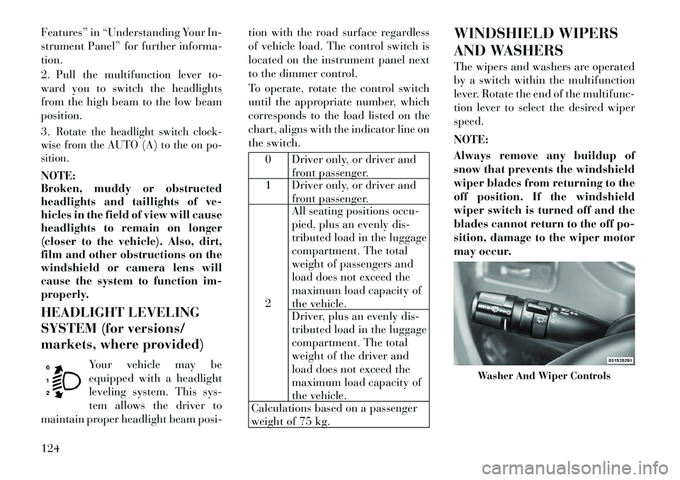
The wipers and washers are operated
by a switch within the multifunction
lever. Rotate the end of the multifunc-
tion lever to select the desired wiper
speed.
NOTE:
Always remove any buildup of
snow that prevents the windshield
wiper blades from returning to the
off position. If the windshield
wiper switch is turned off and the
blades cannot return to the off po-
sition, damage to the wiper motor
may occur.
Washer And Wiper Controls
124
Page 159 of 344

CAUTION!(Continued)
Do not use scrapers, sharp instru-
ments, or abrasive window clean-
ers on the interior surface of the
window.
Keep all objects a safe distance
from the window.
ROOF LUGGAGE RACK
(for versions/markets,
where provided)
The crossbars on your vehicle are de-
livered stowed within the roof rack
side rails. If adding cargo, deploy the
crossbars. Distribute cargo weight
evenly on the roof rack crossbars, to
maximum of 68 kg. The roof rack
does not increase the total load carry-
ing capacity of the vehicle. Be sure the
total load of cargo inside the vehicle
plus that on the external rack does not
exceed the maximum vehicle load ca-
pacity. The crossbars and side rails are de-
signed to carry weight on vehicles
equipped with a luggage rack. The
load must not exceed 68 kg, and
should be uniformly distributed over
the luggage rack crossbars.
NOTE:
Crossbars are error-proofed and
cannot be deployed or stowed in
the incorrect positions.
To help control wind noise, stow the crossbars in the side rails
when they are not in use. DEPLOYING THE
CROSSBARS
To deploy the crossbars, completely
loosen the thumb screws at both ends
of the crossbar and lift the crossbar
from its stowed position in the side
rail. Repeat with crossbar on the op-
posite side.
CAUTION!
Use care when removing and han-
dling the crossbars to prevent dam-
age to the vehicle.
Crossbar Stowed In Side Rail
Loosening Crossbars
153
Page 161 of 344

Stowing the Crossbars
Reverse the procedure to stow the
crossbars, again, taking care to keep
hand clear of pivoting joint. Crossbars
are identical and can be stowed in
either rail nest. Once the crossbars are
stowed, tighten the thumb screws
completely.
NOTE:
Load should always be secured to
crossbars first, with rail tie down
loops used as additional securing
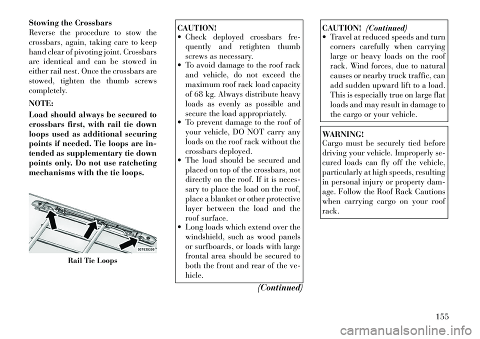
points if needed. Tie loops are in-
tended as supplementary tie down
points only. Do not use ratcheting
mechanisms with the tie loops.
CAUTION!
Check deployed crossbars fre-quently and retighten thumb
screws as necessary.
To avoid damage to the roof rack
and vehicle, do not exceed the
maximum roof rack load capacity
of 68 kg. Always distribute heavy
loads as evenly as possible and
secure the load appropriately.
To prevent damage to the roof of
your vehicle, DO NOT carry any
loads on the roof rack without the
crossbars deployed.
The load should be secured and
placed on top of the crossbars, not
directly on the roof. If it is neces-
sary to place the load on the roof,
place a blanket or other protective
layer between the load and the
roof surface.
Long loads which extend over the
windshield, such as wood panels
or surfboards, or loads with large
frontal area should be secured to
both the front and rear of the ve-
hicle.
(Continued)
CAUTION!(Continued)
Travel at reduced speeds and turn
corners carefully when carrying
large or heavy loads on the roof
rack. Wind forces, due to natural
causes or nearby truck traffic, can
add sudden upward lift to a load.
This is especially true on large flat
loads and may result in damage to
the cargo or your vehicle.WARNING!
Cargo must be securely tied before
driving your vehicle. Improperly se-
cured loads can fly off the vehicle,
particularly at high speeds, resulting
in personal injury or property dam-
age. Follow the Roof Rack Cautions
when carrying cargo on your roof
rack.
Rail Tie Loops
155
Page 252 of 344

TIRE PRESSURES FOR
HIGH-SPEED OPERATION
The manufacturer advocates driving
at safe speeds within posted speed
limits. Where speed limits or condi-
tions are such that the vehicle can be
driven at high speeds, maintaining
correct tire inflation pressure is very
important. Increased tire pressure
and reduced vehicle loading may be
required for high-speed vehicle op-
eration. Refer to original-equipment
information, or an authorized tire
dealer, for recommended safe operat-
ing speeds, loading and cold tire infla-
tion pressures.WARNING!
High-speed driving, with your ve-
hicle at or above maximum load, is
dangerous. The added strain on your
tires could cause them to fail. You
could have a serious collision. Do not
drive a vehicle loaded to the maxi-
mum capacity at continuous speeds
above 120 km/h.RADIAL-PLY TIRES
WARNING!
Combining radial ply tires with
other types of tires on your vehicle
will cause your vehicle to handle
poorly. The instability could cause a
collision. Always use radial ply tires
in sets of four. Never combine them
with other types of tires.
Cuts and punctures in radial tires are
repairable only in the tread area be-
cause of sidewall flexing. Consult
your authorized tire dealer for radial
tire repairs.
SPARE TIRE MATCHING
ORIGINAL EQUIPPED
TIRE AND WHEEL (for
versions/markets, where
provided)
Your vehicle may be equivalent with a
spare tire and wheel in look and func-
tion as the original equipment tire and
wheel found on the front or rear axle
of your vehicle. This spare tire may be
used in the tire rotation for your ve-
hicle. If your vehicle has this option refer to an authorized tire dealer for
the recommended tire rotation pat-
tern.
If your vehicle is not equipped with an
original equipment tire and wheel as a
spare, a non-matching temporary
emergency use spare may be equipped
with your vehicle. Temporary use
spares are engineered to be used only
with your vehicle. Your vehicle may
be equipped with one of the following
types of non-matching temporary use
spares; compact, full size, or limited-
use. Do not install more than one non-
matching temporary use spare tire/
wheel on the vehicle at any given time.
CAUTION!
Because of the reduced ground clear-
ance, do not take your vehicle
through an automatic car wash with
a compact, full size or limited-use
temporary spare installed. Damage
to the vehicle may result.
246
Page 255 of 344

REPLACEMENT TIRES
The tires on your new vehicle provide
a balance of many characteristics.
They should be inspected regularly
for wear and correct cold tire inflation
pressure. The manufacturer strongly
recommends that you use tires
equivalent to the originals in size,
quality and performance when re-
placement is needed. Please see
“Tread Wear Indicators” and “Tire
and Loading Information” placard
for the size designation of your tire.
The Load Index and Speed Symbol
for your tire will be found on the
original equipment tire sidewall. See
the Tire Sizing Chart example found
in the Tire Safety Information section
of this manual for more information
relating to the Load Index and Speed
Symbol of a tire.
It is recommended to replace the two
front tires or two rear tires as a pair.
Replacing just one tire can seriously
affect your vehicle’s handling. If you
ever replace a wheel, make sure that
the wheel’s specifications match those
of the original wheels.It is recommended you contact your
original equipment or an authorized
tire dealer with any questions you
may have on tire specifications or ca-
pability. Failure to use equivalent re-
placement tires may adversely affect
the safety, handling, and ride of your
vehicle.
WARNING!
Do not use a tire, wheel size or
rating other than that specified
for your vehicle. Some combina-
tions of unapproved tires and
wheels may change suspension di-
mensions and performance char-
acteristics, resulting in changes to
steering, handling, and braking of
your vehicle. This can cause un-
predictable handling and stress to
steering and suspension compo-
nents. You could lose control and
have a collision resulting in seri-
ous injury or death. Use only the
tire and wheel sizes with load rat-
ings approved for your vehicle.
(Continued)
WARNING!(Continued)
Never use a tire with a smaller
load index or capacity, than what
was originally equipped on your
vehicle. Using a tire with a smaller
load index could result in tire
overloading and failure. You
could lose control and have a col-
lision.
Failure to equip your vehicle with
tires having adequate speed capa-
bility can result in sudden tire fail-
ure and loss of vehicle control.CAUTION!
Replacing original tires with tires of
a different size may result in false
speedometer and odometer read-
ings.
TIRE CHAINS
Use of Security Chain Company
(SCC) Super Z6 SZ-143 or Iceman
Z6 IZ-643 cables or equivalent are
recommended on 225/65R17 tires.
NOTE:
Do not use tire chains on a com-
pact spare tire.
249
Page 266 of 344

Gross Trailer Weight (GTW)
The GTW is the weight of the trailer
plus the weight of all cargo, consum-
ables and equipment (permanent or
temporary) loaded in or on the trailer
in its "loaded and ready for opera-
tion" condition. The recommended
way to measure GTW is to put your
fully loaded trailer on a vehicle scale.
The entire weight of the trailer must
be supported by the scale.
Gross Combination Weight Rating
(GCWR)
The GCWR is the total permissible
weight of your vehicle and trailer
when weighed in combination.
NOTE:
The GCWR rating includes a 68 kg
allowance for the presence of a
driver.
Gross Axle Weight Rating (GAWR)
The GAWR is the maximum capacity
of the front and rear axles. Distribute
the load over the front and rear axles
evenly. Make sure that you do not
exceed either front or rear GAWR.
WARNING!
It is important that you do not ex-
ceed the maximum front or rear
GAWR. A dangerous driving condi-
tion can result if either rating is ex-
ceeded. You could lose control of the
vehicle and have an accident.
Trailer Tongue Weight (TW)
The tongue weight is the downward
force exerted on the hitch ball by the
trailer. In most cases, it should not be
less than 7% or more than 10% of the
trailer load. Trailer tongue weight
must not exceed the lesser of either the
hitch certification rating, or the trailer
tongue chassis rating. It should never
be less than 4% of the trailer load, and
not less than 25 kg. You must consider
tongue load as part of the load on your
vehicle and its GAWR.
WARNING!
An improperly adjusted hitch sys-
tem may reduce handling, stability
and braking performance and could
result in an accident. Consult with
your hitch and trailer manufacturer
or a reputable trailer/caravan dealer
for additional information.
Frontal Area
The frontal area is the maximum
height multiplied by the maximum
width of the front of a trailer.
BREAKAWAY CABLE
ATTACHMENT
European braking regulations for
braked trailers up to 3 500 kg, require
trailers to be fitted with either a sec-
ondary coupling or breakaway cable.
The recommended location for at-
taching the normal trailer's break-
away cable is in the stamped slot lo-
cated on the sidewall of the hitch
receiver.
260
Page 269 of 344

WARNING!(Continued)
Vehicles with trailers should not
be parked on a grade. When park-
ing, apply the parking brake on
the tow vehicle. Put the tow ve-
hicle automatic transmission in
PARK. Always block or "chock"
the trailer wheels.
GCWR must not be exceeded.
Total weight must be distrib-
uted between the tow vehicle
and the trailer such that the
following four ratings are not
exceeded:
1. GVWR
2. GTW
3. GAWR
4. Trailer tongue weight rating for
the trailer hitch utilized.
Towing Requirements – Tires
Do not attempt to tow a trailer while using a compact spare tire.
Proper tire inflation pressures are essential for the safe and satisfac-
tory operation of your vehicle. Re-
fer to “Tires – General Informa-
tion” in “Starting and Operating”
for proper tire inflation procedures. Check the trailer tires for proper
tire inflation pressures before
trailer usage.
Check for signs of tire wear or vis- ible tire damage before towing a
trailer. Refer to “Tires – General
Information” in “Starting and Op-
erating” for the proper inspection
procedure.
When replacing tires, refer to “Tires – General Information” in “Start-
ing and Operating” for proper tire
replacement procedures. Replacing
tires with a higher load carrying
capacity will not increase the vehi-
cle's GVWR and GAWR limits.
Towing Requirements – Trailer
Brakes
Do notinterconnect the hydraulic
brake system or vacuum system of
your vehicle with that of the trailer.
This could cause inadequate brak-
ing and possible personal injury.
When towing a trailer equipped with a hydraulic surge actuated
brake system, an electronic brake
controller is not required. Trailer brakes are recommended
for trailers over 450 kg and re-
quired for trailers in excess of
750 kg.
CAUTION!
If the trailer weighs more than
450 kg loaded, it should have its
own brakes and they should be of
adequate capacity. Failure to do this
could lead to accelerated brake lin-
ing wear, higher brake pedal effort,
and longer stopping distances.WARNING!
Do not connect trailer brakes to
your vehicle's hydraulic brake
lines. It can overload your brake
system and cause it to fail. You
might not have brakes when you
need them and could have an ac-
cident.
Towing any trailer will increase
your stopping distance. When
towing you should allow for addi-
tional space between your vehicle
and the vehicle in front of you.
Failure to do so could result in an
accident.
263
Page 333 of 344

Bulbs, Light . . . . . . . . . . . 65,308
Calibration, Compass . . . 172,181
Camera, Rear . . . . . . . . . . . . 135
Capacities, Fluid . . . . . . . . . . 311
Caps, FillerFuel . . . . . . . . . . . . . . . . . 258
Oil (Engine) . . . . . . . . . . . . 286
Power Steering . . . . . . . . . . 238
Radiator (Coolant
Pressure) . . . . . . . . . . . . . . 297
Car Washes . . . . . . . . . . . . . . 301
Carbon Monoxide Warning . . . . 63
Cargo (Vehicle Loading) . . . . . 148
Cargo Compartment Luggage Carrier . . . . . . . . . 153
Caution, Exhaust Gas . . . . . . . 33
Cellular Phone . . . . . . . . . 82,208
Center High Mounted Stop
Light . . . . . . . . . . . . . . . . . . 311
Chains, Tire . . . . . . . . . . . . . 249
Changing A Flat Tire . . . . . . . 269
Check Engine Light
(Malfunction Indicator
Light) . . . . . . . . . . . . . . . . . . 166
Checking Your Vehicle For
Safety . . . . . . . . . . . . . . . . . . . 63
Checks, Safety . . . . . . . . . . . . . 63
Child Restraint . . . . . . . . 53,56,57 Child Restraint Tether
Anchors . . . . . . . . . . . . . . . . . 58
Child Safety Locks . . . . . . . . . . 31
Child Seat . . . . . . . . . . . . . . . . 62
Clean Air Gasoline . . . . . . . . . 257
Cleaning
Wheels . . . . . . . . . . . . . . . 302
Climate Control . . . . . . . . . . . 209
Coat Hook . . . . . . . . . . . . . . 148
Coin Holder . . . . . . . . . . . . . 148
Cold Weather Operation . . . . . 227
Compact Disc (CD)
Maintenance . . . . . . . . . . . . . 208
Compact Spare Tire . . . . . . . . 247
Compass . . . . . . . . . 170,172,180
Compass Calibration . . . . 172,181
Compass Variance . . . . . . 170,181
Computer, Trip/Travel . . . . . . 179
Connector
UCI . . . . . . . . . . . . . . . . . . 187
Universal Consumer
Interface (UCI) . . . . . . . . . . 187
Conserving Fuel . . . . . . . . . . . 178
Console . . . . . . . . . . . . . . . . . 148
Console, Floor . . . . . . . . . . . . 148
Console, Overhead . . . . . . . . . 136
Console, Removable . . . . . . . . 150
Cool Down, Turbo . . . . . . . . . 229 Coolant Pressure Cap
(Radiator Cap) . . . . . . . . . . . 297
Cooling System . . . . . . . . . . . 295
Adding Coolant
(Antifreeze) . . . . . . . . . . . . 296
Coolant Capacity . . . . . . . . 311
Coolant Level . . . . . . . 295,297
Disposal of Used Coolant . . . 297
Drain, Flush, and Refill . . . . 296
Inspection . . . . . . . . . . . . . 297
Points to Remember . . . . . . 298
Pressure Cap . . . . . . . . . . . 297
Radiator Cap . . . . . . . . . . . 297
Selection of Coolant
(Antifreeze) . . . . . 296,311,312
Cupholders . . . . . . . . . . . 144,303
Data Recorder, Event . . . . . . . . 52
Defroster, Rear Window . . . . . 152
Defroster, Windshield . . . . 64,217
Diagnostic System, Onboard . . 287
Diesel Fuel . . . . . . . . . . . 258,312
Diesel Fuel Requirements . . . . 258
Dimmer Control . . . . . . . . . . 120
Dipsticks Automatic Transaxle . . . . . . 300
Oil (Engine) . . . . . . . . . . . . 288
Power Steering . . . . . . . . . . 238
Disabled Vehicle Towing . . . . . 281
327