Lancia Voyager 2014 Owner handbook (in English)
Manufacturer: LANCIA, Model Year: 2014, Model line: Voyager, Model: Lancia Voyager 2014Pages: 364, PDF Size: 3.49 MB
Page 331 of 364

WARNING!(Continued)
Before replacing a fuse, makesure that the ignition is off and
that all the other services are
switched off and/or disengaged.
If the replaced fuse blows again, contact an authorized dealer.
If a general protection fuse for safety systems (air bag system,
braking system), power unit sys-
tems (engine system, gearbox sys-
tem) or steering system blows,
contact an authorized dealer.
TOTALLY INTEGRATED
POWER MODULE
The Totally Integrated Power Module
is located in the engine compartment
near the battery. Refer to the appli-
cable “Engine Compartment” illus-
tration in this section. This center
contains cartridge fuses and mini-
fuses. A label that identifies each component may be printed or em-
bossed on the inside of the cover.
CAUTION!
When installing the Totally Inte-
grated Power Module cover, it is
important to ensure the cover is
properly positioned and fully
latched. Failure to do so may al-
low water to get into the Inte-
grated Power Module, and possi-
bly result in a electrical system
failure.
(Continued)
CAUTION!(Continued)
When replacing a blown fuse, it isimportant to use only a fuse hav-
ing the correct amperage rating.
The use of a fuse with a rating
other than indicated may result in
a dangerous electrical system
overload. If a properly rated fuse
continues to blow, it indicates a
problem in the circuit that must
be corrected.
The numbers inside the TIPM cover
correspond to the following table.
FUSES/TIPM
Cavity Cartridge Fuse Mini-Fuse Description J1 40 Amp Green — Power Folding Seat
J2 30 Amp Pink — Power Liftgate Module
Totally Integrated Power Module
325
Page 332 of 364

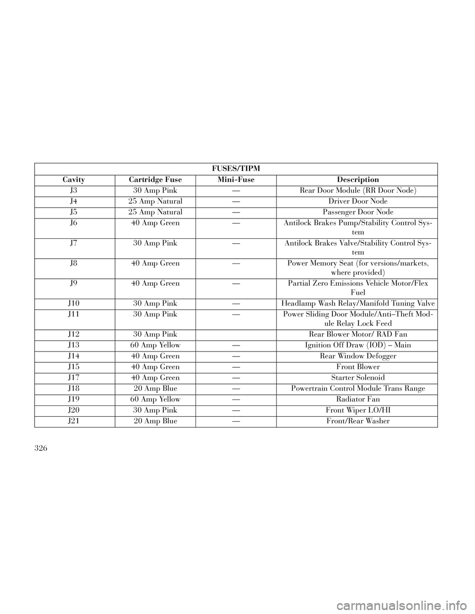
FUSES/TIPM
Cavity Cartridge Fuse Mini-Fuse Description J3 30 Amp Pink — Rear Door Module (RR Door Node)
J4 25 Amp Natural — Driver Door Node
J5 25 Amp Natural — Passenger Door Node
J6 40 Amp Green — Antilock Brakes Pump/Stability Control Sys- tem
J7 30 Amp Pink — Antilock Brakes Valve/Stability Control Sys- tem
J8 40 Amp Green — Power Memory Seat (for versions/markets, where provided)
J9 40 Amp Green — Partial Zero Emissions Vehicle Motor/Flex Fuel
J10 30 Amp Pink —Headlamp Wash Relay/Manifold Tuning Valve
J11 30 Amp Pink —Power Sliding Door Module/Anti–Theft Mod-
ule Relay Lock Feed
J12 30 Amp Pink Rear Blower Motor/ RAD Fan
J13 60 Amp Yellow —Ignition Off Draw (IOD) – Main
J14 40 Amp Green —Rear Window Defogger
J15 40 Amp Green — Front Blower
J17 40 Amp Green —Starter Solenoid
J18 20 Amp Blue —Powertrain Control Module Trans Range
J19 60 Amp Yellow — Radiator Fan
J20 30 Amp Pink —Front Wiper LO/HI
J21 20 Amp Blue —Front/Rear Washer
326
Page 333 of 364

FUSES/TIPM
Cavity Cartridge Fuse Mini-Fuse Description J22 25 Amp Natural — Sunroof ModuleM1 — 15 Amp Blue Rear Center Brake Lamp/Brake Switch
M2 — 20 Amp Yellow Trailer Lighting/Fog Lamps
M3 — 20 Amp Yellow Front/Rear Axle Locker/Vacuum Pump Motor
M4 — 10 Amp Red Trailer Tow
M5 — 25 Amp Natural Inverter
M6 — 20 Amp Yellow Power Outlet #1 (ACC), Rain Sensor
M7 — 20 Amp Yellow Power Outlet #2 (BATT/ACC SELECT)
M8 — 20 Amp Yellow Front Heated Seat (for versions/markets, where provided)
M9 — 20 Amp Yellow Rear Heated Seat (for versions/markets, where provided)
M10 —15 Amp Blue Ignition Off Draw — Video System, DVD,
Hands-Free Module, Vanity Lamp, StreamingVideo Module
M11 —10 Amp Red Ignition Off Draw – Climate Control System
M12 —30 Amp Green Amplifier (AMP)/Radio
M13 —20 Amp Yellow Ignition Off Draw— Instrument Cluster, SI-
REN, Clock Module, Multi-Function ControlSwitch/ITM
M14 —20 Amp Yellow Spare Fuse
327
Page 334 of 364

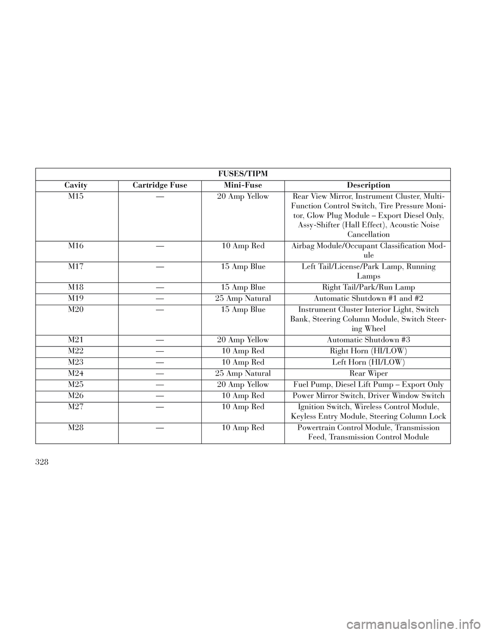
FUSES/TIPM
Cavity Cartridge Fuse Mini-Fuse Description M15 — 20 Amp Yellow Rear View Mirror, Instrument Cluster, Multi- Function Control Switch, Tire Pressure Moni-tor, Glow Plug Module – Export Diesel Only, Assy-Shifter (Hall Effect), Acoustic Noise Cancellation
M16 —10 Amp Red Airbag Module/Occupant Classification Mod-
ule
M17 —15 Amp Blue Left Tail/License/Park Lamp, Running
Lamps
M18 —15 Amp Blue Right Tail/Park/Run Lamp
M19 —25 Amp Natural Automatic Shutdown #1 and #2
M20 —15 Amp Blue Instrument Cluster Interior Light, Switch
Bank, Steering Column Module, Switch Steer-ing Wheel
M21 —20 Amp Yellow Automatic Shutdown #3
M22 —10 Amp Red Right Horn (HI/LOW)
M23 —10 Amp Red Left Horn (HI/LOW)
M24 —25 Amp Natural Rear Wiper
M25 —20 Amp Yellow Fuel Pump, Diesel Lift Pump – Export Only
M26 —10 Amp Red Power Mirror Switch, Driver Window Switch
M27 —10 Amp Red Ignition Switch, Wireless Control Module,
Keyless Entry Module, Steering Column Lock
M28 —10 Amp Red Powertrain Control Module, Transmission
Feed, Transmission Control Module
328
Page 335 of 364

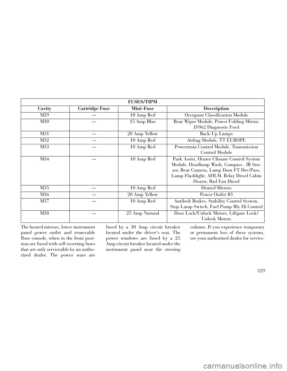
FUSES/TIPM
Cavity Cartridge Fuse Mini-Fuse Description M29 — 10 Amp Red Occupant Classification Module
M30 — 15 Amp Blue Rear Wiper Module, Power Folding Mirror, J1962 Diagnostic Feed
M31 — 20 Amp Yellow Back-Up Lamps
M32 — 10 Amp Red Airbag Module, TT EUROPE
M33 — 10 Amp Red Powertrain Control Module, Transmission Control Module
M34 — 10 Amp Red Park Assist, Heater Climate Control System Module, Headlamp Wash, Compass , IR Sen-sor, Rear Camera, Lamp Door FT Drv/Pass,
Lamp Flashlight, AHLM, Relay Diesel Cabin Heater, Rad Fan Diesel
M35 — 10 Amp Red Heated Mirrors
M36 — 20 Amp Yellow Power Outlet #3
M37 — 10 Amp Red Antilock Brakes, Stability Control System, Stop Lamp Switch, Fuel Pump Rly Hi Control
M38 — 25 Amp Natural Door Lock/Unlock Motors, Liftgate Lock/ Unlock Motors
The heated mirrors, lower instrument
panel power outlet and removable
floor console, when in the front posi-
tion are fused with self-resetting fuses
that are only serviceable by an autho-
rized dealer. The power seats are fused by a 30 Amp circuit breaker
located under the driver's seat. The
power windows are fused by a 25
Amp circuit breaker located under the
instrument panel near the steering
column. If you experience temporary
or permanent loss of these systems,
see your authorized dealer for service.
329
Page 336 of 364

VEHICLE STORAGE
If you are leaving your vehicle dor-
mant for more than 21 days, you may
want to take steps to protect your
battery. You may do the following:
Remove the 60 Amp cartridge inthe Totally Integrated Power Mod-
ule (TIPM) labeled Ignition-Off
Draw (IOD).
Or, disconnect the negative cable from the battery.
Anytime you store your vehicle, or keep it out of service for two weeks
or more, run the air conditioning
system at idle for about five min-
utes in the fresh air and high blower
setting. This will ensure adequate
system lubrication to minimize the
possibility of compressor damage
when the system is started again.
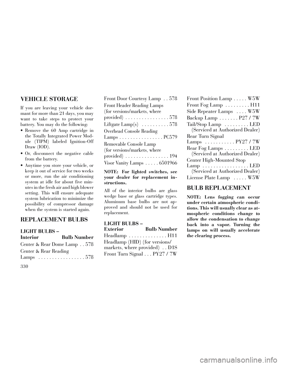
REPLACEMENT BULBS
LIGHT BULBS –
Interior Bulb Number
Center & Rear Dome Lamp . . 578
Center & Rear Reading
Lamps .................578 Front Door Courtesy Lamp . . 578
Front Header Reading Lamps
(for versions/markets, where
provided)
................578
Liftgate Lamp(s) ..........578
Overhead Console Reading
Lamps ................ PC579
Removable Console Lamp
(for versions/markets, where
provided) ................194
Visor Vanity Lamps .....6501966
NOTE: For lighted switches, see
your dealer for replacement in-
structions.
All of the interior bulbs are glass
wedge base or glass cartridge types.
Aluminum base bulbs are not ap-
proved and should not be used for
replacement.
LIGHT BULBS –
Exterior Bulb Number
Headlamp . . ............H11
Headlamp (HID) (for versions/
markets, where provided) . . D1S
Front Turn Signal . . . PY27 / 7W Front Position Lamp . . . . . W5W
Front Fog Lamp . . . .
.....H11
Side Repeater Lamps . . . . W5W
Backup Lamp . . .....P27/7W
Tail/Stop Lamp . ........LED
(Serviced at Authorized Dealer)
Rear Turn Signal
Lamps ........... PY27 / 7W
Rear Fog Lamps . . .......LED
(Serviced at Authorized Dealer)
Center High-Mounted Stop
Lamp .................LED
(Serviced at Authorized Dealer)
License Plate Lamp .....W5W
BULB REPLACEMENT
NOTE: Lens fogging can occur
under certain atmospheric condi-
tions. This will usually clear as at-
mospheric conditions change to
allow the condensation to change
back into a vapor. Turning the
lamps on will usually accelerate
the clearing process.
330
Page 337 of 364

CAUTION!
Where possible, it is advisable to
have bulbs changed at a LANCIA
Dealership. Proper operation and
orientation of the external lights are
essential for driving safety and
complying with the law.
HIGH INTENSITY
DISCHARGE HEADLAMPS
(HID) (for versions/markets,
where provided)
The headlamps are a type of high
voltage discharge tube. High voltage
can remain in the circuit even with the
headlamp switch off and the key re-
moved.Because of this, you should
not attempt to service a headlamp
bulb yourself. If a headlamp bulb
fails, take your vehicle to an au-
thorized dealer for service.
WARNING!
A transient high voltage occurs at
the bulb sockets of High Intensity
Discharge (HID) headlamps when
the headlamp switch is turned ON.
It may cause serious electrical
shock or electrocution if not ser-
viced properly. See your authorized
dealer for service.
NOTE: On vehicles equipped
with High Intensity Discharge
(HID) headlamps, when the head-
lamps are turned on, there is a
blue hue to the lamps. This dimin-
ishes and becomes more white af-
ter approximately 10 seconds, as
the system charges.
QUAD HEADLAMPS (for
versions/markets, where
provided)
1. Raise the hood to access the high
or low beam bulbs at the rear of the
headlamp housing.
2. Release the two tabs on the side of
the connector and remove the connec-
tor from the bulb. 3. Twist the headlamp bulb and pull
the bulb from the headlamp housing.
4. Install the new headlamp bulb and
twist until locked into the headlamp
housing.
CAUTION!
Do not touch the new bulb with
your fingers. Oil contamination will
severely shorten bulb life. If the
bulb comes in contact with an oily
surface, clean the bulb with rub-
bing alcohol.
5. Reconnect the wiring connector to
the bulb.
FRONT TURN SIGNAL AND
SIDE MARKER LAMPS
Access to change the turn signal or
side marker bulb is from the rear of
the headlamp housing.
1. Twist the turn signal or side
marker socket to remove the socket.
2. Pull bulb from the socket.
3. Replace the bulb and reinstall
socket. 331
Page 338 of 364

SIDE REPEATER LAMPS
The side repeater lamps are located in
both front fenders.
1. Push the side repeater lamp to the
right and release retaining tab on the
left.
2. Pull side repeater lamp out and
disengage bulb socket from lamp.
3. Press, then rotate and pull bulb
from socket.
4. Install bulb to socket.
5. Push the lamp socket into the side
repeater lamp.
6. Position metal spring clip in
fender hole notch.
7. Position side repeater lamp to hole
in fender.8. Push side repeater lamp to com-
press metal spring clip and seat re-
taining tab into fender.
FOG LAMPS
NOTE: Access to the fog lamp
bulb is from the rear of the fascia.
On the left rear side of the fascia,
remove the push pin and lower the
hinged access door on the air dam.
1. Remove access cover from under
bumper fascia.
2. Remove bulb from lamp.
3. Disconnect wire harness connec-
tor.
4. Remove the bulb from the connec-
tor socket and install the replacement
bulb.
CAUTION!
Do not touch the new bulb with
your fingers. Oil contamination will
severely shorten bulb life. If the
bulb comes in contact with an oily
surface, clean the bulb with rub-
bing alcohol.
5. Install the bulb and connector as-
sembly into the fog lamp housing.
6. Close and secure the access door
cover under bumper fascia.
REAR TURN SIGNAL AND
BACKUP LAMP
1. Raise the liftgate.
2. Remove the tail lamp assembly by
removing the two screws from the in-
board side. Use a fiber stick or similar
tool to gently pry the light on the
outboard side to disengage the two
ball studs.
NOTE:
If a screwdriver is used, make
sure a soft material is placed be-
tween the vehicle body and tool
so not to scratch the paint.
Side Repeater Bulb Replacement
332
Page 339 of 364

The PRY location is best closestto the studs while dislodging
them separately.
3. Twist the socket and remove it
from the lamp assembly.
4. Pull the bulb to remove it from the
socket.
5. Replace the bulb, reinstall the
socket, and reattach the lamp assem-
bly.CENTER HIGH-MOUNTED
STOP LAMP (CHMSL)
The CHMSL uses LED lights are not
serviceable. The CHMSL must be re-
placed as an assembly, see your au-
thorized dealer.
LICENSE LAMP
There are two license plate lamps, and
they are located under the tailgate
lamp bar and above the license plate. 1. Remove the two lens assembly
mounting screws.
2. Remove the bulb from the socket.
Replace the bulb and reattach the lens
assembly.
FLUID CAPACITIES
Metric
Fuel (Approximate) 76 Liters
Engine Oil with Filter
3.6L Engine 5.6 Liters
2.8L Diesel Engine 6.6 Liters
Cooling System *
3.6L Engine 12.6 Liters
2.8L Diesel Engine 13.8 Liters
* Includes heater and coolant recovery bottle filled to MAX level. Add 2.8 Liters for versions/markets, where provided
with a rear heater.
333
Page 340 of 364

FLUIDS, LUBRICANTS AND GENUINE PARTS
ENGINE
ComponentFluids and Lubricants Specs (Genuine Parts)
Engine Coolant* Red protective agent with antifreeze action, based on inhibited monoethyl gly-
col with organic formula. Exceeds CUNA NC 956-16, ASTM D 3306 specifica-
tions, FIAT Classification 9.55523 (PARAFLU UP Contractual Technical Ref-
erence N° F101.M01. Cooling circuit usage percentage: 50% water 50%
PARAFLU UP [**])
Engine Oil – 3.6L Engine*** SAE Grade 5W-20 fully synthetic engine oil that meets FIAT Classification
9.55535-CR1, API SN, ILSAC GF-5 (SELENIA K POWER, Contractual Tech-
nical Reference N° F042.F11)
Engine Oil – 2.8L Diesel Engine*** SAE Grade 5W-30 fully synthetic engine oil that meets FIAT Classification
9.55535-S3, API SM/CF, ACEA C3 (SELENIA MULTIPOWER C3, Contrac-
tual Technical Reference N° F102.F11)
Spark Plugs – 3.6L Engine We recommend you use OEM Original Equipment Spark Plugs (Gap 1.1 mm)
Fuel Selection – 3.6L Engine Research Octane Number (RON) of 91 or higher
Fuel Selection – 2.8L Diesel Engine 50 Cetane or higher (Less than 15 ppm Sulfur).
Diesel Fuel Additive – 2.8L Diesel
Engine Additive for diesel with antifreeze and protective action for diesel engines.
(TUTELA DIESEL ART, Contractual Technical Reference N° F601.L06. To be
mixed with the diesel fuel: 25 cc per 10 litres)
* Do not top up or mix with fluids
with different specifications.
** For particularly harsh climate con-
ditions, a mixture of 60% PARA-
FLUUP and 40% demineralised wa-
ter is recommended. *** Lubricants with ACEA C3 perfor-
mance as a minimum may be used for
Diesel engines in an emergency, where
no original products are available. In
such event, the engine may not pro-
vide optimal performance. We recom-
mend having the lubricant replacedwith one of the recommended lubri-
cants as soon as possible. Using prod-
ucts with specifications lower than
ILSAC GF-5 for gasoline engines or
lower than ACEA C3 for Diesel en-
gines may cause engine damage not
covered by warranty.
334