ESP Lancia Ypsilon 2011 Owner handbook (in English)
[x] Cancel search | Manufacturer: LANCIA, Model Year: 2011, Model line: Ypsilon, Model: Lancia Ypsilon 2011Pages: 299, PDF Size: 13.35 MB
Page 170 of 299

CHANGING A BULBGENERAL INSTRUCTIONS
❒Before changing a bulb check the contacts for
oxidation;
❒Burnt bulbs must be replaced by others of the
same type and power;
❒after replacing a headlight bulb, always check
its alignment;
❒when a light is not working, check that the
corresponding fuse is intact before changing
a bulb. For the location of fuses, refer to the
paragraph “If a fuse blows” in this section;
WARNING
Modifications or repairs to the
electric system that
are not carried
out properly or do not take the system
technical specifications into account can
cause malfunctions leading to the risk of
fire.
WARNING
Halogen bulbs contain pressurised
gas, in the
case of breakage they may
burst.
Halogen bulbs must be handled
holding the metallic part only.
Touching the transparent part of the
bulb with your fingers may reduce the
intensity of the emitted light and even reduce
the lifespan of the bulb. In case of accidental
contact, wipe the bulb with a cloth moistened
with alcohol and let the bulb dry.If possible, we recommend that you
have bulbs replaced at a Lancia
Dealership. The correct operation and
aiming of the outer lights are absolutely
essential for the safety of the car and of
compliance with law.Due to the high supply voltage, Xenon
gas-discharge bulbs (for versions/
markets, where provided) must only be
replaced by a specialist technician: danger of
death! Contact a Lancia Dealership.
168
GETTING TO KNOW
YOUR CAR
SAFETY
STARTING AND
DRIVING
WARNING LIGHTS
AND MESSAGESIN AN EMERGENCYSERVICING AND
MAINTENANCE
TECHNICAL
SPECIFICA
TIONS
INDEX
Page 180 of 299

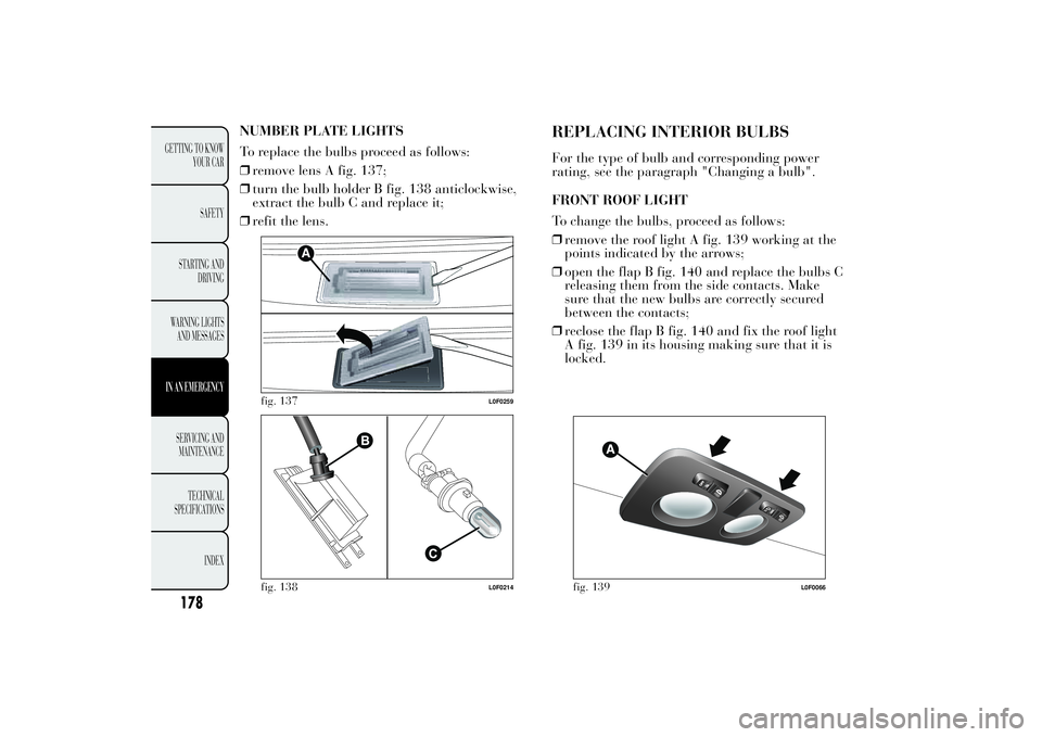
NUMBER PLATE LIGHTS
To replace the bulbs proceed as follows:
❒remove lens A fig. 137;
❒turn the bulb holder B fig. 138 anticlockwise,
extract the bulb C and replace it;
❒refit the lens.
REPLACING INTERIOR BULBSFor the type of bulb and corresponding power
rating, see the paragraph "Changing a bulb".
FRONT ROOF LIGHT
To change the bulbs, proceed as follows:
❒remove the roof light A fig. 139 working at the
points indicated by the arrows;
❒open the flap B fig. 140 and replace the bulbs C
releasing them from the side contacts. Make
sure that the new bulbs are correctly secured
between the contacts;
❒reclose the flap B fig. 140 and fix the roof light
A fig. 139 in its housing making sure that it is
locked.
fig. 137
L0F0259
fig. 138
L0F0214
fig. 139
L0F0066
178
GETTING TO KNOW
YOUR CAR
SAFETY
STARTING AND
DRIVING
WARNING LIGHTS
AND MESSAGESIN AN EMERGENCYSERVICING AND
MAINTENANCE
TECHNICAL
SPECIFICA
TIONS
INDEX
Page 185 of 299

FUSE LOCATION
Engine compartment fuse box
This is located next to the battery: to access fuses
proceed as follows:
❒move the cover A fig. 148 aside;
❒undo the screw A fig. 149, free the tabs B and
pull the cover upwards C. The ID number of
the electrical component corresponding to each
fuse can be found on the back of the cover.
After replacing the fuse, make sure that you
have closed cover C correctly on the fuse box.
If you need to wash the engine
compartment, take care not to directly
hit the fuse box and the window wiper
motors with the water jet.
fig. 148
L0F0170
fig. 149
L0F0094
183GETTING TO KNOW
YOUR CAR
SAFETY
STARTING AND
DRIVING
WARNING LIGHTS
AND MESSAGESIN AN EMERGENCYSERVICING AND
MAINTENANCE
TECHNICAL
SPECIFICA
TIONS
INDEX
Page 197 of 299

WARNING
Before towing, turn the ignition key to
MAR and then
to STOP without
removing it. The steering column will
automatically lock when the key is removed
and the wheels cannot be steered.
WARNING
Before tightening the hook clean the
threaded housing thoroughly
. Make
sure that the hook is fully fastened in the
housing before towing the car.
WARNING
Whilst towing, remember that as the
assistance of the
brake servo and
the electric power assisted steering is not
available, greater force needs to be exerted
on the brake pedal and more effort is
required on the steering wheel. Do not use
flexible cables when towing and avoid jerky
movements. During towing, make sure that
the trailer hitch does not damage any
components it is touching. When towing the
car, it is compulsory to respect specific
highway code regulations relating to the tow
hook and procedures for towing on the
road. Do not start the engine while towing
the car.
fig. 157
L0F0022
195GETTING TO KNOW
YOUR CAR
SAFETY
STARTING AND
DRIVING
WARNING LIGHTS
AND MESSAGESIN AN EMERGENCYSERVICING AND
MAINTENANCE
TECHNICAL
SPECIFICA
TIONS
INDEX
Page 198 of 299

WARNING
The front and rear tow hooks should
be used only
for emergencies on
the road. You are allowed to tow the car for
short distances using an appropriate device
in accordance with the highway code (a rigid
bar), to move the vehicle on the road in
readiness for towing or transporting via a
breakdown vehicle. Tow hooks MUST NOT
be used to tow vehicles off the road or where
there are obstacles and/or for towing
operations using cables or other non-rigid
devices. Respecting the above conditions,
towing must take place with the two vehicles
(one towing, the other towed) aligned as
much as possible along the same centre line.
196
GETTING TO KNOW
YOUR CAR
SAFETY
STARTING AND
DRIVING
WARNING LIGHTS
AND MESSAGESIN AN EMERGENCYSERVICING AND
MAINTENANCE
TECHNICAL
SPECIFICA
TIONS
INDEX
Page 209 of 299

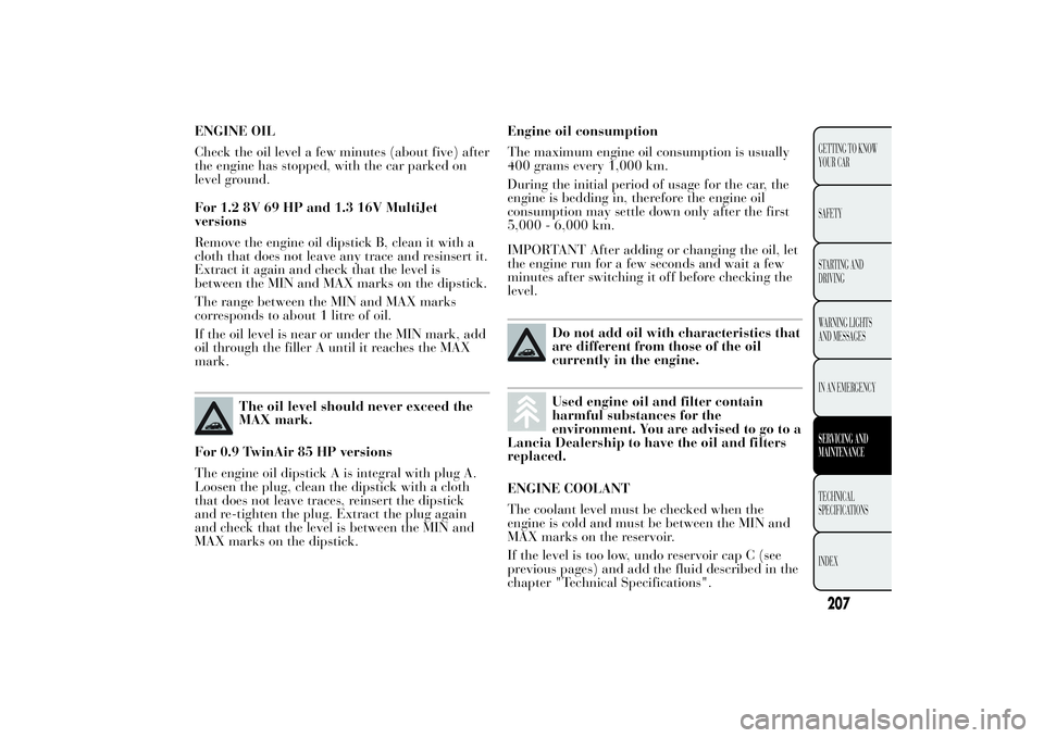
ENGINE OIL
Check the oil level a few minutes (about five) after
the engine has stopped, with the car parked on
level ground.
For 1.2 8V 69 HP and 1.3 16V MultiJet
versions
Remove the engine oil dipstick B, clean it with a
cloth that does not leave any trace and resinsert it.
Extract it again and check that the level is
between the MIN and MAX marks on the dipstick.
The range between the MIN and MAX marks
corresponds to about 1 litre of oil.
If the oil level is near or under the MIN mark, add
oil through the filler A until it reaches the MAX
mark.
The oil level should never exceed the
MAX mark.
For 0.9 TwinAir 85 HP versions
The engine oil dipstick A is integral with plug A.
Loosen the plug, clean the dipstick with a cloth
that does not leave traces, reinsert the dipstick
and re-tighten the plug. Extract the plug again
and check that the level is between the MIN and
MAX marks on the dipstick.Engine oil consumption
The maximum engine oil consumption is usually
400 grams every 1,000 km.
During the initial period of usage for the car, the
engine is bedding in, therefore the engine oil
consumption may settle down only after the first
5,000 - 6,000 km.
IMPORTANT After adding or changing the oil, let
the engine run for a few seconds and wait a few
minutes after switching it off before checking the
level.
Do not add oil with characteristics that
are different from those of the oil
currently in the engine.Used engine oil and filter contain
harmful substances for the
environment. You are advised to go to a
Lancia Dealership to have the oil and filters
replaced.
ENGINE COOLANT
The coolant level must be checked when the
engine is cold and must be between the MIN and
MAX marks on the reservoir.
If the level is too low, undo reservoir cap C (see
previous pages) and add the fluid described in the
chapter "Technical Specifications".
207GETTING TO KNOW
YOUR CAR
SAFETY
STARTING AND
DRIVING
WARNING LIGHTS
AND MESSAGES
IN AN EMERGENCYSERVICING AND
MAINTENANCETECHNICAL
SPECIFICA
TIONS
INDEX
Page 223 of 299

BODYWORK PAINT IDENTIFICATION PLATE
This is applied on the external (left side) luggage
compartment post and bears the following data
fig. 168:
APaint manufacturer.
BColour name.
CLancia colour code.
DRespray and touch up colour code.
CHASSIS MARKING
This is located on the right side of the luggage
compartment floor and gives the following
identification data:
❒type of vehicle
❒chassis serial number.ENGINE MARKING
This is stamped on the cylinder block and gives
the model and the chassis serial number.
fig. 168
L0F0030
221GETTING TO KNOW
YOUR CAR
SAFETY
STARTING AND
DRIVING
WARNING LIGHTS
AND MESSAGES
IN AN EMERGENCY
SERVICING AND
MAINTENANCETECHNICAL
SPECIFICA
TIONSINDEX
Page 225 of 299

ENGINEVersions 0.9 TwinAir 85 HP 1.2 8V 69 HP 1.3 16v MultiJet
Engine code 312A2000 169A4000 199B1000
Cycle Otto Otto Diesel
Number and arrangement of
2 in line 4 in line 4 in line
Piston diameter and travel (mm) 80.5 x 86.0 70.8 x 78.86 69.6 x 82
Total displacement (cm³) 875 1242 1248
Compression ratio 10 11,1 16,8
Maximum power (EEC) (kW)
62,5/57
(*)
51 70
Maximum power (EEC) (HP) 85 69 95
corresponding engine speed (rpm) 5500 5500 4000
Max torque (EEC) (Nm)
145/100
(*)
102 200
Maximum torque (EEC) (kgm) 14,8 10,4 20,4
corresponding engine speed (rpm)
1900 /2000
(*)
3000 1500
Spark plugs NGK PLKR9C8NGK ZKR7A-10 or
CHAMPION
RA8MCX4-
FuelUnleaded petrol 95
RON (Specification
EN228)Unleaded petrol 95
RON (Specification
EN228)Diesel for automotive
engines (Specification
EN590)
With ECO button pressed
223GETTING TO KNOW
YOUR CAR
SAFETY
STARTING AND
DRIVING
WARNING LIGHTS
AND MESSAGES
IN AN EMERGENCY
SERVICING AND
MAINTENANCETECHNICAL
SPECIFICA
TIONSINDEX
(*) cylinders
Page 230 of 299

Maximum speed ratingQ
up to 160 km/h
R
up to 170 km/h
Sup to 180 km/hTup to 190 km/hU
up to 200 km/h
H
up to 210 km/h
V
up to 240 km/h
Maximum speed index for snow tyres
QM+S
up to 160 km/h
TM+S
up to 190 km/h
HM+S
up to 210 km/h
Load rating (capacity)
70= 335 kg81= 462 kg
71= 345 kg82= 475 kg
72= 355 kg83= 487 kg
73= 365 kg84= 500 kg
74= 375 kg85= 515 kg
75= 387 kg86= 530 kg
76= 400 kg87= 545 kg
77= 412 kg88= 560 kg
78= 425 kg89= 580 kg
79= 437 kg90= 600 kg
80= 450 kg91= 615 kg
CORRECT READING OF THE WHEEL RIM
Example fig. 169:6Jx15H26rim diameter in inches (1).Jrim drop centre outline (side projection where
the tyre bead rests) (2).15
rim nominal diameter in inches (corresponds to
diameter of the tyre to be mounted) (3 = Ø).
H2
shape and number of humps (circumference
measurement which keeps the bead of tubeless
tyres in position on the rim).
228
GETTING TO KNOW
YOUR CAR
SAFETY
STARTING AND
DRIVING
WARNING LIGHTS
AND MESSAGES
IN AN EMERGENCY
SERVICING AND
MAINTENANCE
TECHNICAL
SPECIFICA
TIONS
INDEX
Page 237 of 299

WEIGHTS AND LOADSVersions 0.9 TwinAir 85 HP 1.2 8V 69 HP 1.3 16V MultiJet
Unladen weight (with all fluids, fuel
tank filled to 90% and without
optional equipment) (kg):975 965 1050
Payload including the driver (kg):(*)
480 (4-seater) / 535
(5-seater)480 (4-seater) / 535
(5-seater)480 (4-seater) / 535
(5-seater)
Maximum permitted loads (kg)
(**)
800 870 – front axle:
– rear axle: 810 810 810
– total:1455 (4-seater) / 1510
(5-seater)1445 (4-seater) / 1500
(5-seater)1530 (4-seater) / 1585
(5-seater)
Towable loads (kg)
750 750 – braked trailer:
– non-braked trailer: 400 400 400
Maximum load on roof: 55 55 55
Maximum load on the tow hook
(braked trailer) (kg):60 60 60
(*) If special equipment is fitted (sunroof, tow hitch, etc.) the unladen car weight increases, thus reducing the specified payload
with respect to the maximum permitted load.
(**) Loads not to be exceeded. The user is responsible for arranging goods in the luggage compartment and/or load carrying
platform within the maximum permitted loads.
235GETTING TO KNOW
YOUR CAR
SAFETY
STARTING AND
DRIVING
WARNING LIGHTS
AND MESSAGES
IN AN EMERGENCY
SERVICING AND
MAINTENANCETECHNICAL
SPECIFICA
TIONSINDEX
780
1000