sensor LAND ROVER DISCOVERY 1999 Workshop Manual
[x] Cancel search | Manufacturer: LAND ROVER, Model Year: 1999, Model line: DISCOVERY, Model: LAND ROVER DISCOVERY 1999Pages: 1529, PDF Size: 34.8 MB
Page 969 of 1529

INTERIOR TRIM COMPONENTS
76-3-4 REPAIRS
Trim casing - 'D' post
$% 76.13.73
Remove
1.Fold rear seat forward.
2.Remove tail door aperture upper trim casing.
3.Release caps from end of grab handle.
4.Remove 2 bolts securing grab handle to body.
5.Remove grab handle and collect two spacers.
6.Remove 8 trim clips securing trim casing to
body.
7. Models with third row seats:
aRemove third row seat belt escutcheon.
bRemove cap from lower anchorage of third
row seat belt.
cRemove lower anchorage bolt.8. Models with volumetric alarm:
aRelease volumetric sensor from trim casing.
bDisconnect multiplug from volumetric
sensor.
cRemove volumetric sensor.
9.Remove rear seat belt blanking plate.
10.Release 2 clips securing trim casing to body.
11.Remove trim casing.
Refit
1.Fit trim casing and secure with clips.
2.Fit rear seat belt blanking plate.
3. Models with volumetric alarm:
aPosition volumetric sensor to trim casing
and connect multiplug.
bFit volumetric sensor to trim casing.
4. Models with third row seats:
aFit lower anchorage of third row seat belt
and tighten bolt to 32 Nm (24 lbf.ft).
bFit cap to lower anchorage bolt.
cFit third row seat belt escutcheon to trim
casing.
5.Fit trim clips securing trim casing to body.
6.Position grab handle and spacers to trim
casing.
7.Fit and tighten bolts securing grab handle to
body to 3 Nm (2.2 lbf.ft).
8.Close caps on ends of grab handle.
9.Fit tail door aperture upper trim casing.
10.Reposition rear seat.
Page 979 of 1529

INTERIOR TRIM COMPONENTS
76-3-14 REPAIRS
Panel - auxiliary switch
$% 76.46.38
Remove
1.Carefully remove electric exterior mirror switch
from auxiliary switch panel and disconnect
multiplug.
2. Models with headlamp levelling: Release
knob and remove nut securing headlamp
levelling switch to auxiliary switch panel.
3.Release 2 fasteners and open fascia access
panel.
4. Models with headlamp levelling: Remove
headlamp levelling switch from auxiliary switch
panel and disconnect multiplug.
5. Models with A/C: Remove 2 screws securing
in-car temperature sensor to auxiliary switch
panel.
6. Models with A/C: Disconnect multiplug from
in-car temperature sensor and remove from
auxiliary switch panel.
7.Release 2 clips securing auxiliary switch panel
to fascia and remove panel.Refit
1.Position auxiliary switch panel to fascia and clip
into position.
2. Models with A/C: Connect multiplug to in-car
temperature sensor.
3. Models with A/C: Position in-car temperature
sensor to auxiliary switch panel and secure with
screws.
4. Models with headlamp levelling: Position
headlamp levelling switch to auxiliary switch
panel and secure with nut.
5. Models with headlamp levelling: Replace
cap and connect multiplug to headlamp
levelling switch.
6.Connect multiplug to exterior mirror switch and
fit switch to auxiliary switch panel.
Page 986 of 1529

INTERIOR TRIM COMPONENTS
REPAIRS 76-3-21
11.Remove access panel from front edge of front
stowage pocket.
12.Remove screw securing front stowage pocket
to headlining.
13.Remove lens from front interior lamp.
14.Remove 2 nuts securing front interior lamp to
headlining.
15.Disconnect multiplug from front interior lamp.
16.Remove front interior lamp.
17.Remove 10 screws securing front stowage
pocket to headlining.
18.Disconnect 3 multiplugs from sunroof switches.
19.Remove front stowage pocket.
20.Remove caps from sun visor clips.
21.Remove screws and release both sun visor
clips.
22.Remove tail door aperture upper trim casing.
23.Remove rear sunroof aperture trim. 24.Remove front sunroof aperture trim.
25.Release end caps from all grab handles.
26.Remove 2 bolts securing each grab handle to
roof.
27.Remove all 4 grab handles.
28. Models with volumetric alarm: Release front
volumetric sensor from headlining and
disconnect multiplug.
29. Models with rear A/C:
aRelease rear A/C control panel from
headlining.
bDisconnect 2 multiplugs and 2 Lucar
connectors from rear A/C control panel.
cRemove rear A/C control panel.
30.Release rear interior lamp from headlining and
disconnect multiplug.
31.Remove rear interior lamp.
Page 988 of 1529

INTERIOR TRIM COMPONENTS
REPAIRS 76-3-23
11.Position rear interior lamp to headlining and
connect multiplug.
12.Fit rear interior lamp to headlining.
13. Models with rear A/C:
aPosition rear A/C control panel to headlining
and connect multiplugs and Lucar
connectors.
bFit rear A/C control panel to headlining.
14. Models with volumetric alarm: Connect
multiplug to front volumetric sensor and fit
sensor to headlining.
15.Fit grab handles to headlining and secure with
bolts.
16.Fit end caps to grab handles.
17.Fit front sunroof aperture trim.
18.Fit rear sunroof aperture trim.
19.Fit tail door aperture upper trim casing.
20.Fit sun visor clips to headlining and secure with
screws.
21.Fit caps to sun visor clips.
22.Position front stowage pocket to headlining and
connect multiplugs to sunroof switches.
23.Fit and tighten 10 screws securing front
stowage pocket to headlining.
24.Connect multiplug to front interior lamp.
25.Fit front interior lamp to headlining and secure
with nuts.
26.Fit lens to front interior lamp.
27.Fit and tighten screw securing front stowage
pocket to headlining.
28.Fit access panel to front edge of front stowage
pocket.
29.Position sun visor to headlining and secure to
clip.
30.Connect multiplug to sun visor.
31.Fit and tighten screws securing sun visor to
headlining.
32.Repeat process for second sun visor.
33. Models with premium ICE: Position both 'A'
post trim casings and connect multiplugs to
speakers.
34.Fit both trim casings to 'A' posts and secure
with clips.
35.Fit both 'B' post upper trim casings.
+ INTERIOR TRIM COMPONENTS,
REPAIRS, Trim casing - upper - 'B' post.
36.Fit both 'D' post trim casings.
+ INTERIOR TRIM COMPONENTS,
REPAIRS, Trim casing - 'D' post.
Page 1008 of 1529

SEATS
DESCRIPTION AND OPERATION 76-5-11
Description - heated seats
Heated seats
The heated seat system is available on both manual seats and electric seats. The electrical sub-system consists of
the following components:
lSeat heater switches.
lSeat heater elements.
lTemperature control unit (if electric seats are fitted).
lTemperature sensor (if electric seats are fitted).
lThermostat (if manual seats are fitted).
Seat heater switches
The seat heater switches supply an ignition feed to either the temperature control unit (vehicles with electric seats) or
directly to the seat heater elements (vehicles with manual seats). When a seat heater switch is operated, current flows
to the seat heater elements causing them to heat the seat.
The ignition feed comes from fuse 15 in the passenger compartment fuse box.
Seat heater elements
The seat heater elements are located in the seat cushion and squab. The cushion and squab heater elements are
wired in series. Total power consumption at 13.5 volts is approximately 115 Watts.
The cushion heater element has an input feed from the temperature control unit or heater switch and an output to the
squab heater element, which outputs to earth.
Page 1009 of 1529

SEATS
76-5-12 DESCRIPTION AND OPERATION
Temperature control unit
The temperature control unit is only fitted to vehicles with electric seats. Feed back of the seat temperature is via a
Negative Temperature Coefficient (NTC) sensor within the seat cushion. Resistance of this sensor changes with the
temperature of the seat cushion allowing the temperature control unit to lower or raise the voltage to the seat heater
elements to raise or lower their temperature.
An ignition feed is supplied via the seat heater switch. The temperature sensor supplies an input. Output is a supply
to the cushion heater element and an earth.
Thermostat
On vehicles with non electric seats, the temperature is controlled by a thermostat located in the seat cushion. The
thermostat interrupts the power supply when it reaches a pre-determined temperature.
Page 1010 of 1529

SEATS
DESCRIPTION AND OPERATION 76-5-13
Operation - heated seats
When the seat heater switch is operated, power is supplied to the heater elements in the seat, causing the seat to
heat up. On vehicles fitted with non electric seats, the thermostat switches the power supply to the heater elements
on and off. On vehicles fitted with electric seats, the temperature control unit senses seat temperature via the sensor
in the cushion and regulates voltage to the seat heater elements to maintain a constant temperature.
On both electric and non electric seats, the heater elements increase and then maintain the seat at a temperature
between 26 and 36 °C (79 and 97 °F).
Page 1159 of 1529

HEATING AND VENTILATION
80-2DESCRIPTION AND OPERATION
Fuel burning heater component layout
RH drive shown, LH drive similar
1FBH fuel line connection
2FBH unit3Air temperature sensor
4FBH pump
Page 1165 of 1529

HEATING AND VENTILATION
80-8DESCRIPTION AND OPERATION
Control panel
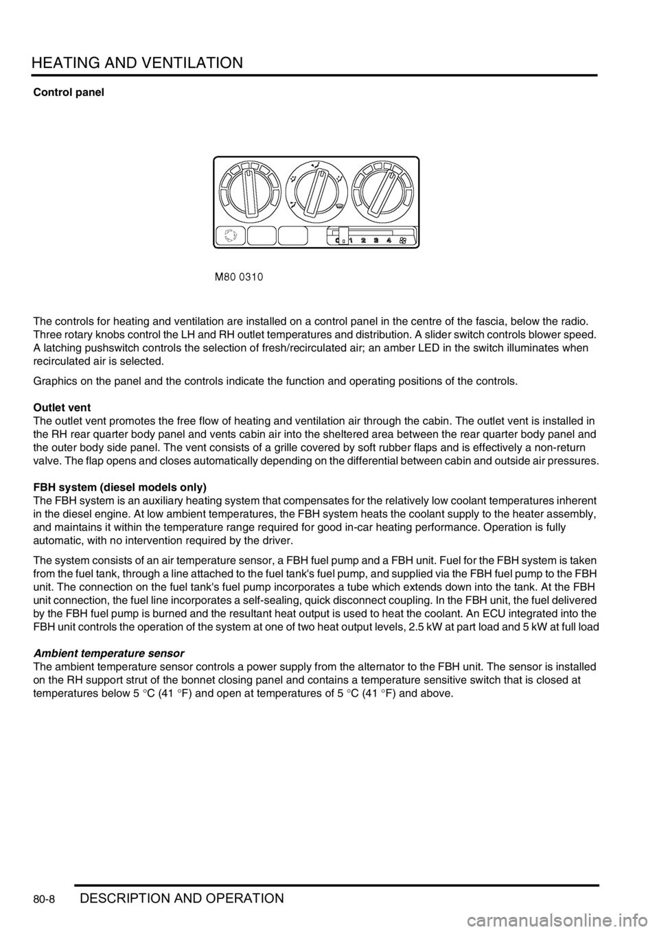
The controls for heating and ventilation are installed on a control panel in the centre of the fascia, below the radio.
Three rotary knobs control the LH and RH outlet temperatures and distribution. A slider switch controls blower speed.
A latching pushswitch controls the selection of fresh/recirculated air; an amber LED in the switch illuminates when
recirculated air is selected.
Graphics on the panel and the controls indicate the function and operating positions of the controls.
Outlet vent
The outlet vent promotes the free flow of heating and ventilation air through the cabin. The outlet vent is installed in
the RH rear quarter body panel and vents cabin air into the sheltered area between the rear quarter body panel and
the outer body side panel. The vent consists of a grille covered by soft rubber flaps and is effectively a non-return
valve. The flap opens and closes automatically depending on the differential between cabin and outside air pressures.
FBH system (diesel models only)
The FBH system is an auxiliary heating system that compensates for the relatively low coolant temperatures inherent
in the diesel engine. At low ambient temperatures, the FBH system heats the coolant supply to the heater assembly,
and maintains it within the temperature range required for good in-car heating performance. Operation is fully
automatic, with no intervention required by the driver.
The system consists of an air temperature sensor, a FBH fuel pump and a FBH unit. Fuel for the FBH system is taken
from the fuel tank, through a line attached to the fuel tank's fuel pump, and supplied via the FBH fuel pump to the FBH
unit. The connection on the fuel tank's fuel pump incorporates a tube which extends down into the tank. At the FBH
unit connection, the fuel line incorporates a self-sealing, quick disconnect coupling. In the FBH unit, the fuel delivered
by the FBH fuel pump is burned and the resultant heat output is used to heat the coolant. An ECU integrated into the
FBH unit controls the operation of the system at one of two heat output levels, 2.5 kW at part load and 5 kW at full load
Ambient temperature sensor
The ambient temperature sensor controls a power supply from the alternator to the FBH unit. The sensor is installed
on the RH support strut of the bonnet closing panel and contains a temperature sensitive switch that is closed at
temperatures below 5 °C (41 °F) and open at temperatures of 5 °C (41 °F) and above.
Page 1168 of 1529

HEATING AND VENTILATION
DESCRIPTION AND OPERATION 80-11
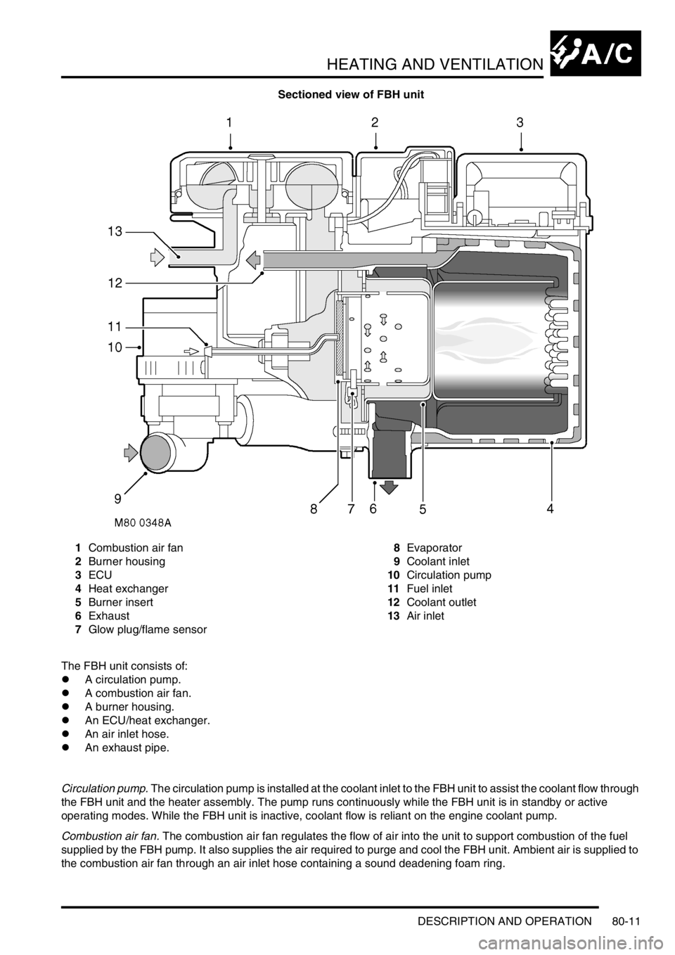
Sectioned view of FBH unit
1Combustion air fan
2Burner housing
3ECU
4Heat exchanger
5Burner insert
6Exhaust
7Glow plug/flame sensor8Evaporator
9Coolant inlet
10Circulation pump
11Fuel inlet
12Coolant outlet
13Air inlet
The FBH unit consists of:
lA circulation pump.
lA combustion air fan.
lA burner housing.
lAn ECU/heat exchanger.
lAn air inlet hose.
lAn exhaust pipe.
Circulation pump. The circulation pump is installed at the coolant inlet to the FBH unit to assist the coolant flow through
the FBH unit and the heater assembly. The pump runs continuously while the FBH unit is in standby or active
operating modes. While the FBH unit is inactive, coolant flow is reliant on the engine coolant pump.
Combustion air fan. The combustion air fan regulates the flow of air into the unit to support combustion of the fuel
supplied by the FBH pump. It also supplies the air required to purge and cool the FBH unit. Ambient air is supplied to
the combustion air fan through an air inlet hose containing a sound deadening foam ring.