sensor LAND ROVER DISCOVERY 1999 Workshop Manual
[x] Cancel search | Manufacturer: LAND ROVER, Model Year: 1999, Model line: DISCOVERY, Model: LAND ROVER DISCOVERY 1999Pages: 1529, PDF Size: 34.8 MB
Page 871 of 1529

BRAKES
70-18 DESCRIPTION AND OPERATION
The SLABS ECU continually calculates vehicle speed using the wheel speed inputs from all four ABS sensors. The
calculated vehicle speed is then used as a reference against which individual wheel speeds are monitored for
unacceptable acceleration or deceleration. The ABS sensor inputs are also used by the SLABS ECU to detect vehicle
deceleration rate, vehicle cornering rate and rough terrain.
The engaged forward gear and (on manual gearbox models) the clutch status are computed from the engine data
input, the engine speed input and vehicle speed. Reverse gear status is provided by an input from the reverse lamp
switch (manual gearbox models) or the BCU (automatic gearbox models). On automatic models, the BCU also
provides the neutral selected input.
In addition to controlling the brake related functions, the SLABS ECU:
lControls the operation of the self levelling suspension (SLS) system (where fitted).
+ REAR SUSPENSION, DESCRIPTION AND OPERATION, Description.
lOn V8 models, outputs a rough road signal to the ECM when traversing rough terrain.
lOutputs a vehicle speed signal.
The vehicle speed signal is output to the following systems (where fitted):
lActive Cornering Enhancement.
+ FRONT SUSPENSION, DESCRIPTION AND OPERATION, Description - ACE.
lAir conditioning.
+ AIR CONDITIONING, DESCRIPTION AND OPERATION, Description.
lCruise control.
+ ENGINE MANAGEMENT SYSTEM - Td5, DESCRIPTION AND OPERATION, Description.
+ ENGINE MANAGEMENT SYSTEM - V8, DESCRIPTION AND OPERATION, Description - engine
management.
lEngine management.
+ ENGINE MANAGEMENT SYSTEM - Td5, DESCRIPTION AND OPERATION, Description.
+ ENGINE MANAGEMENT SYSTEM - V8, DESCRIPTION AND OPERATION, Description - engine
management.
lIn-car entertainment.
+ IN CAR ENTERTAINMENT, DESCRIPTION AND OPERATION, Description.
lInstrument pack.
+ INSTRUMENTS, DESCRIPTION AND OPERATION, Description.
5 Front right inlet solenoid valve Output
6 Shuttle valve switches Input
7 Rear left outlet solenoid valve Output
8 Rear left inlet solenoid valve Output
9 Centre differential lock switch Input
10 Rear right outlet solenoid valve Output
11 Rear right inlet solenoid valve Output
12 Brake lamp relay Output
15 Return pump relay Output
C0655
7 Audible warning Output
10 Engine speed Input
Connector and pins not listed are either not used or used by the self levelling suspension system.
+ REAR SUSPENSION, DESCRIPTION AND OPERATION, Description.
Connector/Pin
No.Description Input/Output
Page 872 of 1529

BRAKES
DESCRIPTION AND OPERATION 70-19
ABS sensors
The ABS sensors supply the SLABS ECU with a sinusoidal speed signal from each wheel. An inductive sensor,
installed in the hub bearing of each wheel, senses off a 60 tooth exciter ring integrated into the inner race of the hub
bearing. Each ABS sensor has a fly-lead connecting it to the vehicle wiring.
HDC switch
The HDC switch is a latching push switch installed on the fascia, in the switchpack inboard of the steering wheel.
When pushed in, the switch connects an ignition supply to the SLABS ECU to initiate HDC.
Warning indications
The SLABS ECU operates audible and visual warnings to convey brake system status.
Audible warning
A repetitive chime, at a frequency of 2 Hz, draws attention to warning lamp indications. The chime is produced on the
speaker in the instrument pack.
Warning lamps
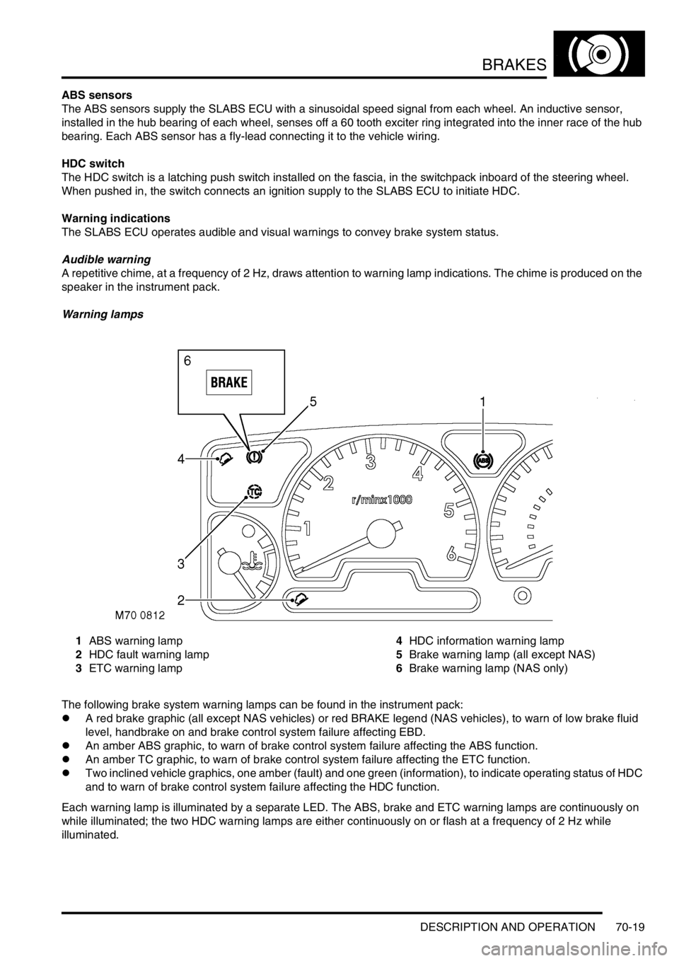
1ABS warning lamp
2HDC fault warning lamp
3ETC warning lamp4HDC information warning lamp
5Brake warning lamp (all except NAS)
6Brake warning lamp (NAS only)
The following brake system warning lamps can be found in the instrument pack:
lA red brake graphic (all except NAS vehicles) or red BRAKE legend (NAS vehicles), to warn of low brake fluid
level, handbrake on and brake control system failure affecting EBD.
lAn amber ABS graphic, to warn of brake control system failure affecting the ABS function.
lAn amber TC graphic, to warn of brake control system failure affecting the ETC function.
lTwo inclined vehicle graphics, one amber (fault) and one green (information), to indicate operating status of HDC
and to warn of brake control system failure affecting the HDC function.
Each warning lamp is illuminated by a separate LED. The ABS, brake and ETC warning lamps are continuously on
while illuminated; the two HDC warning lamps are either continuously on or flash at a frequency of 2 Hz while
illuminated.
Page 876 of 1529

BRAKES
DESCRIPTION AND OPERATION 70-23
Typical disabled times
Diagnostics
While the ignition is on, the diagnostics function of the SLABS ECU monitors the system for faults. In addition, the
return pump is tested by pulsing it briefly immediately after the engine starts provided vehicle speed exceeded 4.4
mph (7 km/h) during the previous ignition cycle. If a fault exists in a warning lamp circuit, the lamp will not illuminate
during the lamp check at ignition on but, provided there are no other faults, the related function will otherwise be fully
operational. If a fault is detected during the power up, the SLABS ECU stores a related fault code in memory and
illuminates the appropriate fault warning lamps. If a fault is detected later in the drive cycle, the SLABS ECU also
sounds the audible warning three times.
Fault codes and diagnostic routines can be accessed by connecting Testbook to the vehicle's diagnostic connector
in the driver's footwell.
Warning lamp fault operation
After detecting a fault, the SLABS ECU selects an appropriate default strategy which, where possible, retains some
operational capability. A shuttle valve switch fault and throttle position signal fault are classified as permanent faults.
If a permanent fault is detected, the related warning lamp illumination and default strategies are automatically
employed in subsequent ignition cycles, even if the fault is intermittent, until the fault has been rectified and cleared
from memory. If a non permanent fault is detected, the related warning lamp illumination and default strategies will
only be employed in subsequent ignition cycles if the fault is still present.
After rectification of an ABS sensor fault, the ABS and ETC functions are disabled, and the ABS warning lamp remains
illuminated after the lamp check, until vehicle speed exceeds 9.4 mph (15 km/h) (to allow additional checks to be
performed).
Vehicle speed, mph (km/h) Time, minutes
1.3 (2) 40
12.5 (20) 33
15.6 (25) 17
25.0 (40) 9
31.3 (50) 6
Item Check Warning lamp
ABS Brake ETC HDC
fault
ABS sensors Resistance (to check status) On On On On
Brake lamps relay Open/Short circuit Off Off Off On
Engine data Sticking throttle, signal failure, data corruption Off Off On On
Inlet solenoid valves Open/Short circuit On On On On
Outlet solenoid valves Open/Short circuit On On On On
Reference earth Connection to earth On On On On
Return pump monitor Correct pump operation On On On On
Return pump relay Open/Short circuit On On On On
Shuttle valve switches Open/Short circuit On On On On
SLABS ECU Internal failure On On On On
Supply voltages Range (10 to 16 V) On On On On
Page 877 of 1529

BRAKES
70-24 DESCRIPTION AND OPERATION
Default strategies
Electrical data
Nominal resistance values for applicable brake control components are as detailed below:
Fault Default strategy
Brake lamps relay ABS: Enabled.
ETC: Enabled.
EBD: Enabled.
HDC: Enabled.
Throttle position signal failure ABS: Enabled.
ETC: Disabled.
EBD: Enabled.
HDC: Immediately disabled if not in active braking mode; faded out then disabled if in active
braking mode.
No reference earth ABS: Disabled.
ETC: Disabled.
EBD: Partly disabled.
HDC: Disabled.
Return pump or relay fault ABS: Disabled.
ETC: Disabled.
EBD: Partly disabled.
HDC: Disabled.
Shuttle valve switch failure ABS: Deceleration threshold increased; return pump activated if sum of output valve
actuation on one axle exceeds 140 milliseconds.
ETC: Disabled.
EBD: Inlet valves of rear axle close at vehicle deceleration rates of 0.3 g and above.
HDC: Disabled.
SLABS ECU internal failure ABS: Disabled.
ETC: Disabled.
EBD: Disabled.
HDC: Disabled.
Supply voltage out of limits ABS: Disabled.
ETC: Disabled.
EBD: Disabled.
HDC: Disabled.
Component Resistance, ohms
Brake lamp relay coil117 - 143
Return pump relay coil82.8 - 101.2
ABS sensor950 - 1100
Shuttle valve switches, both open (brakes off) 2977 - 3067
Shuttle valve switches, both closed (brakes on) 1007 - 1037
Shuttle valve switches, one open, one closed 1992 - 2052
Inlet solenoid valve5.9 - 7.3
Outlet solenoid valve3.0 - 3.6
Page 901 of 1529

BRAKES
70-48 REPAIRS
Sensor – ABS – front
$% 70.65.30
ABS sensor is supplied fitted to wheel hub and
must not be removed.
Remove
1.Remove wheel hub.
+ FRONT SUSPENSION, REPAIRS,
Wheel hub.
Refit
1.Fit wheel hub.
+ FRONT SUSPENSION, REPAIRS,
Wheel hub.
Sensor – ABS – rear
$% 70.65.31
ABS sensor is supplied fitted to wheel hub and
must not be removed.
Remove
1.Remove wheel hub.
+ REAR SUSPENSION, REPAIRS,
Wheel hub.
Refit
1.Fit wheel hub.
+ REAR SUSPENSION, REPAIRS,
Wheel hub.
Page 906 of 1529

RESTRAINT SYSTEMS
DESCRIPTION AND OPERATION 75-3
Description - SRS
General
The purpose of the Supplementary Restraint System (SRS) is to reduce the impact of the driver and passenger
against the vehicle's interior in the event of a serious accident.
The SRS system is a stand-alone system. There are no remotely mounted crash sensors. The only external input to
the DCU is power. The system only becomes live when the ignition is switched on.
The SRS consists of the following components:
lDiagnostic and control unit (DCU).
lSRS warning lamp.
lRotary coupler.
lDriver airbag module.
lDriver seat belt pretensioner.
lPassenger airbag module.
lPassenger seat belt pretensioner.
The passenger airbag is optional in some markets. All other components are standard fit in all markets. The SRS
functions the same in all markets.
Page 911 of 1529

RESTRAINT SYSTEMS
75-8 DESCRIPTION AND OPERATION
Diagnostic and Control Unit (DCU)
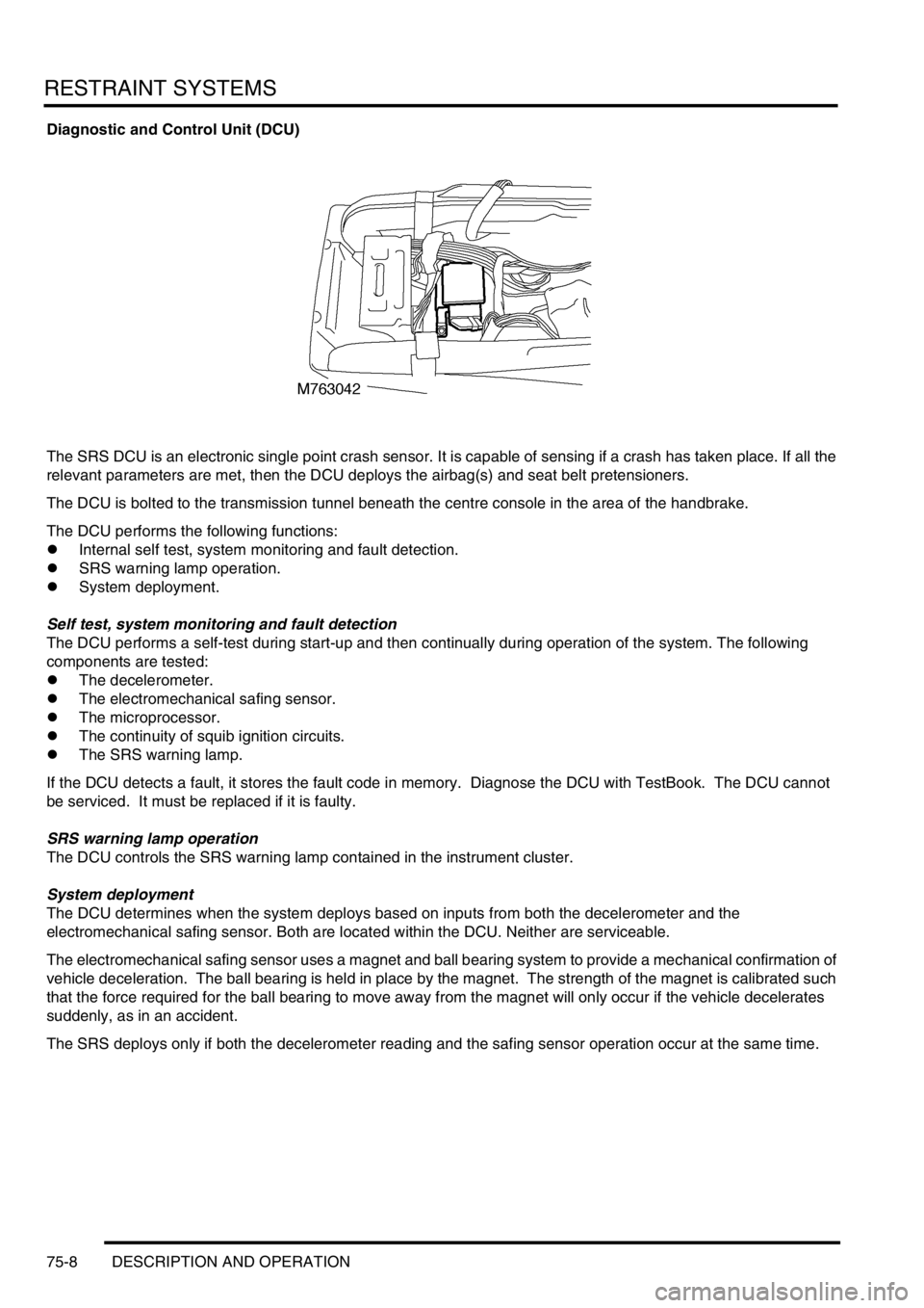
The SRS DCU is an electronic single point crash sensor. It is capable of sensing if a crash has taken place. If all the
relevant parameters are met, then the DCU deploys the airbag(s) and seat belt pretensioners.
The DCU is bolted to the transmission tunnel beneath the centre console in the area of the handbrake.
The DCU performs the following functions:
lInternal self test, system monitoring and fault detection.
lSRS warning lamp operation.
lSystem deployment.
Self test, system monitoring and fault detection
The DCU performs a self-test during start-up and then continually during operation of the system. The following
components are tested:
lThe decelerometer.
lThe electromechanical safing sensor.
lThe microprocessor.
lThe continuity of squib ignition circuits.
lThe SRS warning lamp.
If the DCU detects a fault, it stores the fault code in memory. Diagnose the DCU with TestBook. The DCU cannot
be serviced. It must be replaced if it is faulty.
SRS warning lamp operation
The DCU controls the SRS warning lamp contained in the instrument cluster.
System deployment
The DCU determines when the system deploys based on inputs from both the decelerometer and the
electromechanical safing sensor. Both are located within the DCU. Neither are serviceable.
The electromechanical safing sensor uses a magnet and ball bearing system to provide a mechanical confirmation of
vehicle deceleration. The ball bearing is held in place by the magnet. The strength of the magnet is calibrated such
that the force required for the ball bearing to move away from the magnet will only occur if the vehicle decelerates
suddenly, as in an accident.
The SRS deploys only if both the decelerometer reading and the safing sensor operation occur at the same time.
Page 912 of 1529

RESTRAINT SYSTEMS
DESCRIPTION AND OPERATION 75-9
Operation - SRS
The diagnostic and control unit (DCU) controls the SRS system. The DCU is located beneath the centre console close
to the handbrake area. The DCU contains both an electronic deceleration sensor as well as an electromechanical
safing sensor. When the electronic deceleration sensor within the DCU detects rapid deceleration of the vehicle, it
compares the deceleration rate with stored values in its' memory. If the deceleration rate exceeds the stored value
and the electromechanical safing sensor triggers, the DCU deploys the airbag and the seat belt pretensioners. The
DCU will not deploy the airbags and seat belt pretensioners unless both sensors trigger.
The SRS has diagnostic capabilities through TestBook. In the event that a fault is detected, the DCU alerts the driver
by illuminating a warning lamp in the instrument cluster.
The DCU controls the following:
lSRS warning lamp.
lDrivers airbag module.
lPassenger airbag module (where fitted).
lDriver seat belt pretensioner.
lPassenger seat belt pretensioner.
WARNING: The integrity of the SRS system are critical for safety reasons. Ensure the following precautions
are always adhered to:
lNever install used SRS components from another vehicle or attempt to repair an SRS component.
lWhen repairing an SRS system only use genuine new parts.
lNever apply electrical power to an SRS component unless instructed to do so as part of an approved test
procedure.
lSpecial Torx bolts are necessary for installing the airbag module - do not use other bolts. Ensure bolts
are tightened to the correct torque.
lAlways use new fixings when replacing an SRS component.
lEnsure the SRS Diagnostic Control Unit (DCU) is always installed correctly. There must not be any gap
between the DCU and the bracket to which it is mounted. An incorrectly mounted DCU could cause the
system to malfunction.
System deployment
The airbag and seat belt pretensioners deploy to protect the front seat occupants when the DCU senses a rapid
vehicle deceleration. The system deploys when the following conditions are met:
lThe ignition switch is on.
lThe vehicle decelerates beyond a threshold defined within the DCU.
lThe electromechanical safing sensor within the DCU triggers.
When all of the above conditions are met, the DCU deploys the airbag(s) and seat belt pretensioners. If the above
conditions are not met, the DCU will not deploy the system.
Component replacement policy
After an impact which deploys the airbags and pretensioners, the following components must be renewed:
lDCU.
lDriver and passenger airbag modules.
lDriver and passenger buckle pretensioners.
lRotary coupler.
lFlyleads (where applicable) connecting airbags and pre-tensioners to SRS harness
SRS warning lamp
The SRS warning lamp illuminates for 5 seconds during system readiness check on starting the engine. The SRS
warning lamp extinguishes for one second after the system readiness check is performed. If a fault is present the
warning lamp then illuminates continuously. If no fault is present, the SRS warning lamp remains extinguished. If a
system fault occurs in excess of two seconds after the readiness check has been completed, the SRS warning lamp
illuminates for that ignition cycle. It remains illuminated for a minimum of 12 seconds ± 4 seconds for all fault
conditions.
The SRS warning lamp will only illuminate for low voltage concerns while the low voltage condition is present. If the
low voltage condition is corrected, the SRS warning lamp extinguishes and the fault is recorded in the DCU's memory.
Page 914 of 1529

RESTRAINT SYSTEMS
DESCRIPTION AND OPERATION 75-11
DESCRIPTION AND OPERAT ION
Description - seat belts
An inertia reel, three point seat belt is installed at each seat position. The inertia reels incorporate a liftshaft locking
system with webbing sensor and car sensor activating mechanisms. The webbing sensor activates the locking system
if the webbing is subjected to a sharp pull. The car sensor activates the locking system if the vehicle is subjected to
sudden deceleration or a severe tilt angle.
Front seat belts
The inertia reel of each front seat belt is attached to the related B/C post, behind the finishers. The webbing runs from
the inertia reel, through a height adjuster, to an anchor point at the base of the B/C post. The buckle assembly for
each belt is attached to the inboard side of the seat and contains the SRS pretensioner.
Rear seat belts
The inertia reels for the outboard rear seats are attached to the body behind the loadspace side trim casings. The
webbing runs from each inertia reel through an upper mounting, suspended from the cantrail, to an anchor point on
the rear wheel arch.
The inertia reel of the centre rear seat is mounted in the back of the seat. The webbing runs through a guide on the
top of the seat and is anchored to one of the seat hinge points. The buckles for the rear seat belts are also attached
to the seat hinge points.
Third row seat belts
The inertia reel of each third row rear seat belt is attached to the related E post, behind the loadspace side trim
casing.The webbing runs from the inertia reel, through an upper mounting on the E post to an anchor point on the
loadspace floor. The buckle is mounted on the inboard side of the seat.
Page 961 of 1529

EXTERIOR FITTINGS
76-2-14 REPAIRS
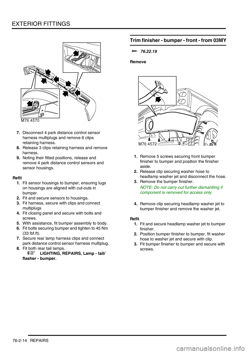
7.Disconnect 4 park distance control sensor
harness multiplugs and remove 6 clips
retaining harness.
8.Release 3 clips retaining harness and remove
harness.
9.Noting their fitted positions, release and
remove 4 park distance control sensors and
sensor housings.
Refit
1.Fit sensor housings to bumper, ensuring lugs
on housings are aligned with cut-outs in
bumper.
2.Fit and secure sensors to housings.
3.Fit harness, secure with clips and connect
multiplugs
4.Fit closing panel and secure with bolts and
screws.
5.With assistance, fit bumper assembly to body.
6.Fit bolts securing bumper and tighten to 45 Nm
(33 lbf.ft).
7.Secure rear lamp harness clips and connect
park distance control sensor harness multiplug.
8.Fit both rear tail lamps.
+ LIGHTING, REPAIRS, Lamp - tail/
flasher - bumper.
Trim finisher - bumper - front - from 03MY
$% 76.22.19
Remove
1.Remove 5 screws securing front bumper
finisher to bumper and position the finisher
aside.
2.Release clip securing washer hose to
headlamp washer jet and disconnect the hose.
3.Remove the bumper finisher.
NOTE: Do not carry out further dismantling if
component is removed for access only.
4.Remove clip securing headlamp washer jet to
bumper finisher and remove the washer jet.
Refit
1.Fit and secure headlamp washer jet to bumper
finisher.
2.Position bumper finisher to bumper, fit washer
hose to washer jet and secure with clip.
3.Fit bumper finisher to bumper and secure with
screws.