sensor LAND ROVER DISCOVERY 1999 Owner's Guide
[x] Cancel search | Manufacturer: LAND ROVER, Model Year: 1999, Model line: DISCOVERY, Model: LAND ROVER DISCOVERY 1999Pages: 1529, PDF Size: 34.8 MB
Page 191 of 1529

ENGINE - V8
12-2-36 REPAIRS
Pump - oil
$% 12.60.26
Remove
1.Remove timing gear cover gasket.
+ ENGINE - V8, REPAIRS, Gasket -
timing gear cover.
2.Remove bolt securing CMP sensor, remove
clamp and sensor.
3.Remove 6 bolts securing coolant pump,
remove pump and discard gasket.
4.Remove oil pressure switch and discard
sealing washer.
5.Remove 4 bolts securing oil filter head, remove
filter head and discard 2 'O' rings.
6.Remove filter head adaptor. Refit
1.Ensure filter head adaptor is clean.
2.Fit filter head adaptor and tighten bolts to 13
Nm (9 lbf.ft).
3.Clean filter head and mating face.
4.Fit new 'O' rings to filter head and filter head
adaptor.
5.Fit filter head and tighten bolts to 8 Nm (6 lbf.ft).
6.Ensure oil pressure switch and mating face is
clean.
7.Fit new sealing washer and tighten switch to 15
Nm (11 lbf.ft).
8.Clean coolant pump and mating face.
9.Use a new gasket and fit coolant pump.
Tighten bolts securing coolant pump to 25 Nm
(19 lbf.ft).
10.Ensure CMP sensor is clean and fit sensor to
cover.
11.Fit clamp to CMP sensor and tighten bolt to 8
Nm (6 lbf.ft).
12.Fit timing gear cover gasket.
+ ENGINE - V8, REPAIRS, Gasket -
timing gear cover.
Page 196 of 1529

ENGINE - V8
REPAIRS 12-2-41
Gasket - timing gear cover
$% 12.65.04
Remove
1.Remove oil pick-up strainer.
+ ENGINE - V8, REPAIRS, Strainer -
oil pick-up.
2.Remove timing gear cover oil seal.
+ ENGINE - V8, REPAIRS, Seal - cover
- timing gears.
3.Remove engine oil filter.
+ ENGINE - V8, REPAIRS, Filter - oil.
4.Remove and discard 3 bolts securing coolant
pump pulley and remove pulley.
5.Remove 3 bolts securing PAS pump pulley and
remove pulley.
6.Drain cooling system.
+ COOLING SYSTEM - V8,
ADJUSTMENTS, Drain and refill.7.Release clip and disconnect coolant hose from
coolant pump.
8.Disconnect multiplug from oil pressure switch.
9.Disconnect multiplug from CMP sensor.
10. If fitted: Loosen union and disconnect oil
cooler pipe from timing gear cover. Remove
and discard 'O' ring.
CAUTION: Always fit plugs to open
connections to prevent contamination.
11.Remove 9 bolts securing timing gear cover and
remove cover. Remove and discard gasket.
Page 197 of 1529

ENGINE - V8
12-2-42 REPAIRS
Refit
1.Clean mating faces of timing gear cover and
cylinder block. Clean dowels and dowel holes.
Ensure bolt holes are clean and dry, remove all
traces of sealant from bolt threads.
2.Fit new gasket, dry, to dowels in cylinder block.
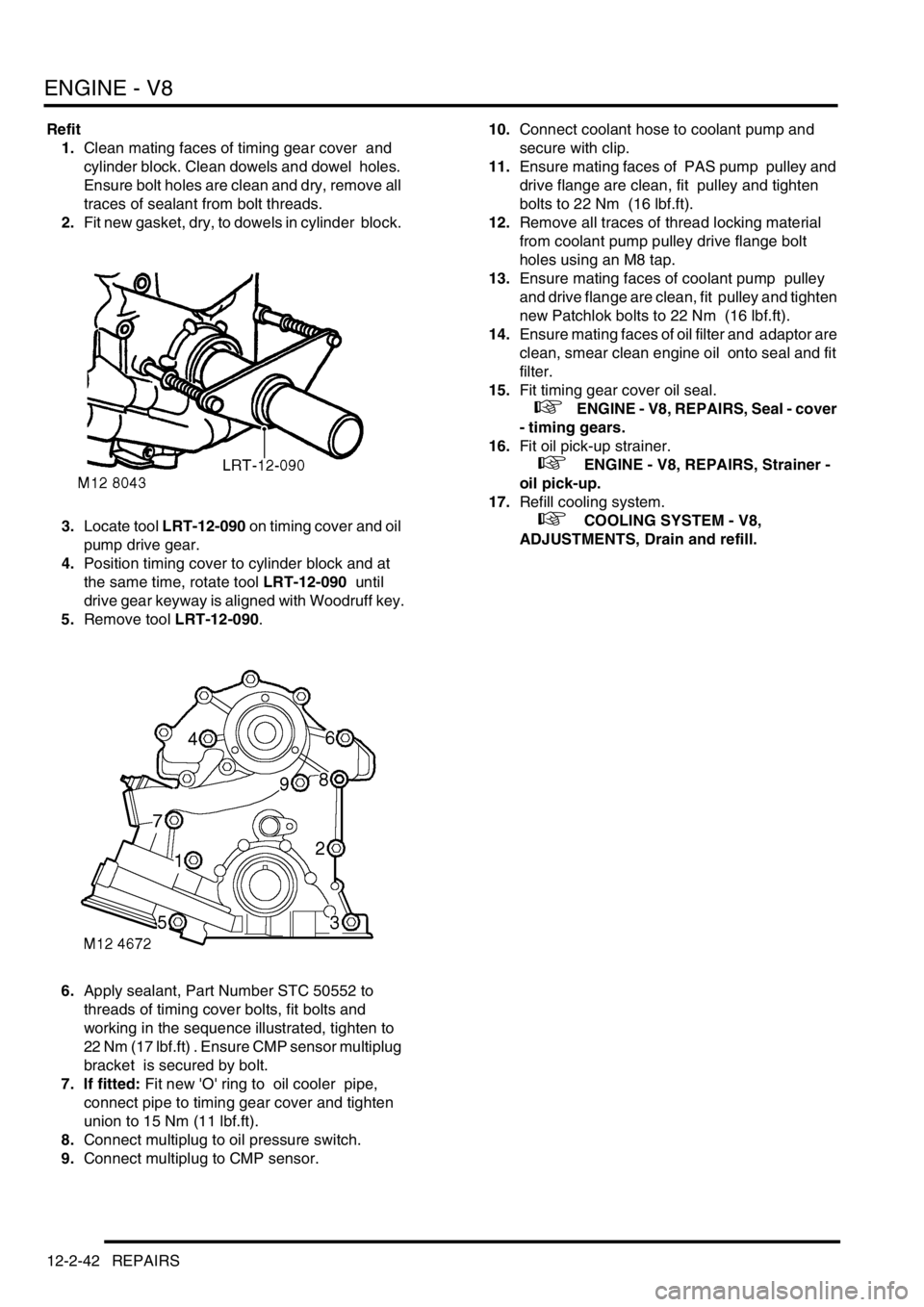
3.Locate tool LRT-12-090 on timing cover and oil
pump drive gear.
4.Position timing cover to cylinder block and at
the same time, rotate tool LRT-12-090 until
drive gear keyway is aligned with Woodruff key.
5.Remove tool LRT-12-090.
6.Apply sealant, Part Number STC 50552 to
threads of timing cover bolts, fit bolts and
working in the sequence illustrated, tighten to
22 Nm (17 lbf.ft) . Ensure CMP sensor multiplug
bracket is secured by bolt.
7. If fitted: Fit new 'O' ring to oil cooler pipe,
connect pipe to timing gear cover and tighten
union to 15 Nm (11 lbf.ft).
8.Connect multiplug to oil pressure switch.
9.Connect multiplug to CMP sensor. 10.Connect coolant hose to coolant pump and
secure with clip.
11.Ensure mating faces of PAS pump pulley and
drive flange are clean, fit pulley and tighten
bolts to 22 Nm (16 lbf.ft).
12.Remove all traces of thread locking material
from coolant pump pulley drive flange bolt
holes using an M8 tap.
13.Ensure mating faces of coolant pump pulley
and drive flange are clean, fit pulley and tighten
new Patchlok bolts to 22 Nm (16 lbf.ft).
14.Ensure mating faces of oil filter and adaptor are
clean, smear clean engine oil onto seal and fit
filter.
15.Fit timing gear cover oil seal.
+ ENGINE - V8, REPAIRS, Seal - cover
- timing gears.
16.Fit oil pick-up strainer.
+ ENGINE - V8, REPAIRS, Strainer -
oil pick-up.
17.Refill cooling system.
+ COOLING SYSTEM - V8,
ADJUSTMENTS, Drain and refill.
Page 204 of 1529

ENGINE - V8
OVERHAUL 12-2-49
Seal - crankshaft - rear - automatic
models
$% 12.21.20.01
Disassembly
1.Remove CKP sensor.
+ ENGINE MANAGEMENT SYSTEM -
V8, REPAIRS, Sensor - crankshaft position
(CKP).
Note: Later engines are fitted with a modified
starter ring gear which incorporates the reluctor
plate, spacer and hub. The modified ring gear
may be fitted as a replacement to early
engines.
2. Early engines: Remove 4 bolts securing drive
plate clamp ring and remove ring.
3. Early engines: Remove drive plate from hub.
4. Early engines: Remove 6 Allen bolts securing
hub and starter ring gear, remove hub, starter
ring gear and collect spacer.
Note: On early engines, balance weights are on
engine side of drive plate, replacement drive
plates will have balance weights on torque
converter side of drive plate.5. Later engines: Remove 4 bolts securing drive
plate clamp ring and remove ring.
6. Later engines: Remove drive plate.
7. Later engines: Remove 6 Allen bolts securing
starter ring gear to crankshaft, remove starter
ring gear.
8.Carefully remove oil seal from cylinder block to
avoid damage to seal location or running
surface on crankshaft.
Page 205 of 1529

ENGINE - V8
12-2-50 OVERHAUL
Reassembly
1.Ensure both seal location and running surface
on crankshaft are clean. Ensure that bolt holes
in crankshaft are clean and dry.
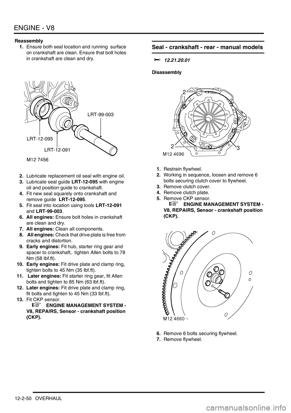
2.Lubricate replacement oil seal with engine oil.
3.Lubricate seal guide LRT-12-095 with engine
oil and position guide to crankshaft.
4.Fit new seal squarely onto crankshaft and
remove guide LRT-12-095.
5.Fit seal into location using tools LRT-12-091
and LRT-99-003.
6. All engines: Ensure bolt holes in crankshaft
are clean and dry.
7. All engines: Clean all components.
8. All engines: Check that drive plate is free from
cracks and distortion.
9. Early engines: Fit hub, starter ring gear and
spacer to crankshaft, tighten Allen bolts to 78
Nm (58 lbf.ft).
10. Early engines: Fit drive plate and clamp ring,
tighten bolts to 45 Nm (35 lbf.ft).
11. Later engines: Fit starter ring gear, fit Allen
bolts and tighten to 85 Nm (63 lbf.ft).
12. Later engines: Fit drive plate and clamp ring,
fit bolts and tighten to 45 Nm (33 lbf.ft).
13.Fit CKP sensor.
+ ENGINE MANAGEMENT SYSTEM -
V8, REPAIRS, Sensor - crankshaft position
(CKP).
Seal - crankshaft - rear - manual models
$% 12.21.20.01
Disassembly
1.Restrain flywheel.
2.Working in sequence, loosen and remove 6
bolts securing clutch cover to flywheel.
3.Remove clutch cover.
4.Remove clutch plate.
5.Remove CKP sensor.
+ ENGINE MANAGEMENT SYSTEM -
V8, REPAIRS, Sensor - crankshaft position
(CKP).
6.Remove 6 bolts securing flywheel.
7.Remove flywheel.
Page 206 of 1529

ENGINE - V8
OVERHAUL 12-2-51
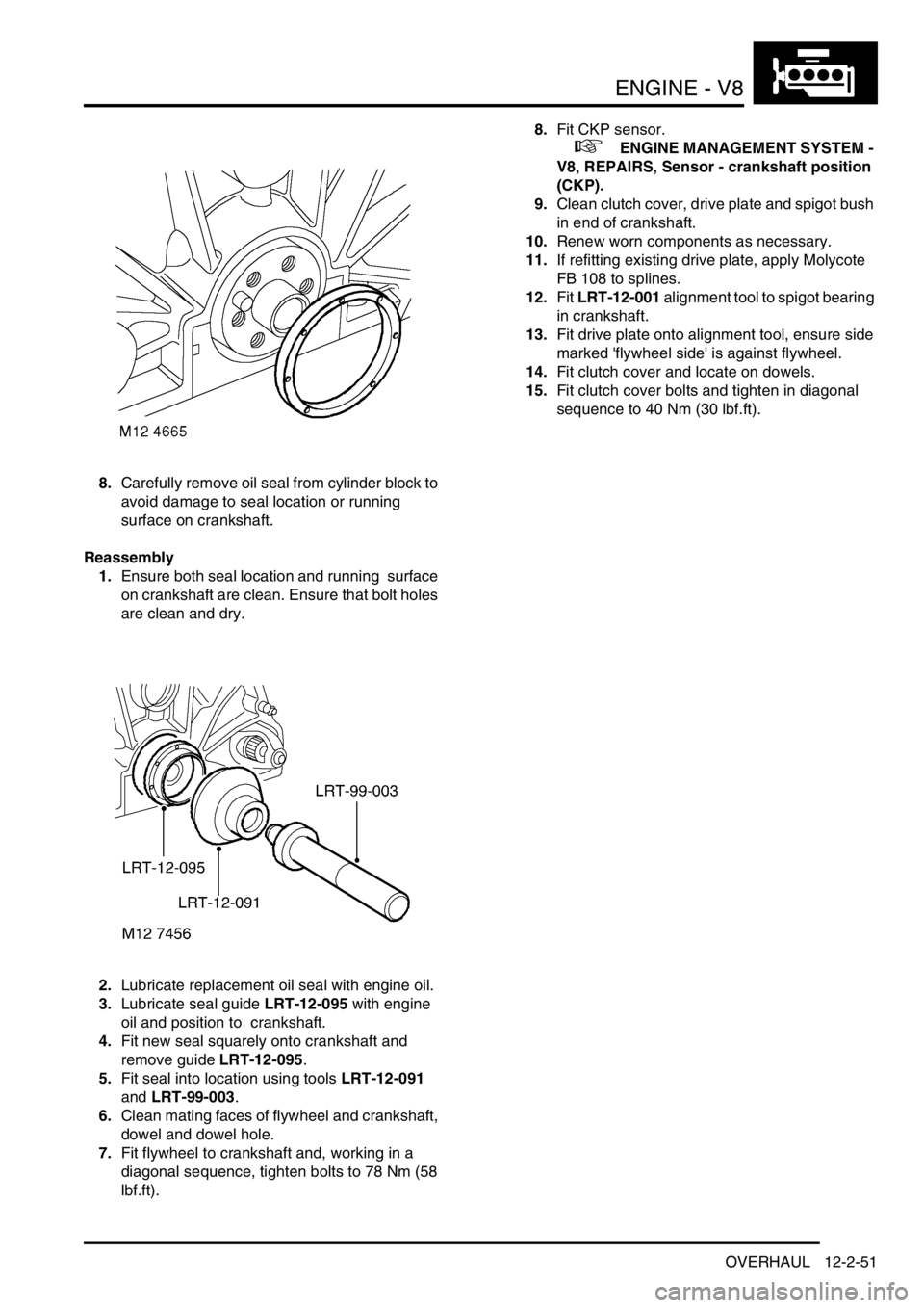
8.Carefully remove oil seal from cylinder block to
avoid damage to seal location or running
surface on crankshaft.
Reassembly
1.Ensure both seal location and running surface
on crankshaft are clean. Ensure that bolt holes
are clean and dry.
2.Lubricate replacement oil seal with engine oil.
3.Lubricate seal guide LRT-12-095 with engine
oil and position to crankshaft.
4.Fit new seal squarely onto crankshaft and
remove guide LRT-12-095.
5.Fit seal into location using tools LRT-12-091
and LRT-99-003.
6.Clean mating faces of flywheel and crankshaft,
dowel and dowel hole.
7.Fit flywheel to crankshaft and, working in a
diagonal sequence, tighten bolts to 78 Nm (58
lbf.ft). 8.Fit CKP sensor.
+ ENGINE MANAGEMENT SYSTEM -
V8, REPAIRS, Sensor - crankshaft position
(CKP).
9.Clean clutch cover, drive plate and spigot bush
in end of crankshaft.
10.Renew worn components as necessary.
11.If refitting existing drive plate, apply Molycote
FB 108 to splines.
12.Fit LRT-12-001 alignment tool to spigot bearing
in crankshaft.
13.Fit drive plate onto alignment tool, ensure side
marked 'flywheel side' is against flywheel.
14.Fit clutch cover and locate on dowels.
15.Fit clutch cover bolts and tighten in diagonal
sequence to 40 Nm (30 lbf.ft).
Page 212 of 1529

ENGINE - V8
OVERHAUL 12-2-57
Reassembly
1.Clean timing gear cover and mating face.
2.Clean oil seal register in timing gear cover.
3.Ensure bolt holes in cylinder block are clean
and dry, remove all traces of sealant from
threads of timing cover bolts.
4.Fit a new timing gear cover gasket, dry, to
timing cover locating dowels.
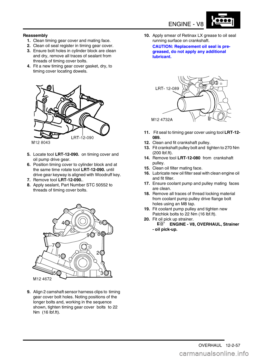
5.Locate tool LRT-12-090. on timing cover and
oil pump drive gear.
6.Position timing cover to cylinder block and at
the same time rotate tool LRT-12-090. until
drive gear keyway is aligned with Woodruff key.
7.Remove tool LRT-12-090..
8.Apply sealant, Part Number STC 50552 to
threads of timing cover bolts.
9.Align 2 camshaft sensor harness clips to timing
gear cover bolt holes. Noting positions of the
longer bolts and, working in the sequence
shown, tighten timing gear cover bolts to 22
Nm (16 lbf.ft). 10.Apply smear of Retinax LX grease to oil seal
running surface on crankshaft.
CAUTION: Replacement oil seal is pre-
greased, do not apply any additional
lubricant.
11. Fit seal to timing gear cover using tool LRT-12-
089.
12.Clean and fit crankshaft pulley.
13.Fit crankshaft pulley bolt and tighten to 270 Nm
(200 lbf.ft).
14.Remove tool LRT-12-080 from crankshaft
pulley.
15.Clean oil filter mating face.
16.Lubricate new oil filter seal with clean engine oil
and fit filter.
17.Ensure coolant pump and pulley mating faces
are clean.
18.Remove all traces of thread locking material
from coolant pump pulley drive flange bolt
holes using an M8 tap.
19.Fit coolant pump pulley and tighten new
Patchlok bolts to 22 Nm (16 lbf.ft).
20.Fit oil pick up strainer.
+ ENGINE - V8, OVERHAUL, Strainer
- oil pick-up.
Page 235 of 1529

EMISSION CONTROL - V8
17-2-2 DESCRIPTION AND OPERATION
Exhaust emission control
1RH catalytic converter
2Heated oxygen sensors – post-catalytic
converter (2 off – NAS only)3LH catalytic converter
4Heated oxygen sensors – pre-catalytic
converter (2 off)
Page 236 of 1529

EMISSION CONTROL - V8
DESCRIPTION AND OPERATION 17-2-3
Evaporative emission system
component layout
1Purge valve
2Service port
3Snorkel tube (UK / ROW only)
4CVS unit (NAS vehicles with vacuum type leak
detection only)
5EVAP canister breather tube
6Vent pipe – fuel tank to EVAP canister
7Relief valve regulated flow
8Relief valve (UK / ROW only)
9Relief valve free flow
10Fuel filler cap
11Liquid vapour separator #
(UK / ROW type shown)12Fuel filler hose (UK / ROW type shown)
13Tank breather hose (UK / ROW only)
14Vent hose
15Roll over valves (ROV's) –
(4 off, UK / ROW spec. shown)
16Fuel tank and breather assembly
17EVAP canister
18Purge line connection to engine manifold
19Tank EVAP system pressure sensor (NAS
vehicles with vacuum type leak detection only)
M17 0209
4
3
1
6
5
16
10
8
13
17
9
7
11
12
15
14
18
2
19
Page 238 of 1529

EMISSION CONTROL - V8
DESCRIPTION AND OPERATION 17-2-5
Evaporative emission system control
diagram
1Battery
2Fuse 13 (engine compartment fusebox)
3Inertia switch
4Main relay (engine compartment fusebox)
5Engine Control Module (ECM)
6Purge Valve (black harness connector)
7Canister vent solenoid (CVS) valve – NAS
vehicles with vacuum type EVAP system leak
detection capability only8Leak detection pump – NAS vehicles with
positive pressure type EVAP system leak
detection capability only
9Fuel tank pressure sensor – NAS vehicles with
vacuum type EVAP system leak detection
capability only
10Instrument pack (MIL warning light)
M17 0210
12
3
4
5
6
7
9
8
10