heater LAND ROVER DISCOVERY 1999 Repair Manual
[x] Cancel search | Manufacturer: LAND ROVER, Model Year: 1999, Model line: DISCOVERY, Model: LAND ROVER DISCOVERY 1999Pages: 1529, PDF Size: 34.8 MB
Page 1170 of 1529

HEATING AND VENTILATION
DESCRIPTION AND OPERATION 80-13
Operation
Air distribution
Turning the distribution knob on the control panel turns the control flaps in the heater assembly to direct air to the
corresponding fascia and footwell outlets.
Air temperature
Turning the LH or RH temperature knob on the control panel turns the related blend flaps in the heater assembly. The
blend flaps vary the proportion of air going through the cold air bypass and the heater matrix. The proportion varies,
between full bypass no heat and no bypass full heat, to correspond with the position of the temperature knob.
Blower speed
The blower can be selected off or to run at one of four speeds. While the ignition is on, when the blower switch is set
to positions 1, 2, 3, or 4, ignition power energises the blower relay, which supplies battery power to the blower. At
switch positions 1, 2 and 3, the blower switch also connects the blower to different earth paths through the resistor
pack, to produce corresponding differences of blower operating voltage and speed. At position 4, the blower switch
connects an earth direct to the blower, bypassing the resistor pack, and full battery voltage drives the blower at
maximum speed.
Fresh/Recirculated inlet air
When the recirculated air switch is latched in, the amber indicator LED in the switch illuminates and an earth is
connected to the recirculated air side of the fresh/recirculated air servo motor. The fresh/recirculated air servo motor
then turns the control flaps in the air inlet duct to close the fresh air inlet and open the recirculated air inlets.
When the latch of the recirculated air switch is released, the amber indicator LED in the switch extinguishes and the
earth is switched from the recirculated air side to the fresh air side of the fresh/recirculated air servo motor. The fresh/
recirculated air servo motor then turns the control flaps in the air inlet duct to open the fresh air inlet and close the
recirculated air inlets.
FBH system (where fitted)
The FBH system operates only while the engine is running and the ambient temperature is less than 5 °C (41 °F).
With the engine running and the ambient temperature below 5 °C (41 °F), the air temperature sensor connects the
alternator power supply to the ECU in the FBH unit. On receipt of the alternator power supply, the ECU starts the
circulation pump and, depending on the input from the temperature sensor in the heat exchanger, enters either a
standby or active mode of operation. If the heat exchanger casing temperature is 65 °C (149 °F) or above, the ECU
enters a standby mode of operation. If the heat exchanger casing temperature is below 65 °C (149 °F), the ECU enters
an active mode of operation. In the standby mode, the ECU monitors the heat exchanger casing temperature and
enters the active mode if it drops below 65 °C (149 °F). In the active mode, the ECU initiates a start sequence and
then operates the system at full or part load combustion to provide the required heat input to the coolant.
Start sequence
At the beginning of the start sequence the ECU energises the glow plug function of the glow plug/flame sensor, to
preheat the combustion chamber, and starts the combustion air fan at slow speed. After 30 seconds, the ECU
energises the FBH fuel pump at the starting sequence speed. The fuel delivered by the FBH fuel pump evaporates in
the combustion chamber, mixes with air from the combustion air fan and is ignited by the glow plug/flame sensor. The
ECU then progressively increases the speed of the FBH fuel pump and the combustion air fan to either part or full
load speed, as required by the system. Once full or part load speed is achieved, the ECU switches the glow plug/flame
sensor from the glow plug function to the flame sensing function to monitor combustion. From the beginning of the
start sequence to stable combustion takes approximately 90 seconds for a start to part load combustion and 150
seconds for a start to full load combustion.
Page 1172 of 1529
HEATING AND VENTILATION
REPAIRS 80-15
REPAIRS
Heater control and fan switch
$% 80.10.02
Remove
1.Remove louvre panel assembly.
+ INTERIOR TRIM COMPONENTS,
REPAIRS, Louvre panel assembly - centre
fascia.
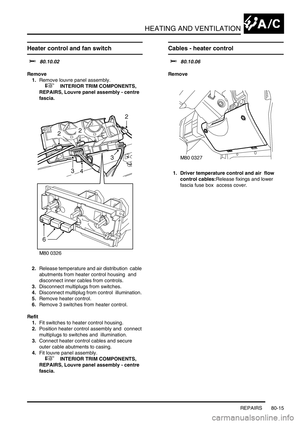
2.Release temperature and air distribution cable
abutments from heater control housing and
disconnect inner cables from controls.
3.Disconnect multiplugs from switches.
4.Disconnect multiplug from control illumination.
5.Remove heater control.
6.Remove 3 switches from heater control.
Refit
1.Fit switches to heater control housing.
2.Position heater control assembly and connect
multiplugs to switches and illumination.
3.Connect heater control cables and secure
outer cable abutments to casing.
4.Fit louvre panel assembly.
+ INTERIOR TRIM COMPONENTS,
REPAIRS, Louvre panel assembly - centre
fascia.
Cables - heater control
$% 80.10.06
Remove
1. Driver temperature control and air flow
control cables:Release fixings and lower
fascia fuse box access cover.
Page 1173 of 1529
HEATING AND VENTILATION
80-16REPAIRS
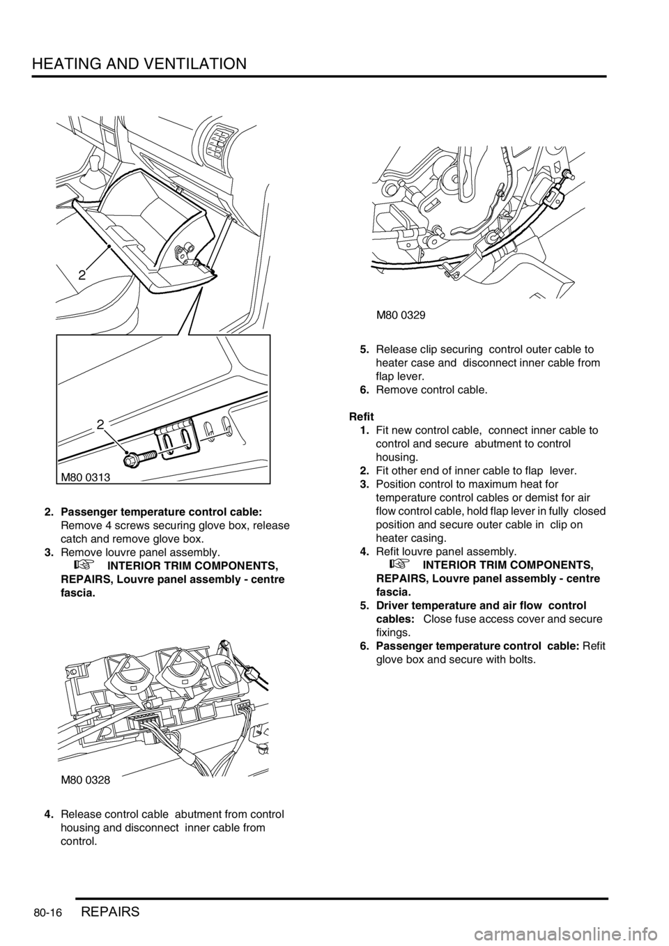
2. Passenger temperature control cable:
Remove 4 screws securing glove box, release
catch and remove glove box.
3.Remove louvre panel assembly.
+ INTERIOR TRIM COMPONENTS,
REPAIRS, Louvre panel assembly - centre
fascia.
4.Release control cable abutment from control
housing and disconnect inner cable from
control. 5.Release clip securing control outer cable to
heater case and disconnect inner cable from
flap lever.
6.Remove control cable.
Refit
1.Fit new control cable, connect inner cable to
control and secure abutment to control
housing.
2.Fit other end of inner cable to flap lever.
3.Position control to maximum heat for
temperature control cables or demist for air
flow control cable, hold flap lever in fully closed
position and secure outer cable in clip on
heater casing.
4.Refit louvre panel assembly.
+ INTERIOR TRIM COMPONENTS,
REPAIRS, Louvre panel assembly - centre
fascia.
5. Driver temperature and air flow control
cables: Close fuse access cover and secure
fixings.
6. Passenger temperature control cable: Refit
glove box and secure with bolts.
Page 1175 of 1529
HEATING AND VENTILATION
80-18REPAIRS
Refit
1.Position servo and connect operating lever.
2.Fit and tighten screws securing servo.
3.Connect multiplug to servo.
4.Position ECU assembly, fit and tighten nuts.
5.Position BCM, fit and tighten bolt.
6.Position toe board and secure with studs.
7.Position glove box, fit and tighten screws.
Switch - recirculation control
$% 80.10.21
Remove
1.Remove louvre panel assembly.
+ INTERIOR TRIM COMPONENTS,
REPAIRS, Louvre panel assembly - centre
fascia.
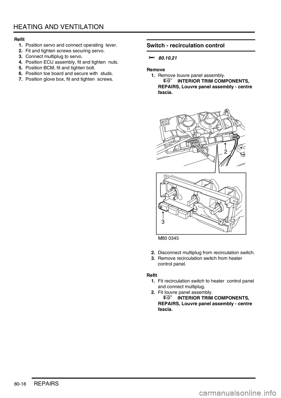
2.Disconnect multiplug from recirculation switch.
3.Remove recirculation switch from heater
control panel.
Refit
1.Fit recirculation switch to heater control panel
and connect multiplug.
2.Fit louvre panel assembly.
+ INTERIOR TRIM COMPONENTS,
REPAIRS, Louvre panel assembly - centre
fascia.
Page 1176 of 1529
HEATING AND VENTILATION
REPAIRS 80-19
Servo - air distribution control
$% 80.10.30
Remove
1.Disconnect battery earth lead.
2. RHD models: Remove heater assembly.
+ HEATING AND VENTILATION,
REPAIRS, Heater assembly - models with
air conditioning.
3. LHD models: Remove heater motor assembly.
+ HEATING AND VENTILATION,
REPAIRS, Blower assembly.
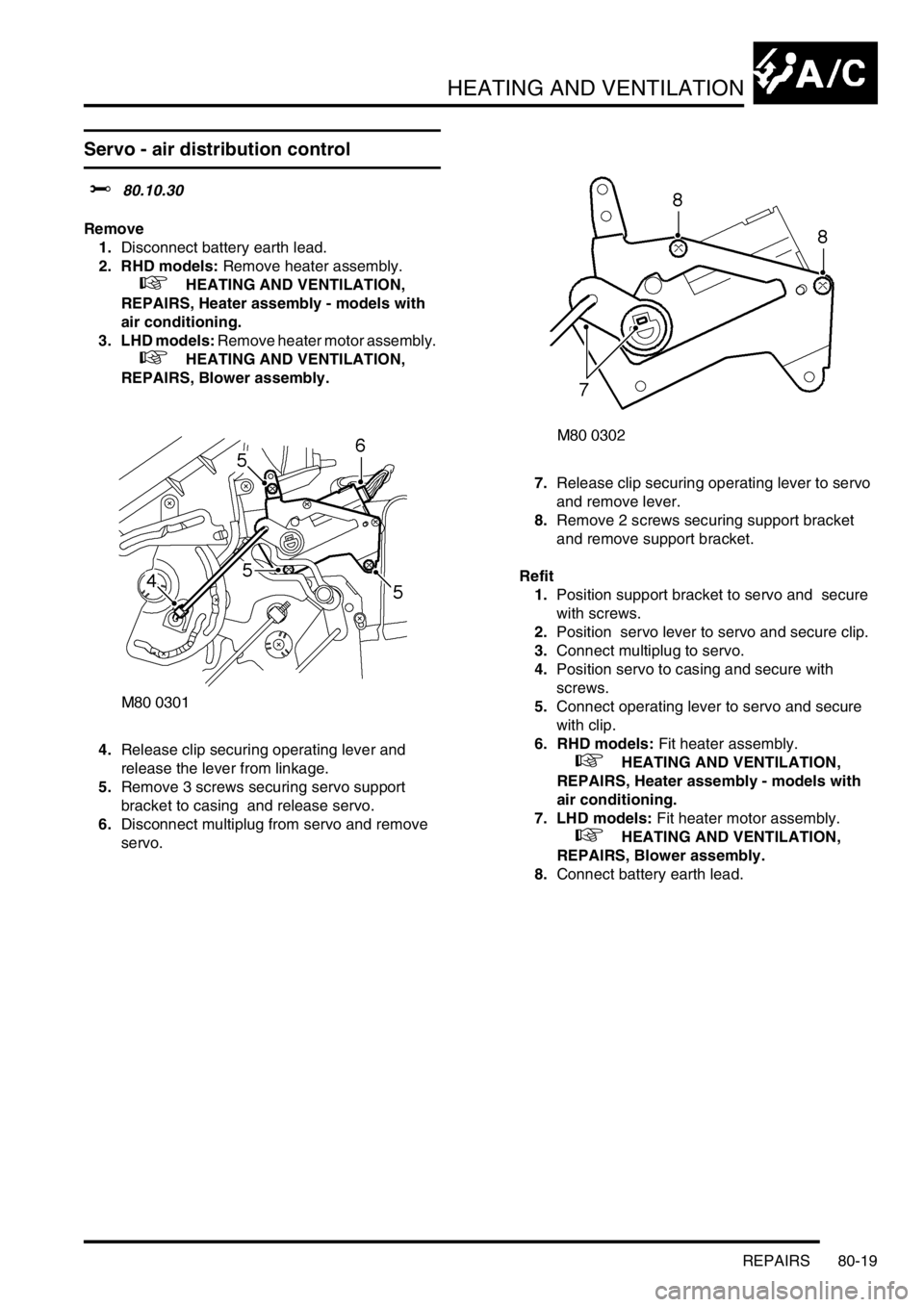
4.Release clip securing operating lever and
release the lever from linkage.
5.Remove 3 screws securing servo support
bracket to casing and release servo.
6.Disconnect multiplug from servo and remove
servo. 7.Release clip securing operating lever to servo
and remove lever.
8.Remove 2 screws securing support bracket
and remove support bracket.
Refit
1.Position support bracket to servo and secure
with screws.
2.Position servo lever to servo and secure clip.
3.Connect multiplug to servo.
4.Position servo to casing and secure with
screws.
5.Connect operating lever to servo and secure
with clip.
6. RHD models: Fit heater assembly.
+ HEATING AND VENTILATION,
REPAIRS, Heater assembly - models with
air conditioning.
7. LHD models: Fit heater motor assembly.
+ HEATING AND VENTILATION,
REPAIRS, Blower assembly.
8.Connect battery earth lead.
Page 1177 of 1529
HEATING AND VENTILATION
80-20REPAIRS
Servo - air temperature control
$% 80.10.42
Remove
1.Disconnect battery earth lead.
2. Driver side: Remove heater assembly.
+ HEATING AND VENTILATION,
REPAIRS, Heater assembly - models with
air conditioning.
3. Passenger side: Remove blower assembly.
+ HEATING AND VENTILATION,
REPAIRS, Blower assembly.
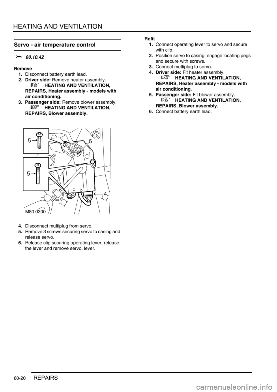
4.Disconnect multiplug from servo.
5.Remove 3 screws securing servo to casing and
release servo.
6.Release clip securing operating lever, release
the lever and remove servo. lever. Refit
1.Connect operating lever to servo and secure
with clip.
2.Position servo to casing, engage locating pegs
and secure with screws.
3.Connect multiplug to servo.
4. Driver side: Fit heater assembly.
+ HEATING AND VENTILATION,
REPAIRS, Heater assembly - models with
air conditioning.
5. Passenger side: Fit blower assembly.
+ HEATING AND VENTILATION,
REPAIRS, Blower assembly.
6.Connect battery earth lead.
Page 1179 of 1529

HEATING AND VENTILATION
80-22REPAIRS
Heater assembly - models without air
conditioning
$% 80.20.01.99
Remove
1.Drain cooling system.
l
+ COOLING SYSTEM - Td5,
ADJUSTMENTS, Drain and refill.
l
+ COOLING SYSTEM - V8,
ADJUSTMENTS, Drain and refill.
2. Diesel models: Remove 3 bolts and remove
engine cover.
3.Release clips and disconnect coolant hoses
from heater pipes.
CAUTION: Always fit plugs to open
connections to prevent contamination.
4.Remove facia assembly.
+ INTERIOR TRIM COMPONENTS,
REPAIRS, Fascia.5.Disconnect harness multiplug from heater
blower motor.
6.Remove bolt and 2 nuts securing heater
blower housing assembly to body and remove
blower.
7.Disconnect 2 drain tubes from base of heater.
Page 1180 of 1529

HEATING AND VENTILATION
REPAIRS 80-23
8.Remove 2 screws securing console bracket to
tunnel and remove bracket.
9.Release radio coaxial cable from behind heater
pipes.
10.Protect the carpet from coolant spillage.
11.Remove 4 nuts and 1 bolt securing heater to
body.
12.Remove heater from vehicle.
13.Remove 2 screws securing heater RH and LH
footwell outlet duct to heater casing and
remove ducts. 14.Remove 2 screws securing matrix pipe bracket
to heater casing.
15.Remove screw securing pipe clamp to heater
casing and remove clamp.
16.Carefully remove matrix from heater.
Refit
1.Fit matrix into heater casing.
2.Fit screws securing pipe bracket to heater
casing.
3.Fit pipe clamp and secure with screw.
4.Fit heater ducts and secure with screws.
5.Position heater assembly to vehicle, ensure
heater coolant pipe grommet is correctly
located in bulkhead and secure with nuts and
bolt.
6.Fit radio coaxial cable behind heater pipes.
7.Fit console bracket and secure with screws.
8.Connect drain tubes to base of heater.
9.Fit blower unit to heater and secure to body
with nuts and bolt.
10.Connect harness multiplug to blower motor.
11.Fit facia assembly
+ INTERIOR TRIM COMPONENTS,
REPAIRS, Fascia.
12.Connect heater hoses and secure with clips.
13. Diesel models: Fit engine cover and secure
with bolts.
14.Refill cooling system
l
+ COOLING SYSTEM - Td5,
ADJUSTMENTS, Drain and refill.
l
+ COOLING SYSTEM - V8,
ADJUSTMENTS, Drain and refill.
Page 1181 of 1529

HEATING AND VENTILATION
80-24REPAIRS
Heater assembly - models with air
conditioning
$% 80.20.01.98
Remove
1.Drain cooling system.
l
+ COOLING SYSTEM - V8,
ADJUSTMENTS, Drain and refill.
l
+ COOLING SYSTEM - Td5,
ADJUSTMENTS, Drain and refill.
2.Evacuate air conditioning system.
+ AIR CONDITIONING, REFRIGERANT
RECOVERY, RECYCLING AND
RECHARGING, Refrigerant recovery,
recycling and recharging.
3.Release 2 clips securing heater hoses to
heater and release hoses.
4.Remove 2 bolts securing air conditioning pipes
to evaporator, release pipes and discard 'O'
rings.
CAUTION: Always fit plugs to open
connections to prevent contamination.
5.Remove fascia.
+ INTERIOR TRIM COMPONENTS,
REPAIRS, Fascia.6.Remove screws securing rear heater ducting
and remove ducting.
7.Disconnect multiplug from heater motor.
8.Remove 2 nuts and bolt securing heater motor
assembly and remove motor assembly from
heater casing.
Page 1182 of 1529
HEATING AND VENTILATION
REPAIRS 80-25
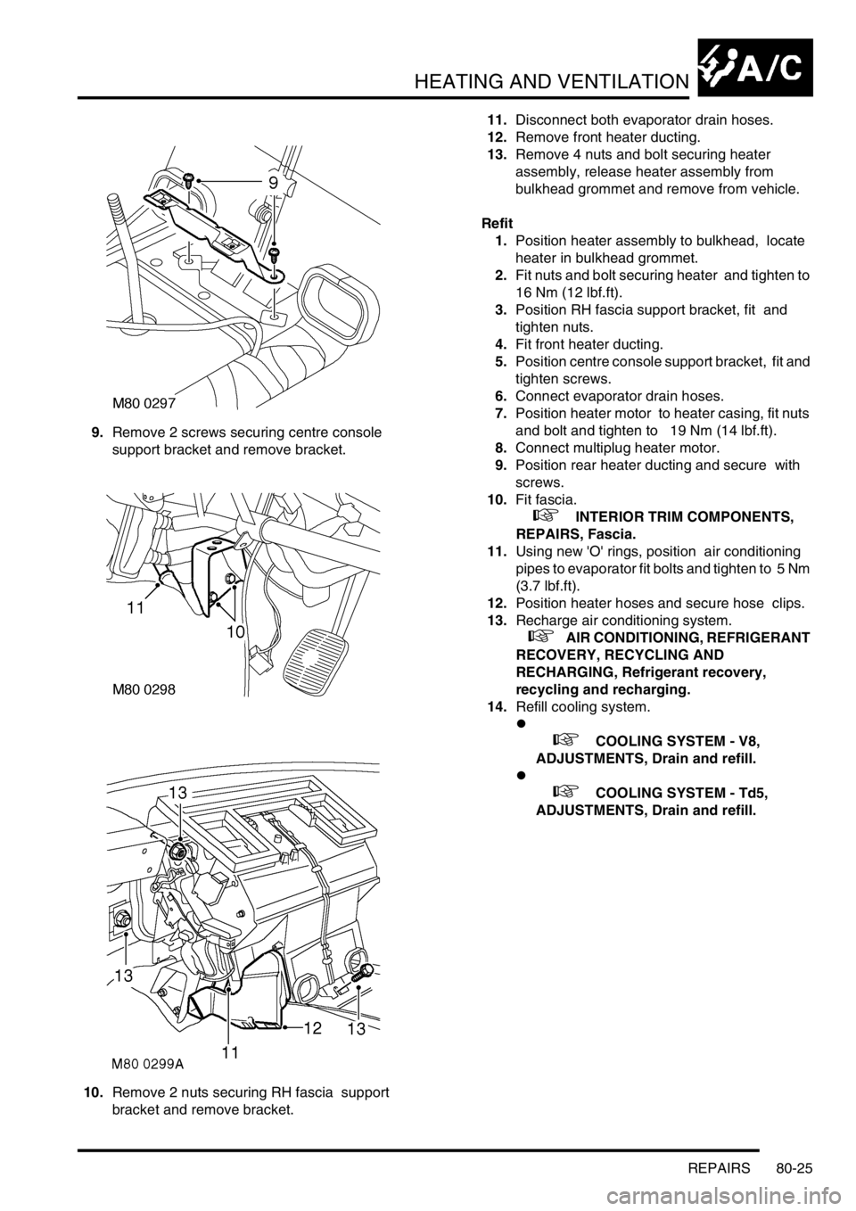
9.Remove 2 screws securing centre console
support bracket and remove bracket.
10.Remove 2 nuts securing RH fascia support
bracket and remove bracket. 11.Disconnect both evaporator drain hoses.
12.Remove front heater ducting.
13.Remove 4 nuts and bolt securing heater
assembly, release heater assembly from
bulkhead grommet and remove from vehicle.
Refit
1.Position heater assembly to bulkhead, locate
heater in bulkhead grommet.
2.Fit nuts and bolt securing heater and tighten to
16 Nm (12 lbf.ft).
3.Position RH fascia support bracket, fit and
tighten nuts.
4.Fit front heater ducting.
5.Position centre console support bracket, fit and
tighten screws.
6.Connect evaporator drain hoses.
7.Position heater motor to heater casing, fit nuts
and bolt and tighten to 19 Nm (14 lbf.ft).
8.Connect multiplug heater motor.
9.Position rear heater ducting and secure with
screws.
10.Fit fascia.
+ INTERIOR TRIM COMPONENTS,
REPAIRS, Fascia.
11.Using new 'O' rings, position air conditioning
pipes to evaporator fit bolts and tighten to 5 Nm
(3.7 lbf.ft).
12.Position heater hoses and secure hose clips.
13.Recharge air conditioning system.
+ AIR CONDITIONING, REFRIGERANT
RECOVERY, RECYCLING AND
RECHARGING, Refrigerant recovery,
recycling and recharging.
14.Refill cooling system.
l
+ COOLING SYSTEM - V8,
ADJUSTMENTS, Drain and refill.
l
+ COOLING SYSTEM - Td5,
ADJUSTMENTS, Drain and refill.