LAND ROVER DISCOVERY 1999 Workshop Manual
Manufacturer: LAND ROVER, Model Year: 1999, Model line: DISCOVERY, Model: LAND ROVER DISCOVERY 1999Pages: 1529, PDF Size: 34.8 MB
Page 821 of 1529

REAR SUSPENSION
64-12 DESCRIPTION AND OPERATION
Description - SLS
General
The Self Levelling Suspension (SLS) system is an optional fitment and comprises an Electronic Control Unit (ECU),
air supply unit, two air springs and two height sensors. The SLS system only operates on the rear suspension and is
designed to keep the vehicle level to compensate for uneven loads or when towing. The system controls the gap
between the chassis and the rear axle to a tolerance of ± 0.5 mm (0.02 in). The ride height of the rear of the vehicle
can be controlled in three modes of operation; normal ride height, Off-Road Mode (ORM) and extended mode. A
transportation mode, initiated using TestBook, is also available for moving the vehicle on a trailer.
The system is controlled electronically by an ECU which is shared with the ABS system and known as the Self
Levelling and Anti-Lock Braking System (SLABS) ECU. The system operates by using an air supply unit to inflate or
deflate the air springs to maintain a constant ride height.
An accessory remote handset is available to remotely operate the SLS system to allow easier connection and
disconnection of trailers.
Two SLS system warning lamps are located in the instrument pack. The warning lamp in the bottom left corner of the
instrument pack is the SLS warning lamp. If a fault is detected in the system, the warning lamp will illuminate
continuously in an amber colour. The warning lamp also flashes in an amber colour when the remote handset is being
used. The second warning lamp, located in the top right of the instrument pack is the ORM warning lamp. When ORM
is selected the warning lamp is continuously illuminated in an amber colour. When the SLS is between standard ride
height and ORM or in extended mode, the warning lamp will flash. Standard ride height, measured between the tip of
the axle bump stop rubber and the axle, is 61.5 mm (2.42 in). ORM ride height, measured between the tip of axle
bump stop and the axle, is 100 mm (3.93 in).
A switch is located in the group of six switches on the fascia and is used to select the ORM. The switch is non-latching
and must be depressed for a minimum of 0.5 seconds to signal the ECU that ORM has been requested.
Page 822 of 1529
REAR SUSPENSION
DESCRIPTION AND OPERATION 64-13
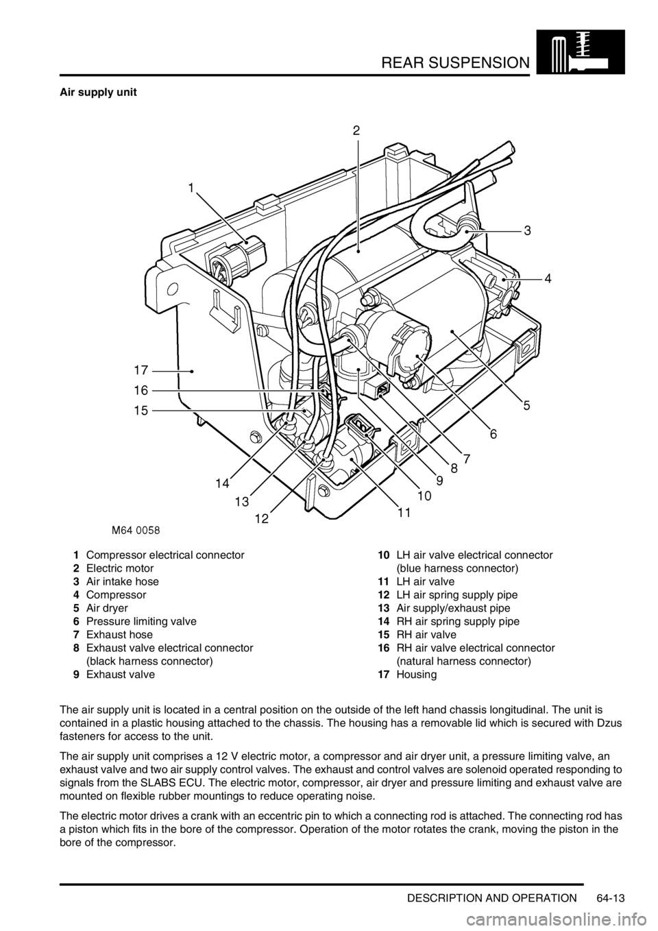
Air supply unit
1Compressor electrical connector
2Electric motor
3Air intake hose
4Compressor
5Air dryer
6Pressure limiting valve
7Exhaust hose
8Exhaust valve electrical connector
(black harness connector)
9Exhaust valve10LH air valve electrical connector
(blue harness connector)
11LH air valve
12LH air spring supply pipe
13Air supply/exhaust pipe
14RH air spring supply pipe
15RH air valve
16RH air valve electrical connector
(natural harness connector)
17Housing
The air supply unit is located in a central position on the outside of the left hand chassis longitudinal. The unit is
contained in a plastic housing attached to the chassis. The housing has a removable lid which is secured with Dzus
fasteners for access to the unit.
The air supply unit comprises a 12 V electric motor, a compressor and air dryer unit, a pressure limiting valve, an
exhaust valve and two air supply control valves. The exhaust and control valves are solenoid operated responding to
signals from the SLABS ECU. The electric motor, compressor, air dryer and pressure limiting and exhaust valve are
mounted on flexible rubber mountings to reduce operating noise.
The electric motor drives a crank with an eccentric pin to which a connecting rod is attached. The connecting rod has
a piston which fits in the bore of the compressor. Operation of the motor rotates the crank, moving the piston in the
bore of the compressor.
Page 823 of 1529

REAR SUSPENSION
64-14 DESCRIPTION AND OPERATION
The compressor is attached with Allen bolts to the motor housing and sealed with an O-ring. Attached to the
compressor is the air dryer which contains a silicate box for removing moisture from the compressed air. Air supplied
to inflate the air springs passes through the air dryer. When the air springs are deflated, the exhaust air also passes
through the air dryer, removing the moisture from the unit and expelling it to atmosphere.
Attached to end of the air dryer unit is the pressure limiting valve. The valve protects the air springs from over inflation.
The pressure limiting valve also operates when the exhaust valve is opened. The valve is pneumatically operated,
responding to air pressure applied to it.
The exhaust valve is also located with the pressure limiting valve. The exhaust valve is solenoid operated by the ECU
and directs air from the air springs and control valves to atmosphere when required.
The two air control valves for the LH and RH air springs are located at the forward end of the housing. Each valve is
connected to the compressor/air dryer unit through a shared single pipe which directs air to and from the air springs.
Each control valve is individually operated by the ECU.
All air connections to and from the air supply unit are made through the SLS air harness which is located along the
left hand chassis longitudinal.
If faults occur with the air supply unit, fault codes are stored in the SLABS ECU. These fault codes cover the
compressor power supply and the LH and RH air control valves and the exhaust valve. The current and past fault
codes can be retrieved with TestBook. TestBook can also be used to operate the compressor and the valves for
diagnostic purposes.
Air intake filter
The air intake filter is located in the left hand 'E' post, behind the tail lamp assembly. The filter comprises a plastic
moulded housing which contains two filters of differing density to remove particulate matter from the air drawn in by
the compressor. The air intake filter has a pipe which is connected to the SLS air harness by a quick release
connector. The air intake filter must be replaced as an assembly.
Air intake/Exhaust silencer
The air intake/exhaust silencer is located on the outside of the left hand chassis longitudinal, behind the air supply
unit. The silencer is an integral part of the SLS air harness and cannot be serviced individually.
The intake and exhaust air to and from the compressor passes through the silencer. The plastic moulded silencer has
two chambers. One chamber reduces system exhaust noise and the other dampens intake air pulses produced by
the compressor.
Page 824 of 1529
REAR SUSPENSION
DESCRIPTION AND OPERATION 64-15
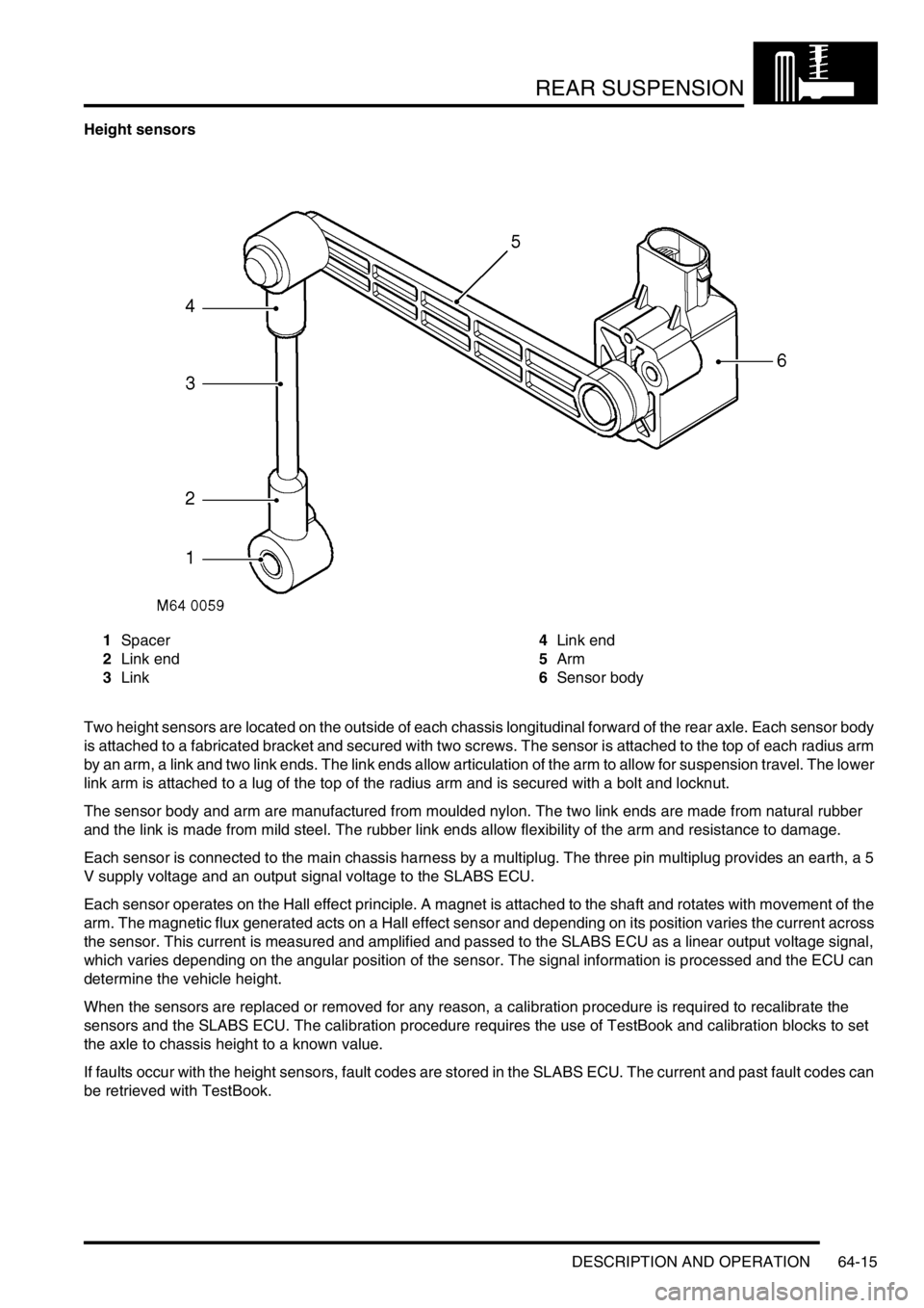
Height sensors
1Spacer
2Link end
3Link4Link end
5Arm
6Sensor body
Two height sensors are located on the outside of each chassis longitudinal forward of the rear axle. Each sensor body
is attached to a fabricated bracket and secured with two screws. The sensor is attached to the top of each radius arm
by an arm, a link and two link ends. The link ends allow articulation of the arm to allow for suspension travel. The lower
link arm is attached to a lug of the top of the radius arm and is secured with a bolt and locknut.
The sensor body and arm are manufactured from moulded nylon. The two link ends are made from natural rubber
and the link is made from mild steel. The rubber link ends allow flexibility of the arm and resistance to damage.
Each sensor is connected to the main chassis harness by a multiplug. The three pin multiplug provides an earth, a 5
V supply voltage and an output signal voltage to the SLABS ECU.
Each sensor operates on the Hall effect principle. A magnet is attached to the shaft and rotates with movement of the
arm. The magnetic flux generated acts on a Hall effect sensor and depending on its position varies the current across
the sensor. This current is measured and amplified and passed to the SLABS ECU as a linear output voltage signal,
which varies depending on the angular position of the sensor. The signal information is processed and the ECU can
determine the vehicle height.
When the sensors are replaced or removed for any reason, a calibration procedure is required to recalibrate the
sensors and the SLABS ECU. The calibration procedure requires the use of TestBook and calibration blocks to set
the axle to chassis height to a known value.
If faults occur with the height sensors, fault codes are stored in the SLABS ECU. The current and past fault codes can
be retrieved with TestBook.
Page 825 of 1529
REAR SUSPENSION
64-16 DESCRIPTION AND OPERATION
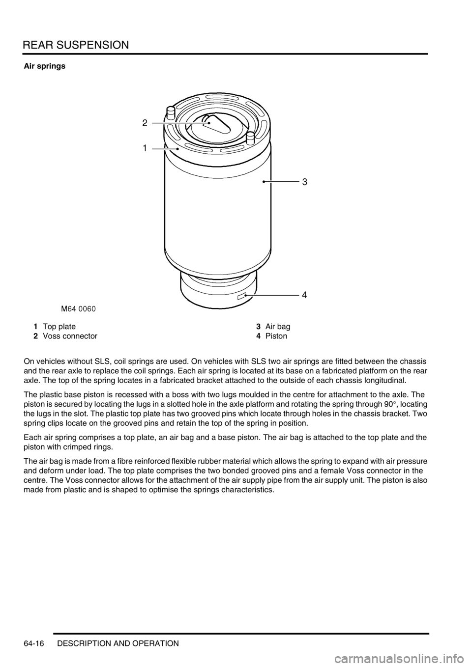
Air springs
1Top plate
2Voss connector3Air bag
4Piston
On vehicles without SLS, coil springs are used. On vehicles with SLS two air springs are fitted between the chassis
and the rear axle to replace the coil springs. Each air spring is located at its base on a fabricated platform on the rear
axle. The top of the spring locates in a fabricated bracket attached to the outside of each chassis longitudinal.
The plastic base piston is recessed with a boss with two lugs moulded in the centre for attachment to the axle. The
piston is secured by locating the lugs in a slotted hole in the axle platform and rotating the spring through 90°, locating
the lugs in the slot. The plastic top plate has two grooved pins which locate through holes in the chassis bracket. Two
spring clips locate on the grooved pins and retain the top of the spring in position.
Each air spring comprises a top plate, an air bag and a base piston. The air bag is attached to the top plate and the
piston with crimped rings.
The air bag is made from a fibre reinforced flexible rubber material which allows the spring to expand with air pressure
and deform under load. The top plate comprises the two bonded grooved pins and a female Voss connector in the
centre. The Voss connector allows for the attachment of the air supply pipe from the air supply unit. The piston is also
made from plastic and is shaped to optimise the springs characteristics.
Page 826 of 1529
REAR SUSPENSION
DESCRIPTION AND OPERATION 64-17
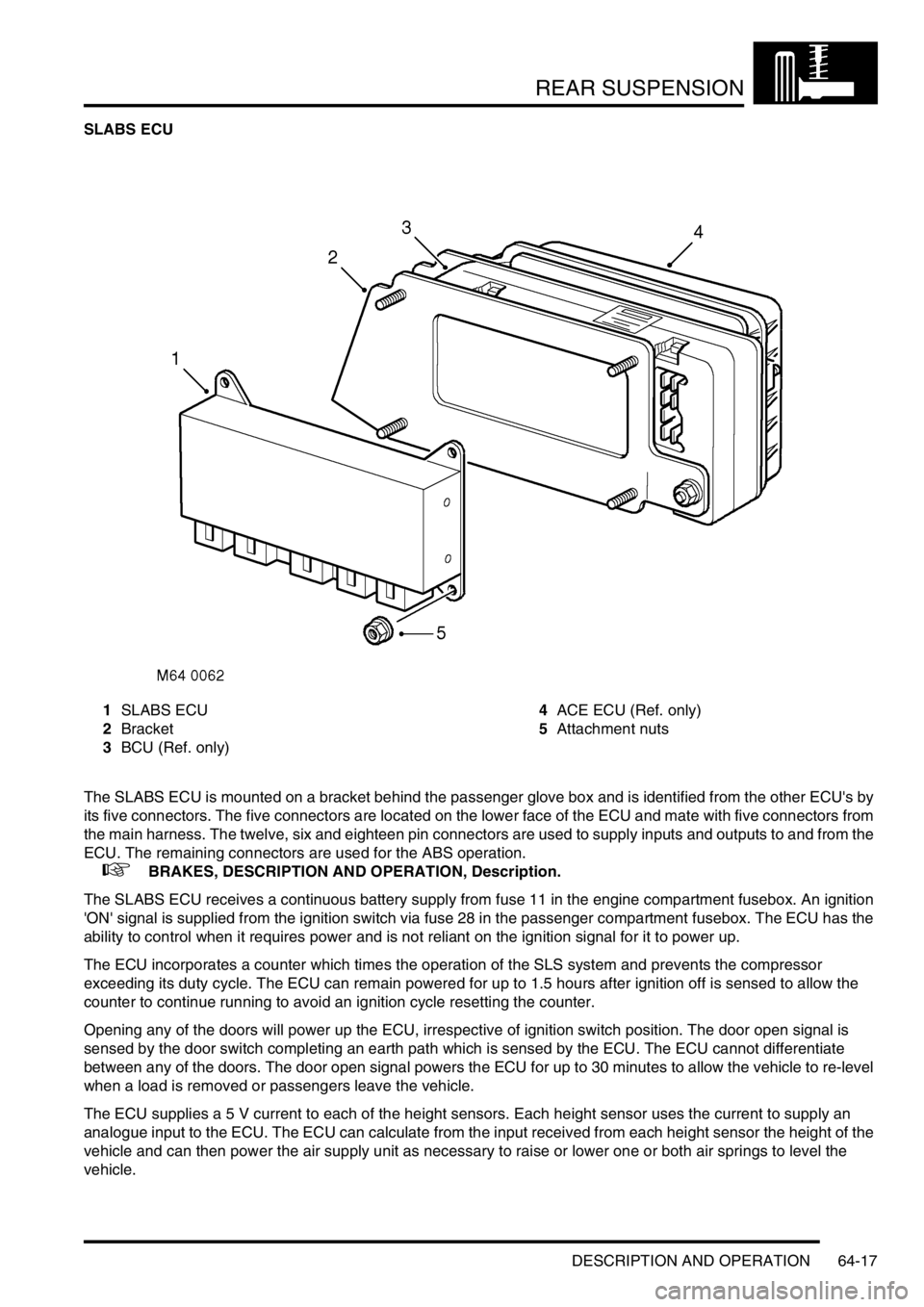
SLABS ECU
1SLABS ECU
2Bracket
3BCU (Ref. only)4ACE ECU (Ref. only)
5Attachment nuts
The SLABS ECU is mounted on a bracket behind the passenger glove box and is identified from the other ECU's by
its five connectors. The five connectors are located on the lower face of the ECU and mate with five connectors from
the main harness. The twelve, six and eighteen pin connectors are used to supply inputs and outputs to and from the
ECU. The remaining connectors are used for the ABS operation.
+ BRAKES, DESCRIPTION AND OPERATION, Description.
The SLABS ECU receives a continuous battery supply from fuse 11 in the engine compartment fusebox. An ignition
'ON' signal is supplied from the ignition switch via fuse 28 in the passenger compartment fusebox. The ECU has the
ability to control when it requires power and is not reliant on the ignition signal for it to power up.
The ECU incorporates a counter which times the operation of the SLS system and prevents the compressor
exceeding its duty cycle. The ECU can remain powered for up to 1.5 hours after ignition off is sensed to allow the
counter to continue running to avoid an ignition cycle resetting the counter.
Opening any of the doors will power up the ECU, irrespective of ignition switch position. The door open signal is
sensed by the door switch completing an earth path which is sensed by the ECU. The ECU cannot differentiate
between any of the doors. The door open signal powers the ECU for up to 30 minutes to allow the vehicle to re-level
when a load is removed or passengers leave the vehicle.
The ECU supplies a 5 V current to each of the height sensors. Each height sensor uses the current to supply an
analogue input to the ECU. The ECU can calculate from the input received from each height sensor the height of the
vehicle and can then power the air supply unit as necessary to raise or lower one or both air springs to level the
vehicle.
Page 827 of 1529
REAR SUSPENSION
64-18 DESCRIPTION AND OPERATION
When SLS compressor operation is required, the ECU provides a battery supply to energise the SLS relay located in
the engine compartment fusebox. When the relay contacts close, a 12 V supply passes through fusible link 9 in the
engine compartment fusebox, through the relay contacts and operates the air supply unit compressor. The ECU will
then supply power to operate one or both air control valve solenoids and/or the exhaust valve solenoid to inflate or
deflate the air springs as required. The compressor does not need to be powered to deflate the air springs.
The ECU also controls the operation of the SLS audible warning, the SLS warning lamp and the ORM warning lamp.
When the ignition is switched to position II, the ECU performs a three second bulb check and illuminates the SLS and
ORM warning lamps in the instrument pack to check for operation. When the system is operating or a fault is sensed
by the ECU, the ECU will operate the appropriate warning lamp and audible warning as required. The audible warning
is operated by the Body Control Unit (BCU) when it receives a signal from the SLABS ECU. The audible warning is
emitted from a speaker at the rear of the instrument pack.
Depressing the ORM switch for a minimum of 0.5 seconds, completes an earth which the ECU uses as a signal to
initiate the ORM if conditions allow. When the ECU starts ORM, the same earth that was completed by the ORM
switch is pulled to earth by the ECU to activate the ORM warning lamp. The ECU checks for a further operation of the
ORM switch by continuously and very quickly removing the earth for the ORM warning lamp. If the ORM switch is
operated for more than 0.5 seconds, the ECU will detect this and de-activate the ORM.
The SLS part of the SLABS ECU also uses the road speed data generated within the SLABS ECU by the ABS system.
Operation of ORM and extended mode are road speed sensitive and use the ABS signal to monitor the vehicle speed.
When the accessory remote handset is used for the SLS lower and raise functions, the handset transmits RF signals
which are received by the same RF receiver used for the alarm/remote door locking system. The RF receiver passes
this data as a 25 Hz PWM signal to the BCU. The BCU then transmits this data to the SLABS ECU as raise or lower
data. TestBook is required to program the BCU for remote handset operation.
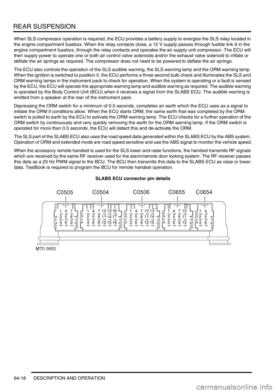
SLABS ECU connector pin details
Page 828 of 1529

REAR SUSPENSION
DESCRIPTION AND OPERATION 64-19
Failure modes
Failures are indicated by the SLS warning lamp in the bottom left corner of the instrument pack illuminating
continuously in an amber colour. The following tables show the type of system failures and their effects on the system
operation.
Height sensors
Door Switch Inputs
Connector/Pin
No.Description Input/Output
C0504
1 Battery supply Input
2 Ignition supply Input
5 K line (diagnostics) Input/Output
12 Earth Input
C0654
1 Left height sensor supply Output
2 Left height sensor earth Input
3 Left height sensor signal Input
4 Right height sensor supply Output
5 Right height sensor earth Input
6 Right height sensor signal Input
C0655
1 Driver's door switch Input
2 Passenger and tail door switches Input
3 Left air valve Output
4 Right air valve Output
5 Exhaust valve Output
6 Air compressor (SLS relay) Output
7 Audible warning Output
8 SLS warning lamp Output
11 ORM switch/ORM warning lamp Input/Output
12 Remote handset raise/lower signal Input
Connectors and pins not listed are either not used or used by the brakes system.
+ BRAKES, DESCRIPTION AND OPERATION, Description.
Failure Effect
Sensor output stuck at 5 V Vehicle will not level
Sensor output stuck at 0 V Vehicle will not level
Mechanical link between radius arm and sensor
brokenVehicle will not level
Failure Effect
Harness leads for open doors are are broken or
shorted to V Batt.Air suspension levels when one or more doors
are open
Harness leads to door(s) shorted to earth Air suspension will not level
Page 829 of 1529

REAR SUSPENSION
64-20 DESCRIPTION AND OPERATION
SLS off-road mode switch
Air supply unit air control valves
Air supply unit compressor
Failure Effect
Fault in wiring harness Off-road mode cannot be selected
Failure of off-road mode switch Off-road mode is activated when switch has not
been selected
Failure Effect
Valves open or short circuit Vehicle does not level or levels unevenly
Failure Effect
Faulty relay, harness fault or compressor fault Vehicle does not level upwards
Page 830 of 1529
REAR SUSPENSION
DESCRIPTION AND OPERATION 64-21
Operation
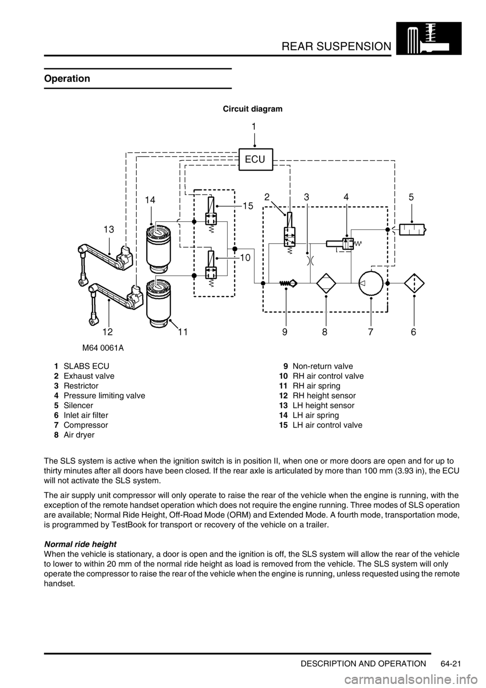
Circuit diagram
1SLABS ECU
2Exhaust valve
3Restrictor
4Pressure limiting valve
5Silencer
6Inlet air filter
7Compressor
8Air dryer9Non-return valve
10RH air control valve
11RH air spring
12RH height sensor
13LH height sensor
14LH air spring
15LH air control valve
The SLS system is active when the ignition switch is in position II, when one or more doors are open and for up to
thirty minutes after all doors have been closed. If the rear axle is articulated by more than 100 mm (3.93 in), the ECU
will not activate the SLS system.
The air supply unit compressor will only operate to raise the rear of the vehicle when the engine is running, with the
exception of the remote handset operation which does not require the engine running. Three modes of SLS operation
are available; Normal Ride Height, Off-Road Mode (ORM) and Extended Mode. A fourth mode, transportation mode,
is programmed by TestBook for transport or recovery of the vehicle on a trailer.
Normal ride height
When the vehicle is stationary, a door is open and the ignition is off, the SLS system will allow the rear of the vehicle
to lower to within 20 mm of the normal ride height as load is removed from the vehicle. The SLS system will only
operate the compressor to raise the rear of the vehicle when the engine is running, unless requested using the remote
handset.