LAND ROVER DISCOVERY 1999 Workshop Manual
Manufacturer: LAND ROVER, Model Year: 1999, Model line: DISCOVERY, Model: LAND ROVER DISCOVERY 1999Pages: 1529, PDF Size: 34.8 MB
Page 861 of 1529

BRAKES
70-8 DESCRIPTION AND OPERATION
Brakes on
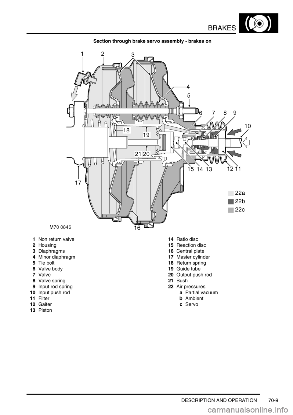
When the brake pedal is pressed, the input push rod and the piston initially move forward in the valve body. The valve
body and output rod then move with the input rod, against resistance from the return spring, to transmit the brake
pedal force to the master cylinder assembly.
During the initial movement of the piston, the valve, assisted by the valve spring, moves with the piston and closes
the vacuum port to isolate the chambers at the rear of the diaphragms from the vacuum source. Further movement
of the input push rod causes the piston to move away from the valve and open the air inlet port. This allows a restricted
flow of filtered ambient air through the air inlet port, which creates a servo pressure in the chambers at the rear of the
diaphragms. Force from the resultant pressure differential across the diaphragms is transmitted through the valve
body to the output push rod, augmenting the pressure being applied by the brake pedal. The force produced by the
diaphragms, in proportion to the input force, i.e. the boost ratio, is 5.6 : 1. The boost ratio remains constant, as the
input force from the brake pedal increases, until the limit of assistance is reached when servo pressure is equal to
ambient pressure.
Brakes held on
When the brake pedal effort is constant, opposing pressures cause the reaction disc to extrude onto the ratio disc,
which moves the piston against the valve to close the air inlet port. This prevents any further increase in servo
pressure and maintains a constant output force to the master cylinder assembly.
Brakes released
When the brake pedal is released, the input rod spring moves the input rod and piston rearwards within the valve body
to close the air inlet port and open the vacuum port. The air from the chambers at the rear of the diaphragms is then
evacuated, through the vacuum port and the chambers at the front of the diaphragms, to restore a partial vacuum in
all four chambers. Simultaneously, the return spring moves the valve body, diaphragms, output rod and input rod
rearwards to return them to their brakes off position.
Page 862 of 1529
BRAKES
DESCRIPTION AND OPERATION 70-9
Section through brake servo assembly - brakes on
1Non return valve
2Housing
3Diaphragms
4Minor diaphragm
5Tie bolt
6Valve body
7Valve
8Valve spring
9Input rod spring
10Input push rod
11Filter
12Gaiter
13Piston14Ratio disc
15Reaction disc
16Central plate
17Master cylinder
18Return spring
19Guide tube
20Output push rod
21Bush
22Air pressures
aPartial vacuum
bAmbient
cServo
Page 863 of 1529
BRAKES
70-10 DESCRIPTION AND OPERATION
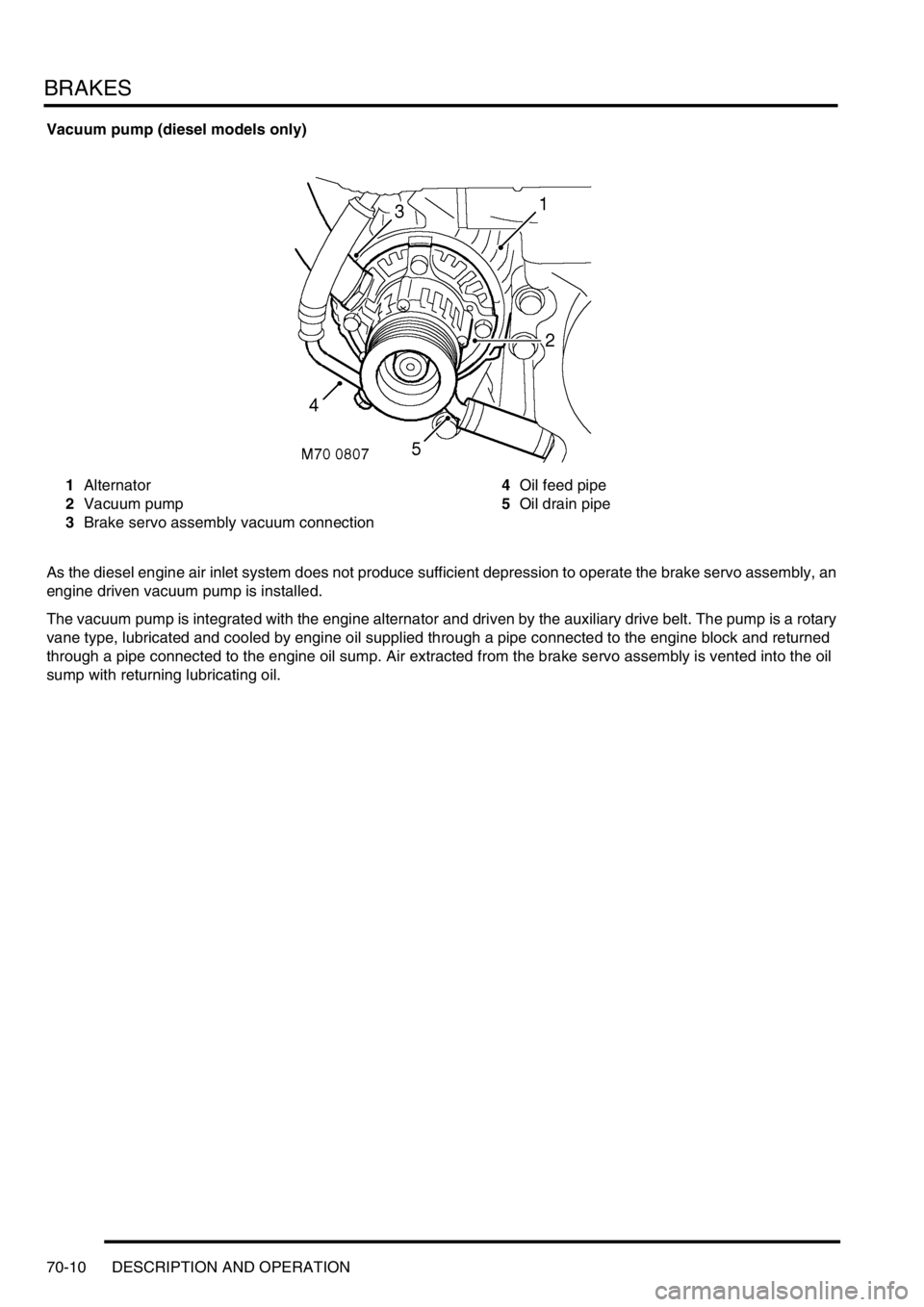
Vacuum pump (diesel models only)
1Alternator
2Vacuum pump
3Brake servo assembly vacuum connection4Oil feed pipe
5Oil drain pipe
As the diesel engine air inlet system does not produce sufficient depression to operate the brake servo assembly, an
engine driven vacuum pump is installed.
The vacuum pump is integrated with the engine alternator and driven by the auxiliary drive belt. The pump is a rotary
vane type, lubricated and cooled by engine oil supplied through a pipe connected to the engine block and returned
through a pipe connected to the engine oil sump. Air extracted from the brake servo assembly is vented into the oil
sump with returning lubricating oil.
Page 864 of 1529
BRAKES
DESCRIPTION AND OPERATION 70-11
Master cylinder assembly
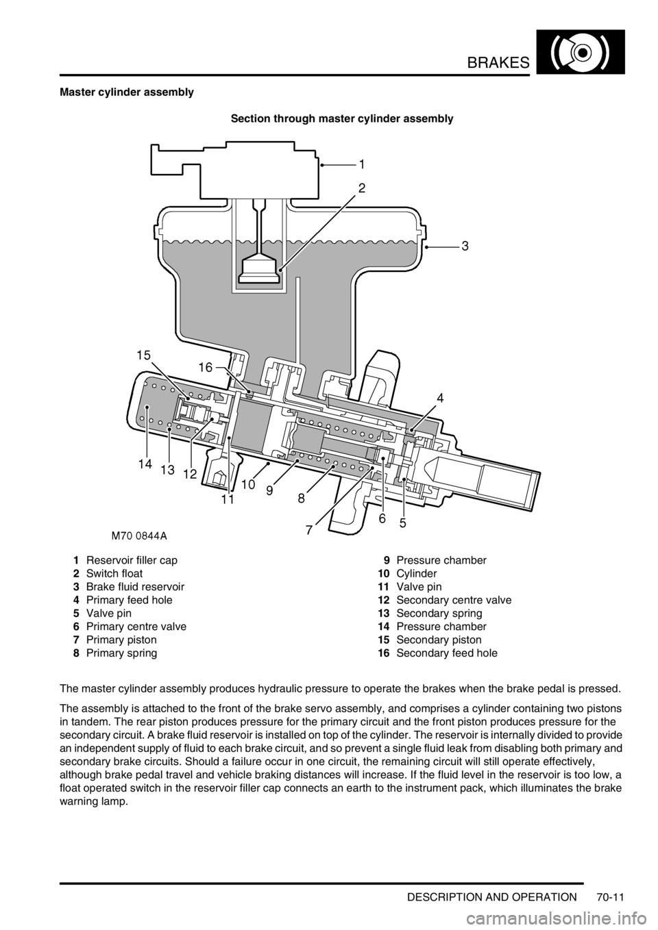
Section through master cylinder assembly
1Reservoir filler cap
2Switch float
3Brake fluid reservoir
4Primary feed hole
5Valve pin
6Primary centre valve
7Primary piston
8Primary spring9Pressure chamber
10Cylinder
11Valve pin
12Secondary centre valve
13Secondary spring
14Pressure chamber
15Secondary piston
16Secondary feed hole
The master cylinder assembly produces hydraulic pressure to operate the brakes when the brake pedal is pressed.
The assembly is attached to the front of the brake servo assembly, and comprises a cylinder containing two pistons
in tandem. The rear piston produces pressure for the primary circuit and the front piston produces pressure for the
secondary circuit. A brake fluid reservoir is installed on top of the cylinder. The reservoir is internally divided to provide
an independent supply of fluid to each brake circuit, and so prevent a single fluid leak from disabling both primary and
secondary brake circuits. Should a failure occur in one circuit, the remaining circuit will still operate effectively,
although brake pedal travel and vehicle braking distances will increase. If the fluid level in the reservoir is too low, a
float operated switch in the reservoir filler cap connects an earth to the instrument pack, which illuminates the brake
warning lamp.
Page 865 of 1529

BRAKES
70-12 DESCRIPTION AND OPERATION
Brakes applied
When the brake pedal is pressed, the output rod in the brake servo assembly pushes the primary piston along the
cylinder bore. This produces pressure in the primary pressure chamber which, in conjunction with the primary spring,
overcomes the secondary spring and simultaneously moves the secondary piston along the cylinder bore. The initial
movement of the pistons, away from the piston stops, closes the primary and secondary centre valves. Further
movement of the pistons then pressurizes the fluid in the primary and secondary pressure chambers, and thus the
brake circuits. The fluid in the chambers behind the pistons is unaffected by movement of the pistons and can flow
unrestricted through the feed holes between the chambers and the reservoir.
Brakes released
When the brake pedal is released, the primary and secondary springs push the pistons back down the bore of the
cylinder. The rapid movement of the pistons cause partial vacuums to form in the pressure chambers, which opens
the centre valves and allows fluid to circulate unrestricted between the two hydraulic circuits and the reservoir. When
the pistons reach the brakes off position, the centre valves are held open by the piston stops.
Page 866 of 1529
BRAKES
DESCRIPTION AND OPERATION 70-13
ABS modulator
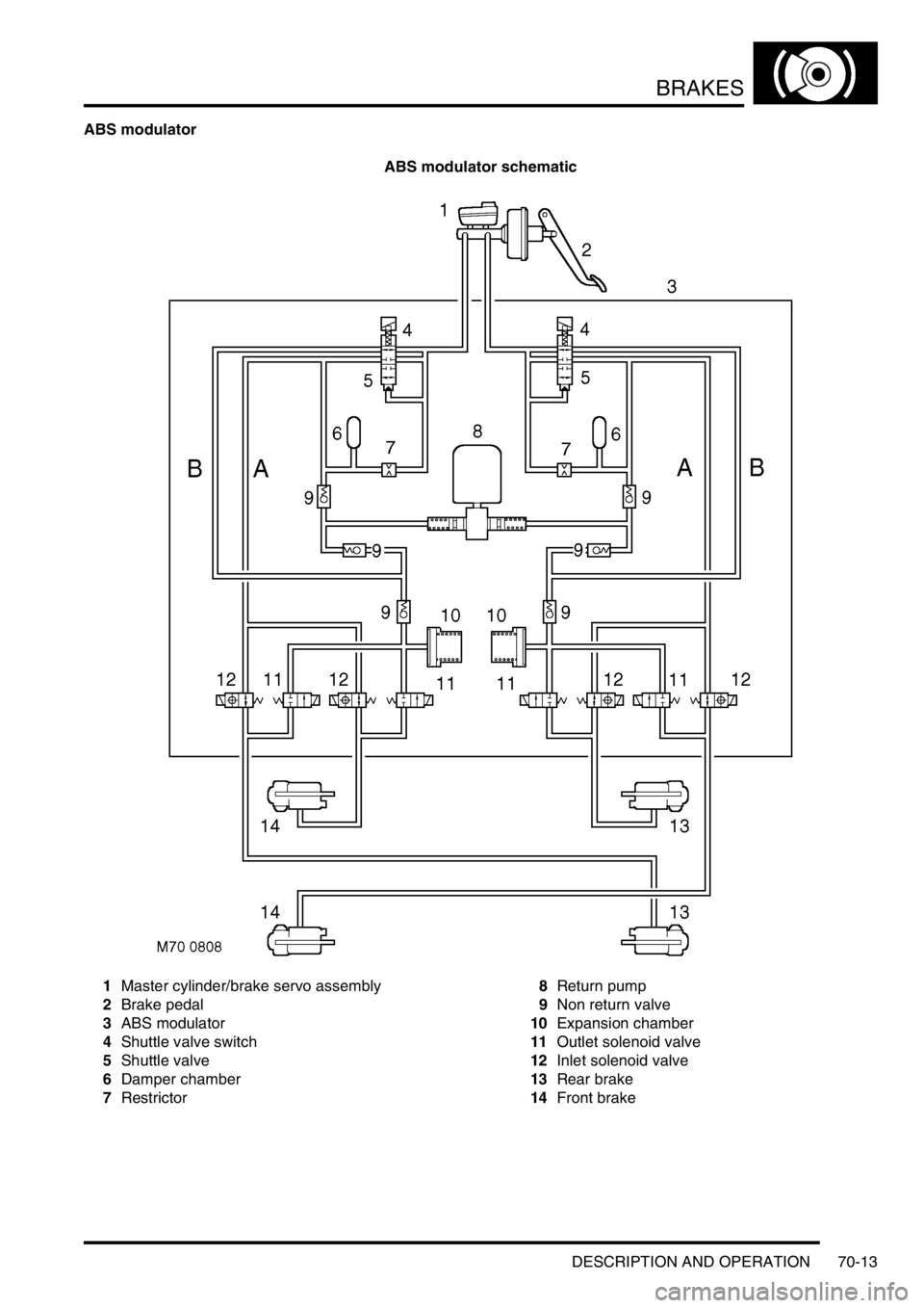
ABS modulator schematic
1Master cylinder/brake servo assembly
2Brake pedal
3ABS modulator
4Shuttle valve switch
5Shuttle valve
6Damper chamber
7Restrictor8Return pump
9Non return valve
10Expansion chamber
11Outlet solenoid valve
12Inlet solenoid valve
13Rear brake
14Front brake
Page 867 of 1529

BRAKES
70-14 DESCRIPTION AND OPERATION
The ABS modulator is a 4 channel unit that controls the supply of hydraulic pressure to the brakes in response to
inputs from the SLABS ECU. The modulator is attached by three mounting bushes to a bracket on the LH inner front
wing, and connected to the primary and secondary hydraulic circuits downstream of the master cylinder assembly.
Three electrical connectors link the ABS modulator to the vehicle wiring.
Passages within the ABS modulator, separated into primary and secondary circuits, connect to the various internal
components that control the supply of hydraulic pressure to the brakes:
lShuttle valves and non return valves control the flow through the internal circuits.
lShuttle valve switches, connected in series to the SLABS ECU, provide a brakes on/off signal.
lA damper chamber and restrictor are included in each circuit to refine system operation.
lInlet and outlet solenoid valves control the flow to the individual brakes.
lAn expansion chamber is connected to each circuit to absorb pressure.
lA return pump is connected to both circuits to provide a pressure source.
The ABS modulator has three operating modes: Normal braking, ABS braking and active braking.
Normal braking mode
When the brake pedal is pressed, pressurised fluid from the master cylinder assembly moves the shuttle valves to
open lines 'A' and close the shuttle valve switches. Pressurised fluid then flows through the open inlet solenoid valves
to operate the brakes. The closed shuttle valve switches supply a brakes on signal to the SLABS ECU. If the SLABS
ECU determines that EBD is necessary, it energises the inlet solenoid valves for the brakes of one axle. The inlet
solenoid valves close to isolate the brakes from any further increase in hydraulic pressure.
ABS braking mode
When in the normal braking mode, if the SLABS ECU determines that ABS braking is necessary, it energises the inlet
and outlet solenoid valves of the related brake and starts the return pump. The inlet solenoid valve closes to isolate
the brake from pressurised fluid; the outlet solenoid valve opens to release pressure from the brake into the expansion
chamber and the return pump circuit. The brake releases and the wheel begins to accelerate. The SLABS ECU then
operates the inlet and outlet solenoid valves to control the supply of hydraulic pressure to the brake and apply the
maximum braking effort (for the available traction) without locking the wheel.
Active braking mode
When ETC or HDC are enabled, and the SLABS ECU determines that active braking is necessary, it starts the return
pump. Hydraulic fluid, drawn from the reservoirs through the master cylinder, shuttle valves and lines 'B', is
pressurised by the return pump and supplied to lines 'A'. The SLABS ECU then operates the inlet and outlet solenoid
valves to control the supply of hydraulic pressure to the individual brakes and slow the wheel(s).
Page 868 of 1529
BRAKES
DESCRIPTION AND OPERATION 70-15
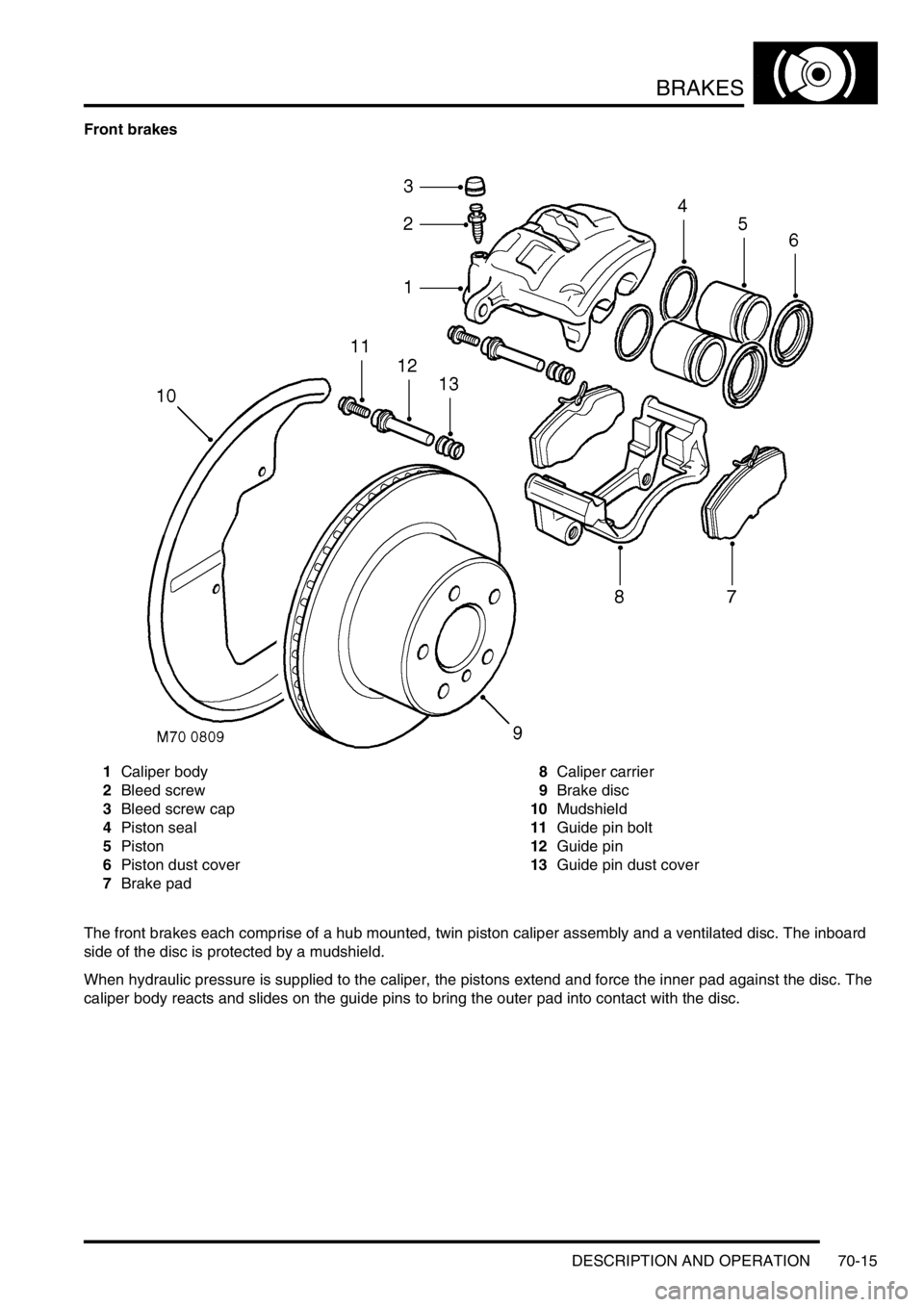
Front brakes
1Caliper body
2Bleed screw
3Bleed screw cap
4Piston seal
5Piston
6Piston dust cover
7Brake pad8Caliper carrier
9Brake disc
10Mudshield
11Guide pin bolt
12Guide pin
13Guide pin dust cover
The front brakes each comprise of a hub mounted, twin piston caliper assembly and a ventilated disc. The inboard
side of the disc is protected by a mudshield.
When hydraulic pressure is supplied to the caliper, the pistons extend and force the inner pad against the disc. The
caliper body reacts and slides on the guide pins to bring the outer pad into contact with the disc.
Page 869 of 1529
BRAKES
70-16 DESCRIPTION AND OPERATION
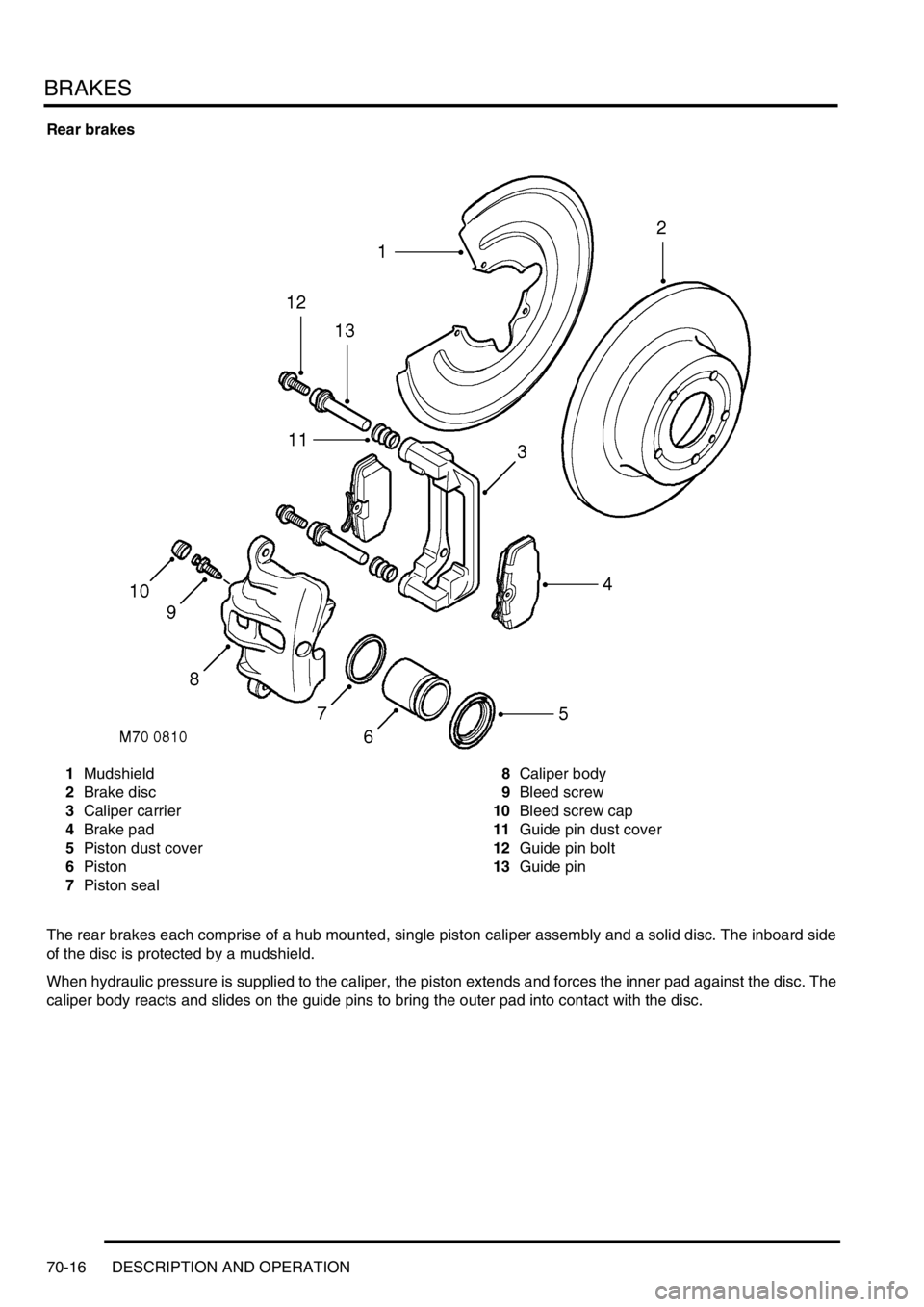
Rear brakes
1Mudshield
2Brake disc
3Caliper carrier
4Brake pad
5Piston dust cover
6Piston
7Piston seal8Caliper body
9Bleed screw
10Bleed screw cap
11Guide pin dust cover
12Guide pin bolt
13Guide pin
The rear brakes each comprise of a hub mounted, single piston caliper assembly and a solid disc. The inboard side
of the disc is protected by a mudshield.
When hydraulic pressure is supplied to the caliper, the piston extends and forces the inner pad against the disc. The
caliper body reacts and slides on the guide pins to bring the outer pad into contact with the disc.
Page 870 of 1529
BRAKES
DESCRIPTION AND OPERATION 70-17
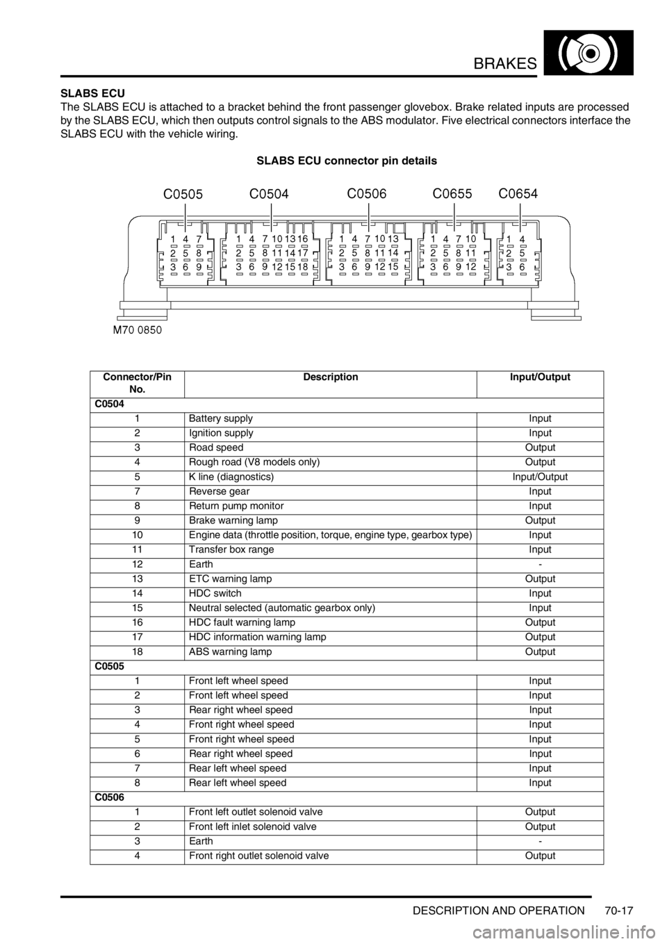
SLABS ECU
The SLABS ECU is attached to a bracket behind the front passenger glovebox. Brake related inputs are processed
by the SLABS ECU, which then outputs control signals to the ABS modulator. Five electrical connectors interface the
SLABS ECU with the vehicle wiring.
SLABS ECU connector pin details
Connector/Pin
No.Description Input/Output
C0504
1 Battery supply Input
2 Ignition supply Input
3 Road speed Output
4 Rough road (V8 models only) Output
5 K line (diagnostics) Input/Output
7 Reverse gear Input
8 Return pump monitor Input
9 Brake warning lamp Output
10 Engine data (throttle position, torque, engine type, gearbox type) Input
11 Transfer box range Input
12 Earth-
13 ETC warning lamp Output
14 HDC switch Input
15 Neutral selected (automatic gearbox only) Input
16 HDC fault warning lamp Output
17 HDC information warning lamp Output
18 ABS warning lamp Output
C0505
1 Front left wheel speed Input
2 Front left wheel speed Input
3 Rear right wheel speed Input
4 Front right wheel speed Input
5 Front right wheel speed Input
6 Rear right wheel speed Input
7 Rear left wheel speed Input
8 Rear left wheel speed Input
C0506
1 Front left outlet solenoid valve Output
2 Front left inlet solenoid valve Output
3Earth-
4 Front right outlet solenoid valve Output