sensor LAND ROVER DISCOVERY 2002 Owners Manual
[x] Cancel search | Manufacturer: LAND ROVER, Model Year: 2002, Model line: DISCOVERY, Model: LAND ROVER DISCOVERY 2002Pages: 1672, PDF Size: 46.1 MB
Page 416 of 1672

ENGINE MANAGEMENT SYSTEM - TD5
DESCRIPTION AND OPERATION 18-1-23
The FT sensor can fail the following ways or supply incorrect signal:
lSensor open circuit.
lShort circuit to vehicle supply.
lShort circuit to earth.
lSensor fitted incorrectly.
In the event of a FT sensor signal failure any of the following symptoms may be observed:
lDifficult cold start.
lDifficult hot start.
lDriveability concern.
Page 423 of 1672

ENGINE MANAGEMENT SYSTEM - TD5
18-1-30 DESCRIPTION AND OPERATION
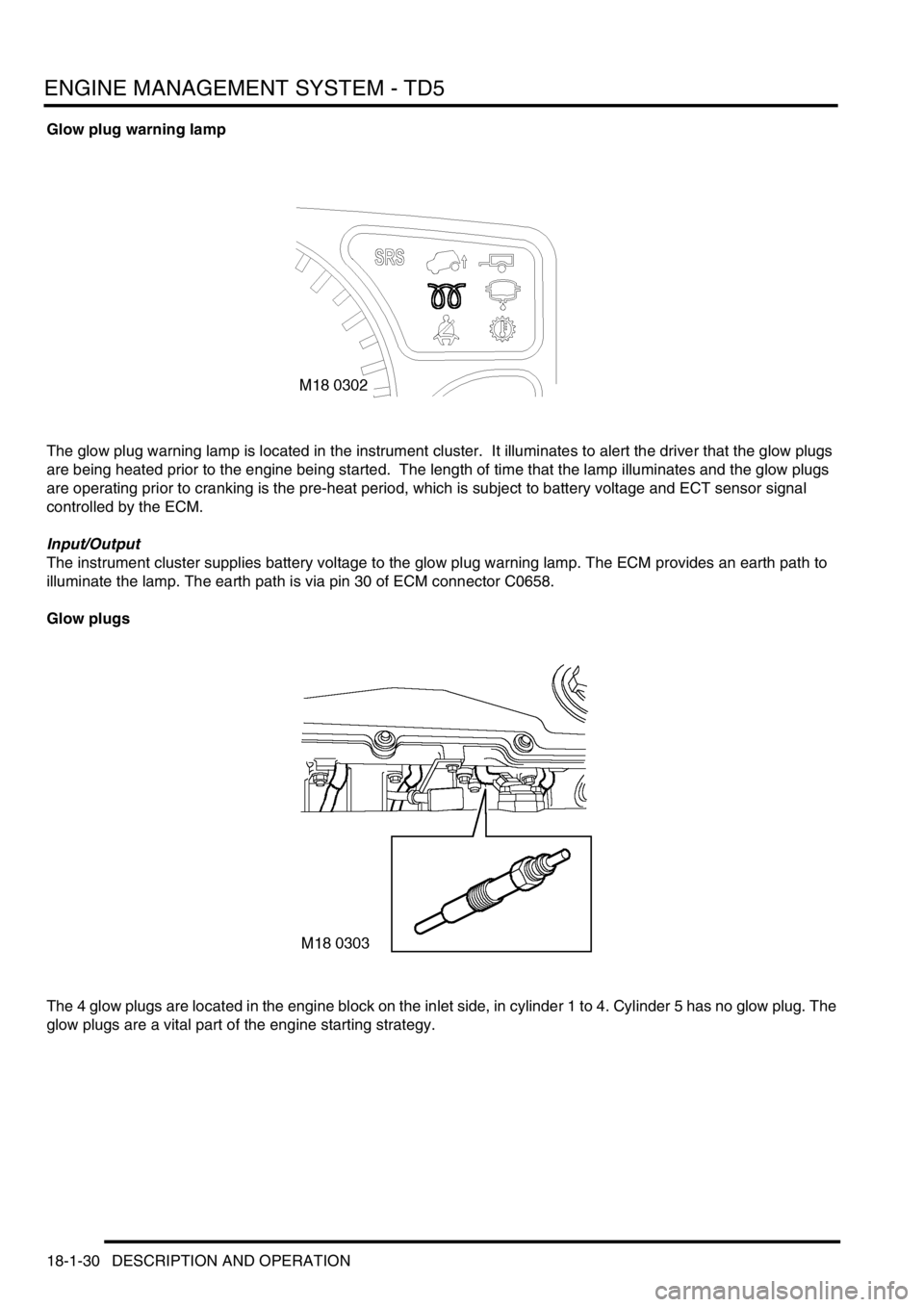
Glow plug warning lamp
The glow plug warning lamp is located in the instrument cluster. It illuminates to alert the driver that the glow plugs
are being heated prior to the engine being started. The length of time that the lamp illuminates and the glow plugs
are operating prior to cranking is the pre-heat period, which is subject to battery voltage and ECT sensor signal
controlled by the ECM.
Input/Output
The instrument cluster supplies battery voltage to the glow plug warning lamp. The ECM provides an earth path to
illuminate the lamp. The earth path is via pin 30 of ECM connector C0658.
Glow plugs
The 4 glow plugs are located in the engine block on the inlet side, in cylinder 1 to 4. Cylinder 5 has no glow plug. The
glow plugs are a vital part of the engine starting strategy.
Page 431 of 1672

ENGINE MANAGEMENT SYSTEM - TD5
18-1-38 DESCRIPTION AND OPERATION
Operation
Engine management
The ECM controls the operation of the engine using stored information within its memory. This guarantees optimum
performance from the engine in terms of torque delivery, fuel consumption and exhaust emissions in all operating
conditions, while still giving optimum driveability.
The ECM will receive information from its sensors under all operating conditions, especially during:
lCold starting.
lHot starting.
lIdle.
lWide open throttle.
lAcceleration.
lAdaptive strategy.
lBackup strategy for sensor failures.
The ECM receives information from various sensors to determine the current operating state of the engine. The ECM
then refers this information to stored values in its memory and makes any necessary changes to optimise air/fuel
mixture and fuel injection timing. The ECM controls the air/fuel mixture and fuel injection timing via the Electronic Unit
Injectors (EUI), by the length of time the EUI's are to inject fuel into the cylinder. This is a rolling process and is called
adaptive strategy. By using this adaptive strategy the ECM is able to control the engine to give optimum driveability
under all operating conditions.
During cold start conditions the ECM uses ECT information to allow more fuel to be injected into the cylinders, this
combined with the glow plug timing strategy supplied by the ECM facilitates good cold starting.
During hot start conditions the ECM uses ECT and FT information to implement the optimum fuelling strategy to
facilitate good hot starting.
During idle and wide open throttle conditions the ECM uses mapped information within its memory to respond to input
information from the throttle pedal position sensor to implement the optimum fuelling strategy to facilitate idle and wide
open throttle.
To achieve an adaptive strategy for acceleration the ECM uses input information from the CKP sensor, TP sensor,
ECT sensor, MAP/ IAT sensor, and the FT sensor. This is compared to mapped information within its memory to
implement the optimum fuelling strategy to facilitate acceleration.
Immobilisation system
When the starter switch is turned on, the BCU sends a unique security code to the ECM. The ECM must accept this
code before it will allow the engine to operate. If the ECM receives no security code or the ECM receives the incorrect
security code, then the ECM allows the engine to run for 0.5 seconds only. During this operation all other ECM
functions remain as normal.
The ECM operates immobilisation in three states:
l'New.'
l'Secure'.
l'No Code'.
When an ECM is unconfigured it will operate in the 'New' state. When an unconfigured ECM is installed the engine
can be started and operated once only, then the ECM has to be re-configured to either 'secure' or 'no code'
configuration depending on whether a security system is fitted to the vehicle. This is achieved by using TestBook.
Page 432 of 1672

ENGINE MANAGEMENT SYSTEM - TD5
DESCRIPTION AND OPERATION 18-1-39
With the ECM in a 'Secure' state, it will not function unless an alarm system is fitted to the vehicle. A 'Secure' ECM
cannot be configured into a 'No Code' ECM.
With the ECM in a 'No Code' state, it does not require an alarm system to be fitted to allow the engine to operate. If
the ECM senses that an alarm system is fitted it will not start. A 'No Code' ECM can be configured to a 'Secure' ECM
using TestBook. A 'Secure' ECM can not be configured to a 'No Code' state.
Setting up of the ECM immobilisation configurations can only be performed using TestBook.
If a vehicle stalls immediately after starting it is possible that it has been immobilised. This means either:
lThe ECM was configured as 'No Code' but the ECM is receiving a code at its alarm input pin.
lThe ECM received an incorrect code.
lThe ECM was expecting a security code but did not receive one at its alarm input pin.
Fuel delivery/injection control
The fuel delivery/injection control delivers a precise amount of finely atomised fuel to mix with the air in the
combustion chamber to create a controlled explosion.
To precisely control fuel delivery and control fuel injection, the following input conditions must be met:
lCKP information.
lInjection timing map information.
lFT information.
lECT information.
The ECM monitors the conditions required for optimum combustion of fuel in the cylinder from the various sensors
around the engine and then compares it against stored information. From this calculation the ECM can adjust the
quantity and timing of the fuel being delivered to the cylinder.
The ECM uses CKP information as follows:
lTo calculate engine speed.
lTo determine engine crankshaft position.
Engine speed and crankshaft position allows the ECM to determine fuel injection timing.
The ECM also uses ECT information and FT sensor information to allow optimum fuel delivery and injection control
for all engine coolant and fuel temperatures.
Turbocharger control
Turbocharger control is vital to ensure the turbocharger does not over boost the engine. Within the turbocharger is a
wastegate, which when operated by the turbocharger wastegate modulator will open and close a bypass valve
regulating boost pressure.
The turbocharger wastegate modulator, via the ECM, controls boost pressure under the following conditions:
lAcceleration.
lWide open throttle.
lIdle.
lOverrun.
The turbocharger wastegate modulator receives a battery voltage supply from the main relay. The ECM supplies the
earth path in the form of a pulse width modulation (PWM) signal. This signal allows the turbocharger wastegate
modulator to open and close the wastegate. A proportion of the exhaust gas can bypass the turbocharger through
the wastegate, regulating boost pressure.
Page 435 of 1672

ENGINE MANAGEMENT SYSTEM - TD5
18-1-42 DESCRIPTION AND OPERATION
Cruise control resumption
Cruise control can be resumed at the previously set speed, provided the set speed has not been erased from the
ECM's memory as described above.
To resume cruise control operation to the previously set speed, depress the RES switch once when the following
conditions are met:
lA set speed is stored in the ECM.
lVehicle speed is above 22 mph (35 km/h).
lThe brake pedal is not pressed.
lThe clutch pedal is not pressed (manual transmission only).
lThe transmission is not in Park, Reverse or Neutral (automatic transmission only).
The ECM activates the cruise control system at the stored speed.
Accelerating while cruise control is active
There are three ways of increasing vehicle speed when cruise control is active:
lTemporarily increase vehicle speed (e.g. when overtaking another vehicle).
lIncrease vehicle set speed in 1 mph (1.5 km/h) increments.
lIncrease vehicle set speed.
To temporarily increase vehicle speed press the accelerator pedal until the desired speed is reached.
When the accelerator pedal is released, the vehicle coasts back to the set speed. When it reaches the set speed,
cruise control operation continues.
To increase the vehicle set speed in 1 mph (1.5 km/h) increments, tap the SET+ switch. Each tap on the switch
increases vehicle speed.
To increase the vehicle set speed, press and hold the SET+ switch until the desired set speed is reached.
Vehicle set speed will increase if the following conditions are met:
lThe vehicle is under cruise control operation.
lVehicle speed is above 22 mph (35 km/h).
lThe brake pedal is not pressed.
lThe clutch pedal is not pressed (manual transmission only).
lThe transmission is not in Park, Reverse or Neutral (automatic transmission only).
The vehicle responds as follows:
lIf the driver accelerates using the throttle pedal, the ECM increases vehicle speed using the TP sensor signal.
When the driver releases the accelerator pedal, the vehicle returns to the set speed.
lIf the SET+ switch is tapped the stored speed and vehicle speed increases by 1 mph (1.5 km/h) per tap on the
switch.
lIf the driver presses and holds the SET+ switch the vehicle speed will increase and will hold the speed when the
switch is released.
Switching off cruise control
Switching off cruise control allows the driver to regain control of vehicle speed, and erases the set road speed from
the ECM's memory.
To switch off cruise control, press the cruise control master switch to the off position.
When the cruise control master switch is switched off, the ECM deactivates cruise control and the driver regains
control of vehicle speed.
Page 436 of 1672

ENGINE MANAGEMENT SYSTEM - TD5
DESCRIPTION AND OPERATION 18-1-43
Air Conditioning (A/C)
The ECM controls operation of the A/C compressor and the engine's electric cooling fan in response to requests from
the Automatic Temperature Control (ATC) ECU.
A/C request
When the ATC ECU supplies the ECM with an A/C request, the ECM energises the compressor clutch relay. The
compressor clutch relay is located in the engine compartment fuse box. It is a four pin normally open relay. This means
that the relay must be energised to drive the compressor clutch. During periods of high driver demand such as hard
acceleration or maximum rev/min the ECM will disable the compressor clutch for a short time. This is to reduce the
load on the engine.
The operation of the A/C request is via a switch being connected to earth. Voltage is supplied via pin 9 of connector
C0658 of the ECM, at the point at which the switch is pressed the connection to the earth path is made and the
compressor clutch is engaged.
The ECM provides the earth for the relay windings to allow the compressor clutch relay contacts to close and the
compressor clutch drive to receive battery voltage. The ECM uses a transistor as a switch to generate an open circuit
in the earth path of the relay windings. When the ECM closes down the earth path, the return spring in the relay will
pull the contacts apart to shut down the compressor clutch drive. Fuse 6, located in the engine compartment fuse box,
provides voltage to the compressor clutch relay switching contacts. The relay windings are supplied with battery
voltage from the main relay, also located in the engine compartment fuse box. The earth path for the relay windings
is via pin 29 of the ECM connector C0658. When the relay is energised the output from the switching contacts is
directly to the compressor clutch.
Cooling fan request
The A/C fan request is an input to the ECM from the ATC ECU to request that the engine's electric cooling fan is
activated to provide additional cooling for the A/C condenser.
The cooling fan relay is located in the engine compartment fuse box and is also controlled by the ECM. It is a four pin
normally open relay. This means that the relay must be energised to drive the cooling fan. The cooling fan is used
especially when the engine is operating at excessively high temperatures. It is also used as a part of the ECM backup
strategy if the ECT sensor fails.
The operation of the cooling fan request is via a switch being connected to earth. Voltage is supplied via pin 23 of
connector C0658 of the ECM, at the point at when the switch is pressed the connection to the earth path is made and
the cooling fan is engaged.
The ECM provides the earth for the cooling fan relay windings to allow the relay contacts to close and the cooling fan
motor to receive battery voltage. The ECM uses a transistor as a switch to generate an open circuit in the earth path
of the relay windings. When the ECM closes down the earth path, the return spring in the relay will pull the contacts
apart to shut down the cooling fan motor drive. Input to the A/C cooling fan relay switching contacts is via fuse 4
located in the engine compartment fuse box. The relay windings are supplied with battery voltage from the main relay,
also located in the engine compartment fuse box. The earth path for the relay windings is via pin 4 of the ECM
connector C0658. When the relay is energised the output from the switching contacts is directly to the cooling fan
motor.
Page 440 of 1672

ENGINE MANAGEMENT SYSTEM - TD5
REPAIRS 18-1-47
REPAIRS
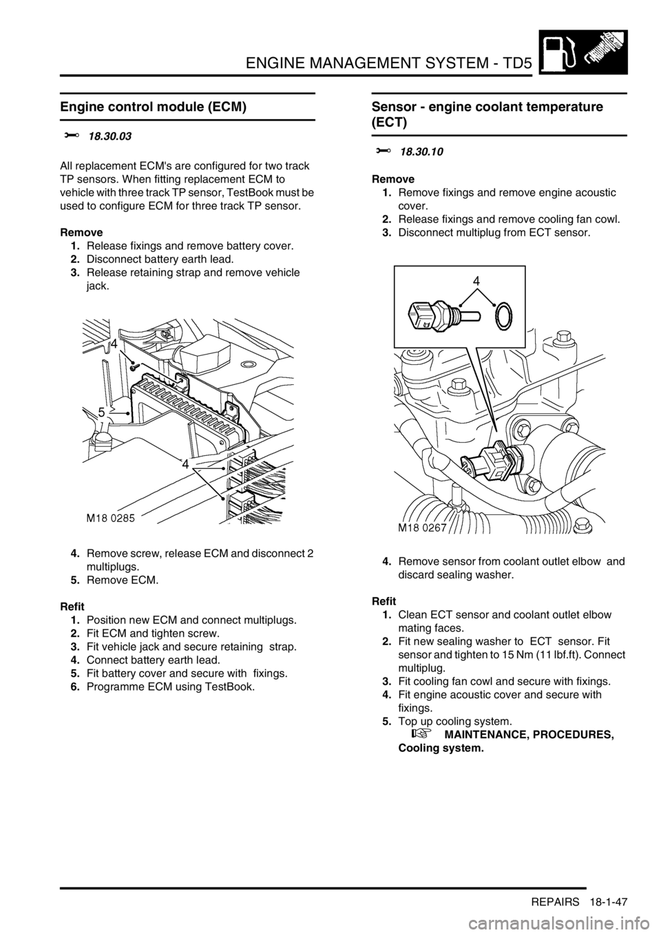
Engine control module (ECM)
$% 18.30.03
All replacement ECM's are configured for two track
TP sensors. When fitting replacement ECM to
vehicle with three track TP sensor, TestBook must be
used to configure ECM for three track TP sensor.
Remove
1.Release fixings and remove battery cover.
2.Disconnect battery earth lead.
3.Release retaining strap and remove vehicle
jack.
4.Remove screw, release ECM and disconnect 2
multiplugs.
5.Remove ECM.
Refit
1.Position new ECM and connect multiplugs.
2.Fit ECM and tighten screw.
3.Fit vehicle jack and secure retaining strap.
4.Connect battery earth lead.
5.Fit battery cover and secure with fixings.
6.Programme ECM using TestBook.
Sensor - engine coolant temperature
(ECT)
$% 18.30.10
Remove
1.Remove fixings and remove engine acoustic
cover.
2.Release fixings and remove cooling fan cowl.
3.Disconnect multiplug from ECT sensor.
4.Remove sensor from coolant outlet elbow and
discard sealing washer.
Refit
1.Clean ECT sensor and coolant outlet elbow
mating faces.
2.Fit new sealing washer to ECT sensor. Fit
sensor and tighten to 15 Nm (11 lbf.ft). Connect
multiplug.
3.Fit cooling fan cowl and secure with fixings.
4.Fit engine acoustic cover and secure with
fixings.
5.Top up cooling system.
+ MAINTENANCE, PROCEDURES,
Cooling system.
Page 441 of 1672

ENGINE MANAGEMENT SYSTEM - TD5
18-1-48 REPAIRS
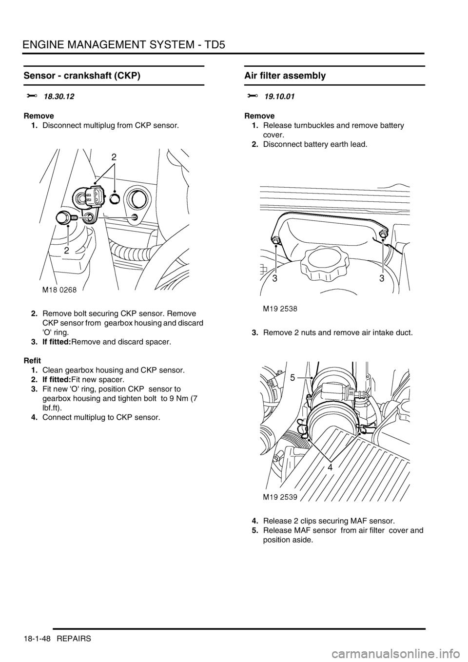
Sensor - crankshaft (CKP)
$% 18.30.12
Remove
1.Disconnect multiplug from CKP sensor.
2.Remove bolt securing CKP sensor. Remove
CKP sensor from gearbox housing and discard
'O' ring.
3. If fitted:Remove and discard spacer.
Refit
1.Clean gearbox housing and CKP sensor.
2. If fitted:Fit new spacer.
3.Fit new 'O' ring, position CKP sensor to
gearbox housing and tighten bolt to 9 Nm (7
lbf.ft).
4.Connect multiplug to CKP sensor.
Air filter assembly
$% 19.10.01
Remove
1.Release turnbuckles and remove battery
cover.
2.Disconnect battery earth lead.
3.Remove 2 nuts and remove air intake duct.
4.Release 2 clips securing MAF sensor.
5.Release MAF sensor from air filter cover and
position aside.
Page 442 of 1672

ENGINE MANAGEMENT SYSTEM - TD5
REPAIRS 18-1-49
6.Release air filter from 3 grommets, remove
assembly and discard 'O' ring.
7.Remove 2 screws, remove AAP sensor and
discard 'O' ring.
Refit
1.Clean MAF sensor and air filter mating faces.
2.Fit new 'O' ring to air filter.
3.Clean AAP sensor.
4.Using new 'O' ring, fit AAP sensor and tighten
screws.
5.Position air filter assembly and secure in
grommets.
6.Position MAF sensor and secure clips.
7.Position intake duct to air filter and tighten nuts.
8.Connect battery earth lead.
9.Fit battery cover and secure with fixings.
Element - air filter
$% 19.10.10
Remove
1.Release 2 clips and disconnect MAF sensor
from air filter cover.
Page 443 of 1672

ENGINE MANAGEMENT SYSTEM - TD5
18-1-50 REPAIRS
2.Disconnect multiplug from AAP sensor.
3.Release 2 clips and remove cover from air
filter.
4.Remove air filter element.
Refit
1.Clean air filter body and cover.
2.Fit new air filter element.
3.Position air cleaner cover and secure clips.
4.Position MAF sensor and secure clips.
5.Connect multiplug to AAP sensor.
Sensor - fuel temperature
$% 19.22.08
Remove
1.Remove 3 bolts and remove engine acoustic
cover.
2.Release fixings and remove battery cover.
3.Disconnect battery earth lead.
4.Disconnect multiplug from fuel temperature
sensor.
5. Thoroughly clean area around fuel
temperature sensor before removal.
6.Remove fuel temperature sensor and discard
sealing washer.
Refit
1.Clean fuel temperature sensor mating faces.
2.Fit new sealing washer and tighten fuel
temperature sensor to 13 Nm (10 lbf.ft) .
3.Connect multiplug to fuel temperature sensor.
4.Connect battery earth lead.
5.Fit battery cover and secure fixings.
6.Fit engine acoustic cover, and secure with
fixings.