LAND ROVER DISCOVERY 2002 Workshop Manual
Manufacturer: LAND ROVER, Model Year: 2002, Model line: DISCOVERY, Model: LAND ROVER DISCOVERY 2002Pages: 1672, PDF Size: 46.1 MB
Page 1621 of 1672

NAVIGATION SYSTEM
87-6 DESCRIPTION AND OPERATION
Service Menu
The service menu provides access to details of the navigation computer hardware and software, and can be accessed
when the navigation computer is in radio mode, by simultaneously pressing the NAV button and the 10 multifunction
buttons. The following items can then be scrolled through by pressing the Nxt (next) and Prv (previous) multifunction
buttons, or turning the RH rotary control:
lModel No.
lSerial No.
lChanger Reset
lGAL
lRadio Software
lRadio Bolo
lNavi Rom
lNavi Flash
lRTC Value
When Changer Reset is displayed, the CD autochanger (where fitted) can be reset by pressing the appropriate
multifunction button.
When the End multifunction button is pressed, the navigation computer quits the service menu and returns to radio
mode.
Garage Menu
Garage menu enables the navigation system to be tested and calibrated, and also contains a route navigation
demonstration. The garage menu is entered from the main navigation menu, as follows:
1Press the Nav button to access the system settings.
2Press and hold multifunction button 3, then press multifunction button 5 to display the garage menu.
The garage menu contains the following, which can be accessed using the RH rotary control:
lCALIBRATION RIDE – Used to calibrate the navigation computer, to enable route navigation.
lGPS INFO– Provides functional test of antenna by checking GPS reception. If functioning correctly, displays the
number of satellites being received, the date, time (Greenwich Mean Time) and the type of positional fix currently
possible.
lCALIBRATION– Allows vehicle specific calibration data to be entered, e.g. tyre size. Also allows current
calibration to be deleted prior to re-calibrating.
NOTE: Only known calibration data should be entered. The navigation computer cannot make route
calculations if incorrect data is entered.
lSENSORS– Allows wheel speed, reverse gear and gyro sensor inputs to be checked.
lVERSION– Displays navigation computer hardware and software details.
lSPEECH TEST– Performs a test of the navigation computer audio output.
lMODULE TEST– Performs a test routine on the internal components of the navigation computer.
lDEMO – Allows a route navigation demonstration to be run.
To quit the garage menu, press the Nav button.
Calibration
Calibration is required after initial installation or replacement of the navigation computer. It may also be necessary
after repairs to system wiring and if route navigation becomes inaccurate or fails to operate. If the navigation computer
contains an existing calibration, this must be deleted, using the garage menu, prior to running the new calibration
routine. The sensor inputs should also be checked before running the calibration routine.
Page 1622 of 1672

NAVIGATION SYSTEM
DESCRIPTION AND OPERATION 87-7
Sensor Check
1Call up the SENSORS screen on the LCD:
lIf the navigation CD-ROM has not been installed before, press and hold multifunction button 1 then press
multifunction button 10.
lIf the navigation CD-ROM has been installed before, use the garage menu as detailed above.
2Drive the vehicle forwards a short distance at a speed greater than 2.5 mph (4 km/h) and ensure the road speed
counter on the SENSORS screen starts to increment.
3Select reverse gear and ensure the direction arrows on the SENSORS screen point rearwards.
4Ensure the GPS data on the SENSORS screen is displayed and updated.
NOTE: The GPS data will randomly display a GPS MODULE FAILURE message. This is not a fault condition, and
no action need be taken, provided the GPS data switches between the GPS MODULE FAILURE message and
actual GPS data.
5Exit the SENSORS screen:
lIf the navigation CD-ROM has not been installed before, press and hold multifunction button 1 then press
multifunction button 10.
lIf the navigation CD-ROM has been installed before, press the Nav button.
Calibration Routine
1Park the vehicle outside in an area clear of high buildings, trees etc.
NOTE: The more open the surrounding area is, the faster the system will acquire sufficient GPS satellite signals to
begin calibration. To minimise the calibration time, the vehicle should not be moved again until the calibration
ride.
2Turn the ignition switch to position II. If the navigation computer does not come on, press the navigation
computer ON button.
3If necessary, use the navigation computer multifunction buttons to enter the security code.
4Turn the ignition switch to position 0 and remove the ignition key.
5Press the navigation computer ON button.
6Call up the SENSORS screen on the LCD:
lIf the navigation CD-ROM has not been installed before, press and hold multifunction button 1 then press
multifunction button 10.
lIf the navigation CD-ROM has been installed before, use the garage menu as detailed above.
7Turn the LH rotary control to minimum volume.
8Wait for 30 minutes. If necessary, the vehicle can be left unattended and locked.
NOTE: Land Rover recommend a minimum of 30 minutes be allowed to elapse in order to ensure that only a short
distance need be driven to achieve calibration.
9After the 30 minutes have elapsed, ensure the navigation computer LCD shows a GPS almanac figure of 27 or
higher.
10Start the vehicle engine and allow to idle.
11Install the navigation CD-ROM.
12Wait until the navigation computer LCD prompts for a language to be selected. Turn the RH rotary control to
scroll through the options, highlight the required language and press the RH rotary control to select.
13The navigation computer LCD will prompt for a voice to be selected. Turn the RH rotary control to scroll through
the options, highlight the required voice and press the RH rotary control to select.
14Wait until the navigation computer LCD advises "language has been loaded OK". Press the RH rotary control to
confirm the language and voice selections.
15The navigation computer LCD will default to the CALIBRATION RIDE screen and should show the
CALIBRATION RIDE CAN START message. The GPS data and the road speed counter will also be shown.
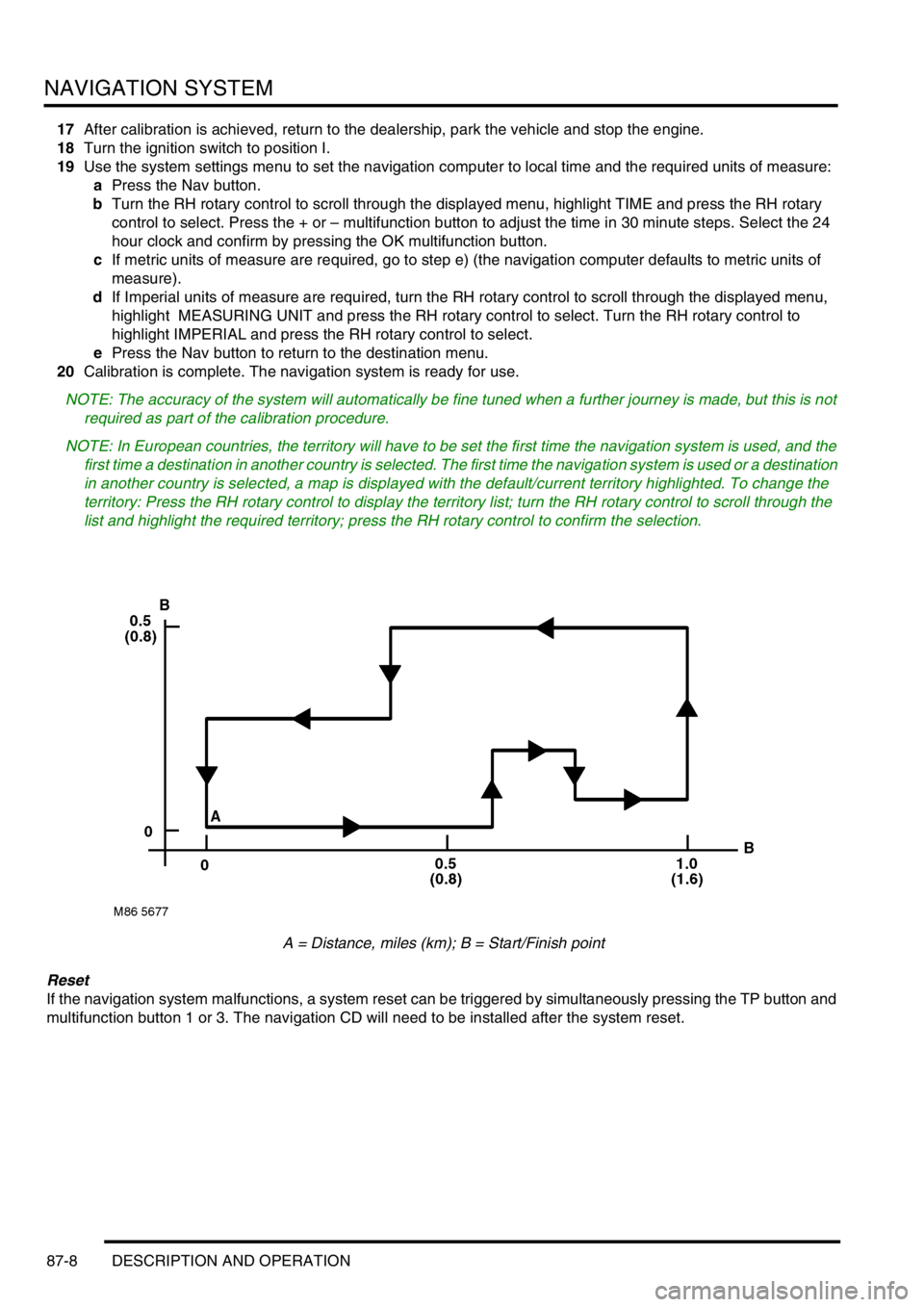
16Drive the vehicle over a road route approximating that shown below (it is not necessary to copy the route
exactly). Calibration is complete when the navigation computer LCD switches to show DESTINATION & POI
and the satellite graphic. If all the pre calibration ride conditions were complied with, calibration is typically
achieved within 3 miles (5 km) and usually occurs when the vehicle returns to the start point. However,
calibration may be achieved earlier in the journey and, if it is, there is no need to complete the remainder of the
calibration route.
Page 1623 of 1672

NAVIGATION SYSTEM
87-8 DESCRIPTION AND OPERATION
17After calibration is achieved, return to the dealership, park the vehicle and stop the engine.
18Turn the ignition switch to position I.
19Use the system settings menu to set the navigation computer to local time and the required units of measure:
aPress the Nav button.
bTurn the RH rotary control to scroll through the displayed menu, highlight TIME and press the RH rotary
control to select. Press the + or – multifunction button to adjust the time in 30 minute steps. Select the 24
hour clock and confirm by pressing the OK multifunction button.
cIf metric units of measure are required, go to step e) (the navigation computer defaults to metric units of
measure).
dIf Imperial units of measure are required, turn the RH rotary control to scroll through the displayed menu,
highlight MEASURING UNIT and press the RH rotary control to select. Turn the RH rotary control to
highlight IMPERIAL and press the RH rotary control to select.
ePress the Nav button to return to the destination menu.
20Calibration is complete. The navigation system is ready for use.
NOTE: The accuracy of the system will automatically be fine tuned when a further journey is made, but this is not
required as part of the calibration procedure.
NOTE: In European countries, the territory will have to be set the first time the navigation system is used, and the
first time a destination in another country is selected. The first time the navigation system is used or a destination
in another country is selected, a map is displayed with the default/current territory highlighted. To change the
territory: Press the RH rotary control to display the territory list; turn the RH rotary control to scroll through the
list and highlight the required territory; press the RH rotary control to confirm the selection.
A = Distance, miles (km); B = Start/Finish point
Reset
If the navigation system malfunctions, a system reset can be triggered by simultaneously pressing the TP button and
multifunction button 1 or 3. The navigation CD will need to be installed after the system reset.
Page 1624 of 1672

NAVIGATION SYSTEM
DESCRIPTION AND OPERATION 87-9
Steering Wheel Switches
The steering wheel switches provide remote control operation for some of the navigation computer functions. The
switches can be used to select between the radio/CD/navigation modes, to adjust the volume (in all modes) and to
select search/preset up/down for radio and CD operation.
Remote Control Interface Unit
The remote control interface unit converts the analogue signals from the steering wheel switches into digital signals
for use by the navigation computer. The remote control interface unit is installed in a bracket immediately below the
navigation computer.
The radio remote switches form a resistance ladder between two wires with the resistance across wires dependent
on which switch is pressed. The remote control interface unit monitors the two wires and converts their input into
Instrument (I) bus protocol messages, which it outputs on a dedicated serial link to the navigation computer.
Page 1625 of 1672

NAVIGATION SYSTEM
87-10 DESCRIPTION AND OPERATION
Page 1626 of 1672

NAVIGATION SYSTEM
REPAIRS 87-11
REPAIRS
Interface electronic control unit (ECU) -
remote control
$% 86.53.15
Remove
1.Remove navigation display unit.
+ NAVIGATION SYSTEM, REPAIRS,
Display unit.
2.Remove automatic temperature control unit.
+ AIR CONDITIONING, REPAIRS, ECU
- air temperature control.
3.Remove 2 nuts securing interface carrier
bracket, carefully pull bracket out of fascia.
4.Release interface ECU from bracket,
disconnect multiplug and remove ECU.Refit
1.Secure interface ECU in bracket and connect
multiplug.
2.Carefully position carrier bracket in fascia,
secure with nuts and tighten to 10 Nm (7 lbf.ft).
3.Fit automatic temperature control unit.
+ AIR CONDITIONING, REPAIRS, ECU
- air temperature control.
4.Fit navigation display unit.
+ NAVIGATION SYSTEM, REPAIRS,
Display unit.
M86 5760
M86 5762
Page 1627 of 1672

NAVIGATION SYSTEM
87-12 REPAIRS
Display unit
$% 86.53.20
Remove
1.Fit tool LRT-86-009 into slots ensuring correct
handed key is in correct slot.
The tools are stamped either 'TOP L' or 'TOP
R', ensure the stamping is facing upwards
when removing the unit.
2.Pull display unit from fascia.
3.Disconnect 3 multiplugs and 2 coax cables
from display unit and remove unit.
4.Push display unit retaining clips inwards and
remove keys.Refit
1.Position display unit to fascia, connect
multiplugs and coax cables.
2.Push display unit into fascia until retaining clips
engage.
3.Enter security code and check system is
operational.
M86 5824
M86 5825
Page 1628 of 1672

INSTRUMENTS
DESCRIPTION AND OPERATION 88-1
INS TRUMENTS DESCRIPTION AND OPERAT ION
Instrument pack
1Hill descent control information warning lamp
2Overspeed warning lamp
3Brake system warning lamp
4Malfunction Indicator Lamp (MIL)
5Tachometer
6Direction indicator warning lamp
7Main beam warning lamp
8Direction indicator warning lamp
9Speedometer
10SRS warning lamp
11Off road mode warning lamp
12Glow plug warning lamp
13Trailer warning lamp
14Water in fuel filter warning lamp
15Transmission high temperature warning lamp
16Seat belt warning lamp17Fuel tank level gauge
18Low fuel level warning lamp
19LCD odometer/trip meter
20Anti-theft status warning lamp
21ABS warning lamp
22Gearbox manual/sport mode warning lamp
23Alternator charge warning lamp
24ACE warning lamp
25Oil pressure warning lamp
26SLS warning lamp
27Hill descent control warning lamp
28Engine coolant temperature gauge
29High coolant temperature warning lamp
30Traction control warning lamp
31Differential lock warning lamp
32Transfer box neutral warning lamp
Page 1629 of 1672

INSTRUMENTS
88-2 DESCRIPTION AND OPERATION
Instrument component location - Engine
compartment / underneath vehicle
1ECM (diesel models)
2Alternator
3Glow plugs
4Transmission temperature sensor
5Water in fuel filter sensor
6Fuel tank sender unit
7Differential lock switch – vehicles up to 03
model year8Differential lock switches – vehicles from 03
model year (where fitted)
9Parking brake switch
10Brake fluid level switch
11Oil pressure switch
Page 1630 of 1672

INSTRUMENTS
DESCRIPTION AND OPERATION 88-3
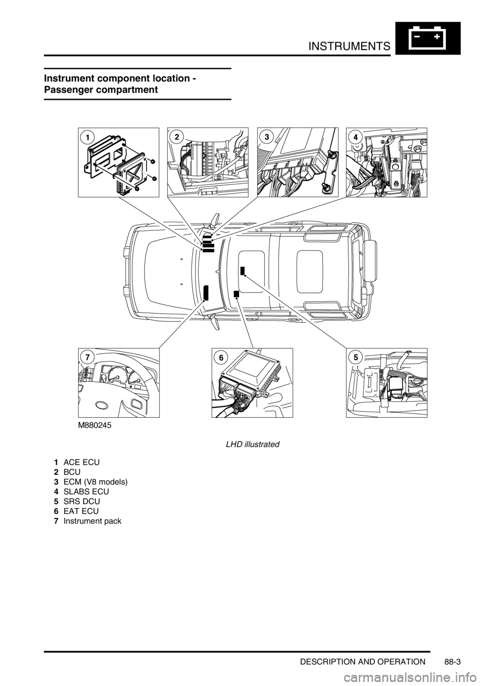
Instrument component location -
Passenger compartment
LHD illustrated
1ACE ECU
2BCU
3ECM (V8 models)
4SLABS ECU
5SRS DCU
6EAT ECU
7Instrument pack