fuse box LAND ROVER DISCOVERY 2002 User Guide
[x] Cancel search | Manufacturer: LAND ROVER, Model Year: 2002, Model line: DISCOVERY, Model: LAND ROVER DISCOVERY 2002Pages: 1672, PDF Size: 46.1 MB
Page 361 of 1672
EMISSION CONTROL - V8
17-2-24 DESCRIPTION AND OPERATION
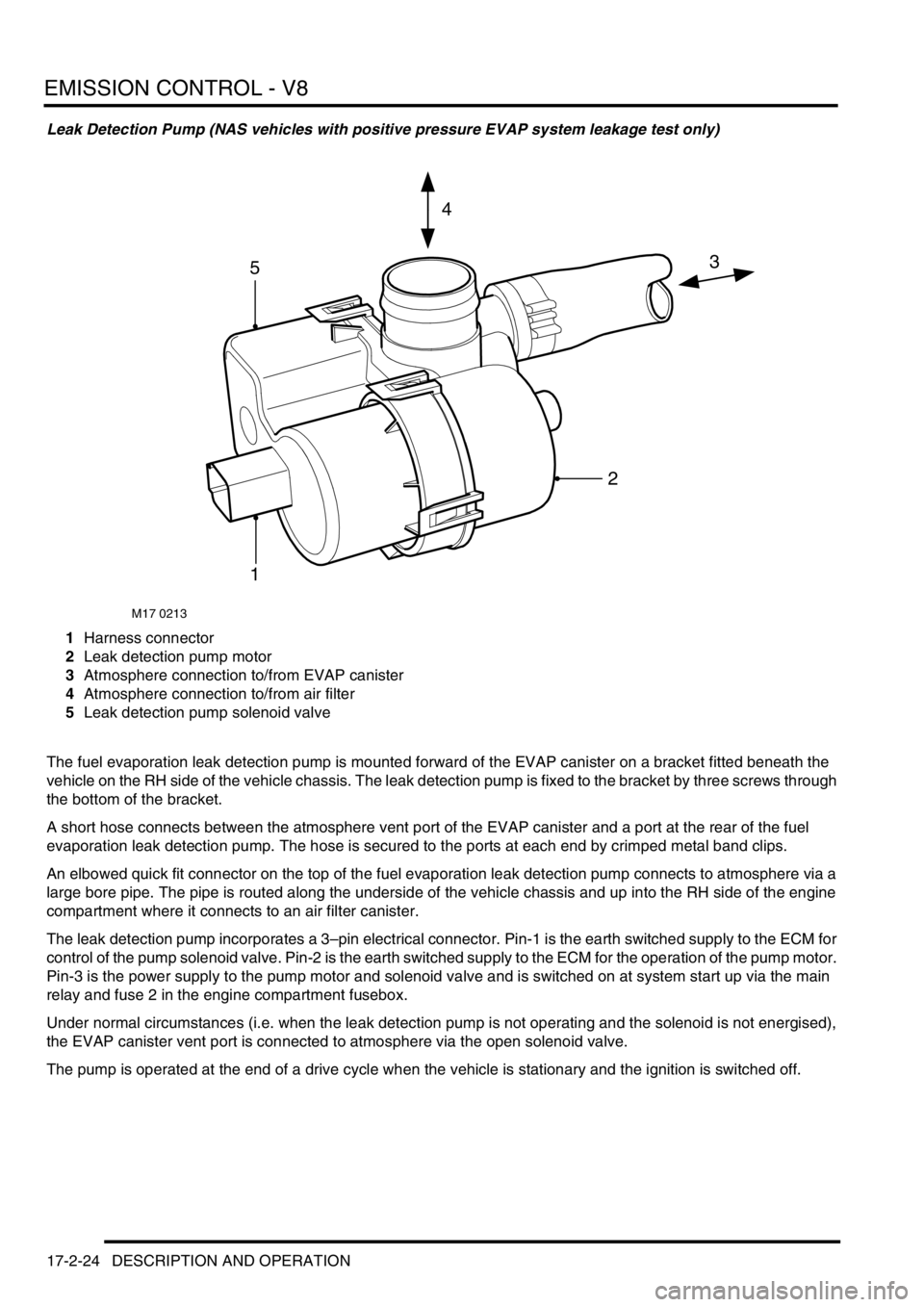
Leak Detection Pump (NAS vehicles with positive pressure EVAP system leakage test only)
1Harness connector
2Leak detection pump motor
3Atmosphere connection to/from EVAP canister
4Atmosphere connection to/from air filter
5Leak detection pump solenoid valve
The fuel evaporation leak detection pump is mounted forward of the EVAP canister on a bracket fitted beneath the
vehicle on the RH side of the vehicle chassis. The leak detection pump is fixed to the bracket by three screws through
the bottom of the bracket.
A short hose connects between the atmosphere vent port of the EVAP canister and a port at the rear of the fuel
evaporation leak detection pump. The hose is secured to the ports at each end by crimped metal band clips.
An elbowed quick fit connector on the top of the fuel evaporation leak detection pump connects to atmosphere via a
large bore pipe. The pipe is routed along the underside of the vehicle chassis and up into the RH side of the engine
compartment where it connects to an air filter canister.
The leak detection pump incorporates a 3–pin electrical connector. Pin-1 is the earth switched supply to the ECM for
control of the pump solenoid valve. Pin-2 is the earth switched supply to the ECM for the operation of the pump motor.
Pin-3 is the power supply to the pump motor and solenoid valve and is switched on at system start up via the main
relay and fuse 2 in the engine compartment fusebox.
Under normal circumstances (i.e. when the leak detection pump is not operating and the solenoid is not energised),
the EVAP canister vent port is connected to atmosphere via the open solenoid valve.
The pump is operated at the end of a drive cycle when the vehicle is stationary and the ignition is switched off.
M17 0213
3
4
5
1
2
Page 365 of 1672

EMISSION CONTROL - V8
17-2-28 DESCRIPTION AND OPERATION
The SAI pump is attached to a bracket at the rear RH side of the engine compartment and is fixed to the bracket by
three studs and nuts. The pump is electrically powered from a 12V battery supply via a dedicated relay and supplies
approximately 35kg/hr of air when the vehicle is at idle in Neutral/Park on a start from 20
°C (68°F).
Air is drawn into the pump through vents in its front cover and is then passed through a foam filter to remove
particulates before air injection. The air is delivered to the exhaust manifold on each side of the engine through a
combination of plastic and metal pipes.
The air delivery pipe is a flexible plastic type, and is connected to the air pump outlet via a plastic quick-fit connector.
The other end of the flexible plastic pipe connects to the fixed metal pipework via a short rubber hose. The part of the
flexible plastic pipe which is most vulnerable to engine generated heat is protected by heat reflective sleeving. The
metal delivery pipe has a fabricated T-piece included where the pressurised air is split for delivery to each exhaust
manifold via the SAI control valves.
The pipes from the T-piece to each of the SAI control valves are approximately the same length, so that the pressure
and mass of the air delivered to each bank will be equal. The ends of the pipes are connected to the inlet port of each
SAI control valve through short rubber hose connections.
The T-piece is mounted at the rear of the engine (by the ignition coils) and features a welded mounting bracket which
is fixed to the engine by two studs and nuts.
The foam filter in the air intake of the SAI pump provides noise reduction and protects the pump from damage due to
particulate contamination. In addition, the pump is fitted on rubber mountings to help prevent noise which is generated
by pump operation from being transmitted through the vehicle body into the passenger compartment.
If the secondary air injection pump malfunctions, the following fault codes may be stored in the ECM diagnostic
memory, which can be retrieved using 'Testbook':
Secondary air injection (SAI) pump relay
The secondary air injection pump relay is located in the engine compartment fusebox. The engine control module
(ECM) is used to control the operation of the SAI pump via the SAI pump relay. Power to the coil of the relay is supplied
from the vehicle battery via the main relay and the ground connection to the coil is via the ECM.
Power to the SAI pump relay contacts is via fusible link FL2 which is located in the engine compartment fusebox.
P-code Description
P0418Secondary air injection pump powerstage fault (e.g. - SAI pump relay fault / SAI
pump or relay not connected / open circuit / harness damage).
Page 367 of 1672
EMISSION CONTROL - V8
17-2-30 DESCRIPTION AND OPERATION
Electrical connection to the SAI vacuum solenoid valve is via a 2–pin connector. A 12V electrical power supply to the
SAI vacuum solenoid valve is provided via the Main relay and Fuse 2 in the engine compartment fusebox. The ground
connection is via the ECM which controls the SAI vacuum solenoid valve operation. Note that the harness
connector to the SAI solenoid valve is grey, and must not be confused with the harness connector to the
EVAP system purge valve which is black.
The ECM switches on the SAI vacuum solenoid valve at the same time as initiating SAI pump operation. When the
SAI vacuum solenoid valve is open, a steady vacuum supply is allowed through to open the two vacuum operated
SAI control valves. When the ECM breaks the earth path to the SAI vacuum solenoid valve, the valve closes and
immediately shuts off the vacuum supply to the two SAI control valves at the same time as the SAI pump operation
is terminated.
If the SAI vacuum solenoid valve malfunctions, the following fault codes may be stored in the ECM diagnostic
memory, which can be retrieved using 'Testbook':
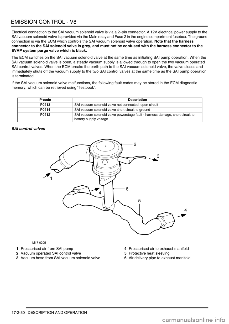
SAI control valves
1Pressurised air from SAI pump
2Vacuum operated SAI control valve
3Vacuum hose from SAI vacuum solenoid valve4Pressurised air to exhaust manifold
5Protective heat sleeving
6Air delivery pipe to exhaust manifold
P-code Description
P0413SAI vacuum solenoid valve not connected, open circuit
P0414SAI vacuum solenoid valve short circuit to ground
P0412SAI vacuum solenoid valve powerstage fault - harness damage, short circuit to
battery supply voltage
M17 0205
1
3
4
4
2
6
5
Page 379 of 1672

EMISSION CONTROL - V8
17-2-42 DESCRIPTION AND OPERATION
Secondary air injection system
When the engine is started, the engine control module checks the engine coolant temperature and if it is below 55°
C, the ECM grounds the electrical connection to the coil of the secondary air injection (SAI) pump relay.
A 12V battery supply is fed to the inertia switch via fuse 13 in the engine compartment fusebox. When the inertia
switch contacts are closed, the feed passes through the switch and is connected to the coil of the Main relay. An earth
connection from the Main relay coil is connected to the ECM. When the ECM completes the earth path, the coil
energises and closes the contacts of the Main relay.
The Main and Secondary Air Injection (SAI) pump relays are located in the engine compartment fusebox. When the
contacts of the Main relay are closed, a 12V battery supply is fed to the coil of the SAI pump relay. An earth connection
from the coil of the SAI pump relay is connected to the ECM. When the ECM completes the earth path, the coil
energises and closes the contacts of the SAI pump relay to supply 12V to the SAI pump via fusible link 2 in the engine
compartment fusebox. The SAI pump starts to operate, and will continue to do so until the ECM switches off the earth
connection to the coil of the SAI pump relay.
The SAI pump remains operational for a period determined by the ECM and depends on the starting temperature of
the engine, or for a maximum operation period determined by the ECM if the target engine coolant temperature has
not been reached in the usual time.
When the contacts of the main relay are closed, a 12V battery supply is fed to the SAI solenoid valve via Fuse 2 in
the engine compartment fusebox.
The ECM grounds the electrical connection to the SAI vacuum solenoid valve at the same time as it switches on the
SAI pump motor. When the SAI vacuum solenoid valve is energised, a vacuum is provided to the operation control
ports on both of the vacuum operated SAI control valves at the exhaust manifolds. The control vacuum is sourced
from the intake manifold depression and routed to the SAI control valves via a vacuum reservoir and the SAI vacuum
solenoid valve.
The vacuum reservoir is included in the vacuum supply circuit to prevent vacuum fluctuations caused by changes in
the intake manifold depression affecting the operation of the SAI control valves.
When a vacuum is applied to the control ports of the SAI control valves, the valves open to allow pressurised air from
the SAI pump to pass through to the exhaust ports in the cylinder heads for combustion.
When the ECM has determined that the SAI pump has operated for the desired duration, it switches off the earth paths
to the SAI pump relay and the SAI vacuum solenoid valve. With the SAI vacuum solenoid valve de-energised, the
valve closes, cutting off the vacuum supply to the SAI control valves. The SAI control valves close immediately and
completely to prevent any further pressurised air from the SAI pump entering the exhaust manifolds.
The engine coolant temperature sensor incurs a time lag in respect of detecting a change in temperature and the SAI
pump automatically enters a 'soak period' between operations to prevent the SAI pump overheating. The ECM also
compares the switch off and start up temperatures, to determine whether it is necessary to operate the SAI pump.
This prevents the pump running repeatedly and overheating on repeat starts.
Other factors which may prevent or stop SAI pump operation include the prevailing engine speed / load conditions.
Page 403 of 1672
ENGINE MANAGEMENT SYSTEM - TD5
18-1-10 DESCRIPTION AND OPERATION
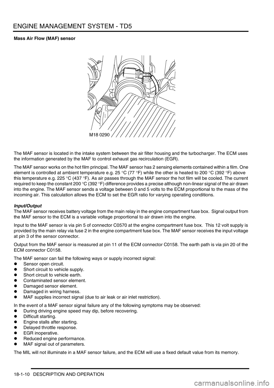
Mass Air Flow (MAF) sensor
The MAF sensor is located in the intake system between the air filter housing and the turbocharger. The ECM uses
the information generated by the MAF to control exhaust gas recirculation (EGR).
The MAF sensor works on the hot film principal. The MAF sensor has 2 sensing elements contained within a film. One
element is controlled at ambient temperature e.g. 25
°C (77 °F) while the other is heated to 200 °C (392 °F) above
this temperature e.g. 225
°C (437 °F). As air passes through the MAF sensor the hot film will be cooled. The current
required to keep the constant 200
°C (392 °F) difference provides a precise although non-linear signal of the air drawn
into the engine. The MAF sensor sends a voltage between 0 and 5 volts to the ECM proportional to the mass of the
incoming air. This calculation allows the ECM to set the EGR ratio for varying operating conditions.
Input/Output
The MAF sensor receives battery voltage from the main relay in the engine compartment fuse box. Signal output from
the MAF sensor to the ECM is a variable voltage proportional to air drawn into the engine.
Input to the MAF sensor is via pin 5 of connector C0570 at the engine compartment fuse box. This 12 volt supply is
provided by the main relay via fuse 2 in the engine compartment fuse box. The MAF sensor receives the input voltage
at pin 3 of the sensor connector.
Output from the MAF sensor is measured at pin 11 of the ECM connector C0158. The earth path is via pin 20 of the
ECM connector C0158.
The MAF sensor can fail the following ways or supply incorrect signal:
lSensor open circuit.
lShort circuit to vehicle supply.
lShort circuit to vehicle earth.
lContaminated sensor element.
lDamaged sensor element.
lDamaged in wiring harness.
lMAF supplies incorrect signal (due to air leak or air inlet restriction).
In the event of a MAF sensor signal failure any of the following symptoms may be observed:
lDuring driving engine speed may dip, before recovering.
lDifficult starting.
lEngine stalls after starting.
lDelayed throttle response.
lEGR inoperative.
lReduced engine performance.
lMAF signal out of parameters.
The MIL will not illuminate in a MAF sensor failure, and the ECM will use a fixed default value from its memory.
Page 417 of 1672
ENGINE MANAGEMENT SYSTEM - TD5
18-1-24 DESCRIPTION AND OPERATION
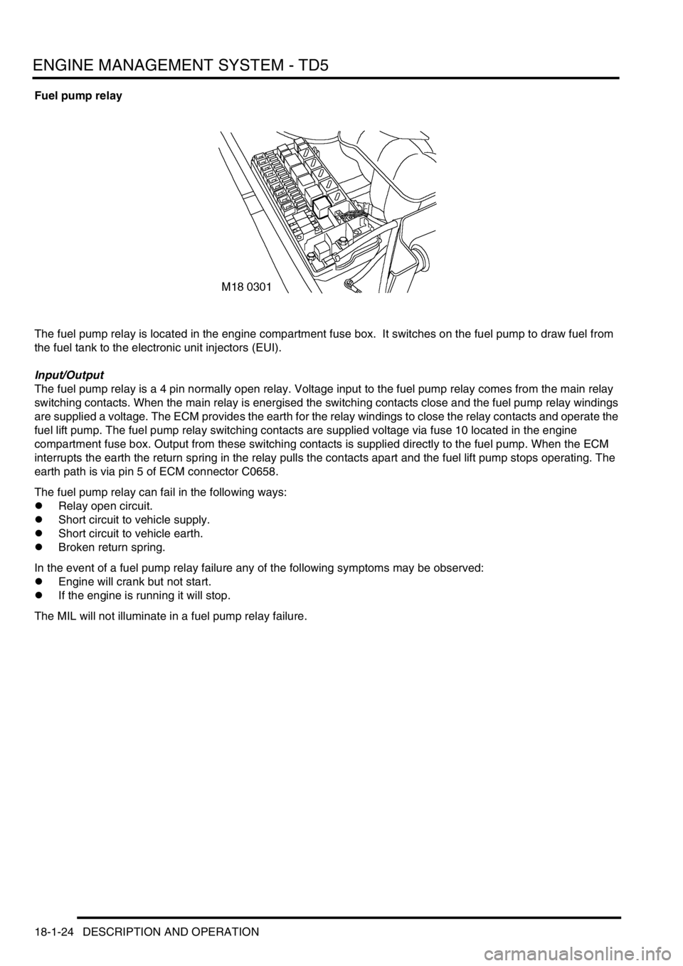
Fuel pump relay
The fuel pump relay is located in the engine compartment fuse box. It switches on the fuel pump to draw fuel from
the fuel tank to the electronic unit injectors (EUI).
Input/Output
The fuel pump relay is a 4 pin normally open relay. Voltage input to the fuel pump relay comes from the main relay
switching contacts. When the main relay is energised the switching contacts close and the fuel pump relay windings
are supplied a voltage. The ECM provides the earth for the relay windings to close the relay contacts and operate the
fuel lift pump. The fuel pump relay switching contacts are supplied voltage via fuse 10 located in the engine
compartment fuse box. Output from these switching contacts is supplied directly to the fuel pump. When the ECM
interrupts the earth the return spring in the relay pulls the contacts apart and the fuel lift pump stops operating. The
earth path is via pin 5 of ECM connector C0658.
The fuel pump relay can fail in the following ways:
lRelay open circuit.
lShort circuit to vehicle supply.
lShort circuit to vehicle earth.
lBroken return spring.
In the event of a fuel pump relay failure any of the following symptoms may be observed:
lEngine will crank but not start.
lIf the engine is running it will stop.
The MIL will not illuminate in a fuel pump relay failure.
Page 418 of 1672
ENGINE MANAGEMENT SYSTEM - TD5
DESCRIPTION AND OPERATION 18-1-25
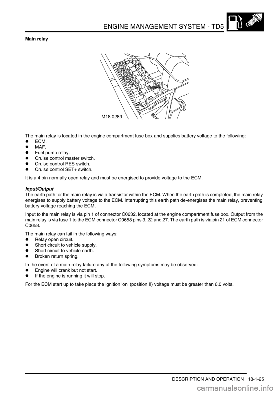
Main relay
The main relay is located in the engine compartment fuse box and supplies battery voltage to the following:
lECM.
lMAF.
lFuel pump relay.
lCruise control master switch.
lCruise control RES switch.
lCruise control SET+ switch.
It is a 4 pin normally open relay and must be energised to provide voltage to the ECM.
Input/Output
The earth path for the main relay is via a transistor within the ECM. When the earth path is completed, the main relay
energises to supply battery voltage to the ECM. Interrupting this earth path de-energises the main relay, preventing
battery voltage reaching the ECM.
Input to the main relay is via pin 1 of connector C0632, located at the engine compartment fuse box. Output from the
main relay is via fuse 1 to the ECM connector C0658 pins 3, 22 and 27. The earth path is via pin 21 of ECM connector
C0658.
The main relay can fail in the following ways:
lRelay open circuit.
lShort circuit to vehicle supply.
lShort circuit to vehicle earth.
lBroken return spring.
In the event of a main relay failure any of the following symptoms may be observed:
lEngine will crank but not start.
lIf the engine is running it will stop.
For the ECM start up to take place the ignition 'on' (position II) voltage must be greater than 6.0 volts.
Page 421 of 1672
ENGINE MANAGEMENT SYSTEM - TD5
18-1-28 DESCRIPTION AND OPERATION
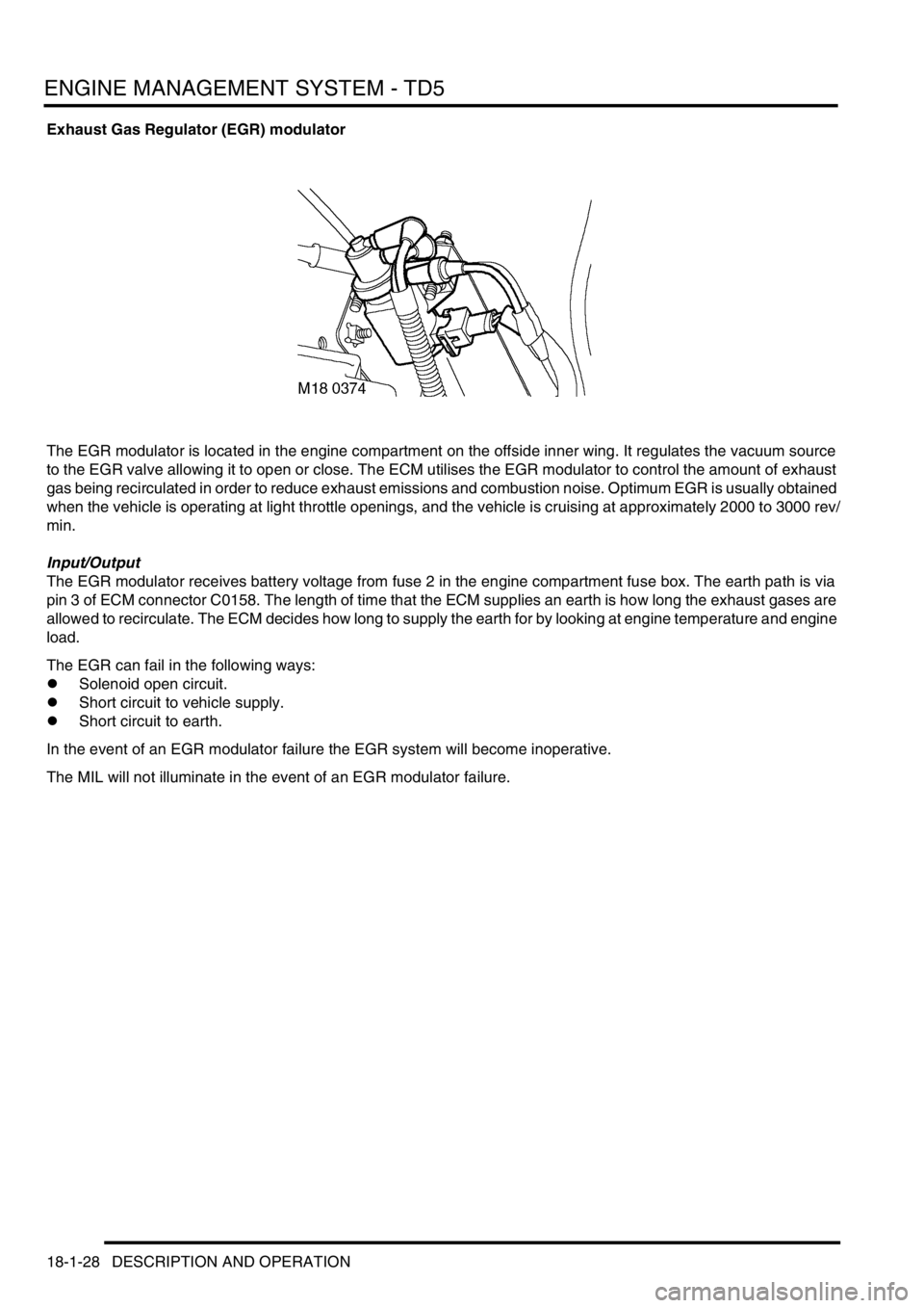
Exhaust Gas Regulator (EGR) modulator
The EGR modulator is located in the engine compartment on the offside inner wing. It regulates the vacuum source
to the EGR valve allowing it to open or close. The ECM utilises the EGR modulator to control the amount of exhaust
gas being recirculated in order to reduce exhaust emissions and combustion noise. Optimum EGR is usually obtained
when the vehicle is operating at light throttle openings, and the vehicle is cruising at approximately 2000 to 3000 rev/
min.
Input/Output
The EGR modulator receives battery voltage from fuse 2 in the engine compartment fuse box. The earth path is via
pin 3 of ECM connector C0158. The length of time that the ECM supplies an earth is how long the exhaust gases are
allowed to recirculate. The ECM decides how long to supply the earth for by looking at engine temperature and engine
load.
The EGR can fail in the following ways:
lSolenoid open circuit.
lShort circuit to vehicle supply.
lShort circuit to earth.
In the event of an EGR modulator failure the EGR system will become inoperative.
The MIL will not illuminate in the event of an EGR modulator failure.
Page 424 of 1672

ENGINE MANAGEMENT SYSTEM - TD5
DESCRIPTION AND OPERATION 18-1-31
The purpose of the glow plugs is:
lAssist cold engine start.
lReduce exhaust emissions at low engine load/speed.
The main part of the glow plug is a tubular heating element that protrudes into the combustion chamber of the engine.
The heating element contains a spiral filament that is encased in magnesium oxide powder. At the tip of the tubular
heating element is the heater coil. Behind the heater coil and connected in series is a control coil. The control coil
regulates the heater coil to ensure that it does not overheat and cause a possible failure. The glow plug circuit has its
own control relay located in the engine compartment fuse box.
Pre-heat is the length of time the glow plugs operate prior to engine cranking. The ECM controls the pre-heat time of
the glow plugs based on battery voltage and coolant temperature information via the glow plug relay.
Post-heat is the length of time the glow plugs operate after the engine starts. The ECM controls the post-heat time
based on ECT information. If the ECT fails the ECM will operate pre/post-heat time strategies with default values from
its memory. The engine will be difficult to start.
Input/Output
The glow plugs receive voltage from the glow plug relay that is controlled by the ECM. The ECM provides the earth
path for the relay coil closing the relay contacts and supplying the glow plugs with battery voltage. The supply voltage
heats the coils to approximately 1000
°C (1832 °F). The glow plug circuit is wired in parallel, the body of each glow
plug is screwed directly into the engine block which provides each glow plug with an earth path.
The glow plugs can fail in the following ways:
lHeater coil open circuit.
lControl coil open circuit.
lPoor earth quality.
lShort circuit to vehicle supply.
lShort circuit to vehicle earth.
lWiring loom fault.
lRelay windings open circuit.
lIncorrect relay fitted.
In the event of a glow plug failure any of the following symptoms may be observed:
lDifficult starting.
lExcessive smoke emissions after engine start.
Page 436 of 1672

ENGINE MANAGEMENT SYSTEM - TD5
DESCRIPTION AND OPERATION 18-1-43
Air Conditioning (A/C)
The ECM controls operation of the A/C compressor and the engine's electric cooling fan in response to requests from
the Automatic Temperature Control (ATC) ECU.
A/C request
When the ATC ECU supplies the ECM with an A/C request, the ECM energises the compressor clutch relay. The
compressor clutch relay is located in the engine compartment fuse box. It is a four pin normally open relay. This means
that the relay must be energised to drive the compressor clutch. During periods of high driver demand such as hard
acceleration or maximum rev/min the ECM will disable the compressor clutch for a short time. This is to reduce the
load on the engine.
The operation of the A/C request is via a switch being connected to earth. Voltage is supplied via pin 9 of connector
C0658 of the ECM, at the point at which the switch is pressed the connection to the earth path is made and the
compressor clutch is engaged.
The ECM provides the earth for the relay windings to allow the compressor clutch relay contacts to close and the
compressor clutch drive to receive battery voltage. The ECM uses a transistor as a switch to generate an open circuit
in the earth path of the relay windings. When the ECM closes down the earth path, the return spring in the relay will
pull the contacts apart to shut down the compressor clutch drive. Fuse 6, located in the engine compartment fuse box,
provides voltage to the compressor clutch relay switching contacts. The relay windings are supplied with battery
voltage from the main relay, also located in the engine compartment fuse box. The earth path for the relay windings
is via pin 29 of the ECM connector C0658. When the relay is energised the output from the switching contacts is
directly to the compressor clutch.
Cooling fan request
The A/C fan request is an input to the ECM from the ATC ECU to request that the engine's electric cooling fan is
activated to provide additional cooling for the A/C condenser.
The cooling fan relay is located in the engine compartment fuse box and is also controlled by the ECM. It is a four pin
normally open relay. This means that the relay must be energised to drive the cooling fan. The cooling fan is used
especially when the engine is operating at excessively high temperatures. It is also used as a part of the ECM backup
strategy if the ECT sensor fails.
The operation of the cooling fan request is via a switch being connected to earth. Voltage is supplied via pin 23 of
connector C0658 of the ECM, at the point at when the switch is pressed the connection to the earth path is made and
the cooling fan is engaged.
The ECM provides the earth for the cooling fan relay windings to allow the relay contacts to close and the cooling fan
motor to receive battery voltage. The ECM uses a transistor as a switch to generate an open circuit in the earth path
of the relay windings. When the ECM closes down the earth path, the return spring in the relay will pull the contacts
apart to shut down the cooling fan motor drive. Input to the A/C cooling fan relay switching contacts is via fuse 4
located in the engine compartment fuse box. The relay windings are supplied with battery voltage from the main relay,
also located in the engine compartment fuse box. The earth path for the relay windings is via pin 4 of the ECM
connector C0658. When the relay is energised the output from the switching contacts is directly to the cooling fan
motor.