light LAND ROVER DISCOVERY 2002 User Guide
[x] Cancel search | Manufacturer: LAND ROVER, Model Year: 2002, Model line: DISCOVERY, Model: LAND ROVER DISCOVERY 2002Pages: 1672, PDF Size: 46.1 MB
Page 45 of 1672
GENERAL INFORMATION
03-10
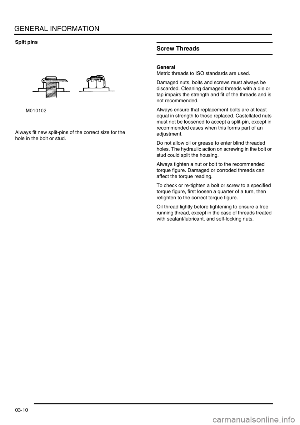
Split pins
Always fit new split-pins of the correct size for the
hole in the bolt or stud.
Screw Threads
General
Metric threads to ISO standards are used.
Damaged nuts, bolts and screws must always be
discarded. Cleaning damaged threads with a die or
tap impairs the strength and fit of the threads and is
not recommended.
Always ensure that replacement bolts are at least
equal in strength to those replaced. Castellated nuts
must not be loosened to accept a split-pin, except in
recommended cases when this forms part of an
adjustment.
Do not allow oil or grease to enter blind threaded
holes. The hydraulic action on screwing in the bolt or
stud could split the housing.
Always tighten a nut or bolt to the recommended
torque figure. Damaged or corroded threads can
affect the torque reading.
To check or re-tighten a bolt or screw to a specified
torque figure, first loosen a quarter of a turn, then
retighten to the correct torque figure.
Oil thread lightly before tightening to ensure a free
running thread, except in the case of threads treated
with sealant/lubricant, and self-locking nuts.
Page 47 of 1672
GENERAL INFORMATION
03-12
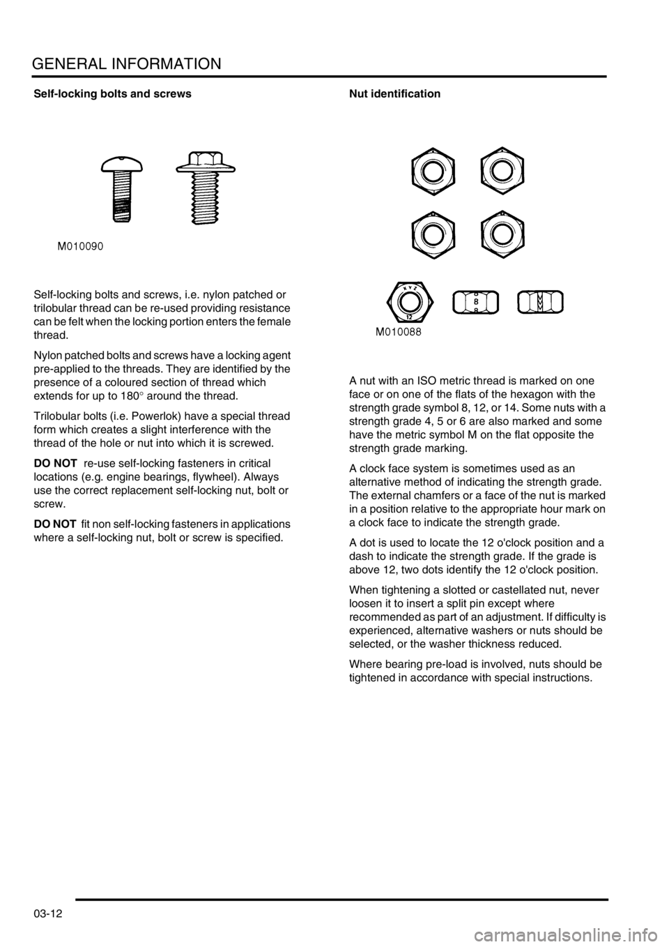
Self-locking bolts and screws
Self-locking bolts and screws, i.e. nylon patched or
trilobular thread can be re-used providing resistance
can be felt when the locking portion enters the female
thread.
Nylon patched bolts and screws have a locking agent
pre-applied to the threads. They are identified by the
presence of a coloured section of thread which
extends for up to 180
° around the thread.
Trilobular bolts (i.e. Powerlok) have a special thread
form which creates a slight interference with the
thread of the hole or nut into which it is screwed.
DO NOT re-use self-locking fasteners in critical
locations (e.g. engine bearings, flywheel). Always
use the correct replacement self-locking nut, bolt or
screw.
DO NOT fit non self-locking fasteners in applications
where a self-locking nut, bolt or screw is specified.Nut identification
A nut with an ISO metric thread is marked on one
face or on one of the flats of the hexagon with the
strength grade symbol 8, 12, or 14. Some nuts with a
strength grade 4, 5 or 6 are also marked and some
have the metric symbol M on the flat opposite the
strength grade marking.
A clock face system is sometimes used as an
alternative method of indicating the strength grade.
The external chamfers or a face of the nut is marked
in a position relative to the appropriate hour mark on
a clock face to indicate the strength grade.
A dot is used to locate the 12 o'clock position and a
dash to indicate the strength grade. If the grade is
above 12, two dots identify the 12 o'clock position.
When tightening a slotted or castellated nut, never
loosen it to insert a split pin except where
recommended as part of an adjustment. If difficulty is
experienced, alternative washers or nuts should be
selected, or the washer thickness reduced.
Where bearing pre-load is involved, nuts should be
tightened in accordance with special instructions.
Page 50 of 1672
GENERAL INFORMATION
03-15
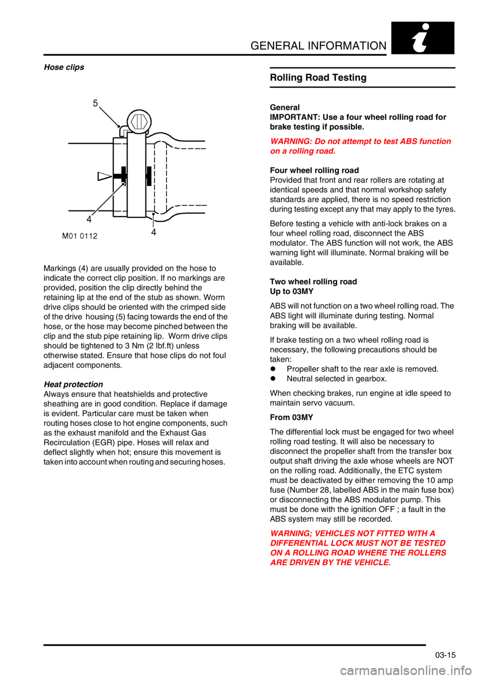
Hose clips
Markings (4) are usually provided on the hose to
indicate the correct clip position. If no markings are
provided, position the clip directly behind the
retaining lip at the end of the stub as shown. Worm
drive clips should be oriented with the crimped side
of the drive housing (5) facing towards the end of the
hose, or the hose may become pinched between the
clip and the stub pipe retaining lip. Worm drive clips
should be tightened to 3 Nm (2 lbf.ft) unless
otherwise stated. Ensure that hose clips do not foul
adjacent components.
Heat protection
Always ensure that heatshields and protective
sheathing are in good condition. Replace if damage
is evident. Particular care must be taken when
routing hoses close to hot engine components, such
as the exhaust manifold and the Exhaust Gas
Recirculation (EGR) pipe. Hoses will relax and
deflect slightly when hot; ensure this movement is
taken into account when routing and securing hoses.
Rolling Road Testing
General
IMPORTANT: Use a four wheel rolling road for
brake testing if possible.
WARNING: Do not attempt to test ABS function
on a rolling road.
Four wheel rolling road
Provided that front and rear rollers are rotating at
identical speeds and that normal workshop safety
standards are applied, there is no speed restriction
during testing except any that may apply to the tyres.
Before testing a vehicle with anti-lock brakes on a
four wheel rolling road, disconnect the ABS
modulator. The ABS function will not work, the ABS
warning light will illuminate. Normal braking will be
available.
Two wheel rolling road
Up to 03MY
ABS will not function on a two wheel rolling road. The
ABS light will illuminate during testing. Normal
braking will be available.
If brake testing on a two wheel rolling road is
necessary, the following precautions should be
taken:
lPropeller shaft to the rear axle is removed.
lNeutral selected in gearbox.
When checking brakes, run engine at idle speed to
maintain servo vacuum.
From 03MY
The differential lock must be engaged for two wheel
rolling road testing. It will also be necessary to
disconnect the propeller shaft from the transfer box
output shaft driving the axle whose wheels are NOT
on the rolling road. Additionally, the ETC system
must be deactivated by either removing the 10 amp
fuse (Number 28, labelled ABS in the main fuse box)
or disconnecting the ABS modulator pump. This
must be done with the ignition OFF ; a fault in the
ABS system may still be recorded.
WARNING; VEHICLES NOT FITTED WITH A
DIFFERENTIAL LOCK MUST NOT BE TESTED
ON A ROLLING ROAD WHERE THE ROLLERS
ARE DRIVEN BY THE VEHICLE.
Page 61 of 1672
GENERAL INFORMATION
03-26
Air Conditioning Compressor
Replacement
A new compressor is supplied filled with a full charge
(X cm3) of refrigerant oil.
+ CAPACITIES, FLUIDS AND
LUBRICANTS, Capacities.A calculated quantity of
oil must be drained from the new compressor before
fitting. To calculate the quantity of oil to be drained:
1Remove the drain plug from the old
compressor.
2Invert the compressor and gravity drain the oil
into a calibrated measuring cylinder. Rotate the
compressor clutch to ensure the compressor is
completely drained.
3Note the quantity of oil drained (Y cm
3).
4Calculate the quantity of oil to be drained from
the new compressor using the following
formula:
X cm
3 — (Y cm3 + 20 cm3) = Q cm3
5Remove the drain plug from the new
compressor and drain Q cm3 of oil. Fit and
tighten the compressor drain plug.
Body Repairs
General
Body shells are of welded construction and bolted to
a chassis frame. Front and rear sections of the shell
are designed as 'energy absorbing' zones. This
means they are designed to deform progressively
when subjected to impact in order to minimise the
likelihood of injury to vehicle occupants.
It is essential that design dimensions and strength
are restored in accident rectification. It is important
that neither structural weakness nor excessive local
stiffness are introduced into the vehicle during body
repair.
Repairs usually involve a combination of operations
ranging from straightening procedures to renewal of
individual panels or panel assemblies. The repairer
will determine the repair method and this decision will
take into account a balance of economics between
labour and material costs and the availability of repair
facilities in both equipment and skills. It may also
involve considerations of the vehicles' downtime,
replacement vehicle availability and repair turn-
around time.
It is expected that a repairer will select the best and
most economic repair method possible, making use
of the facilities available. The instructions given are
intended to assist a skilled body repairer by
expanding approved procedures for panel
replacement. The objective is to restore the vehicle
to a safe running condition by carrying out a repair
which is as close as is feasible to original standard.
The results should not advertise to the experienced
eye that the vehicle has been damaged, although the
repair might not be identical in all respects to the
original factory build. Commercial bodyshop repair
facilities cannot always duplicate methods of
construction used during production.
Operations covered in this Manual do not include
reference to testing the vehicle after repair. It is
essential that work is inspected and suspension
geometry checked after completion. Where
necessary a road test of the vehicle should be carried
out, particularly where safety-related items are
concerned.
Where major units have been disconnected or
removed it is necessary to ensure that fluid levels are
checked and topped up where necessary. It is also
necessary to ensure that the repaired vehicle is in a
roadworthy condition in respect of tyre pressures,
lights, washer fluid etc.
Page 93 of 1672
TORQUE WRENCH SETTINGS
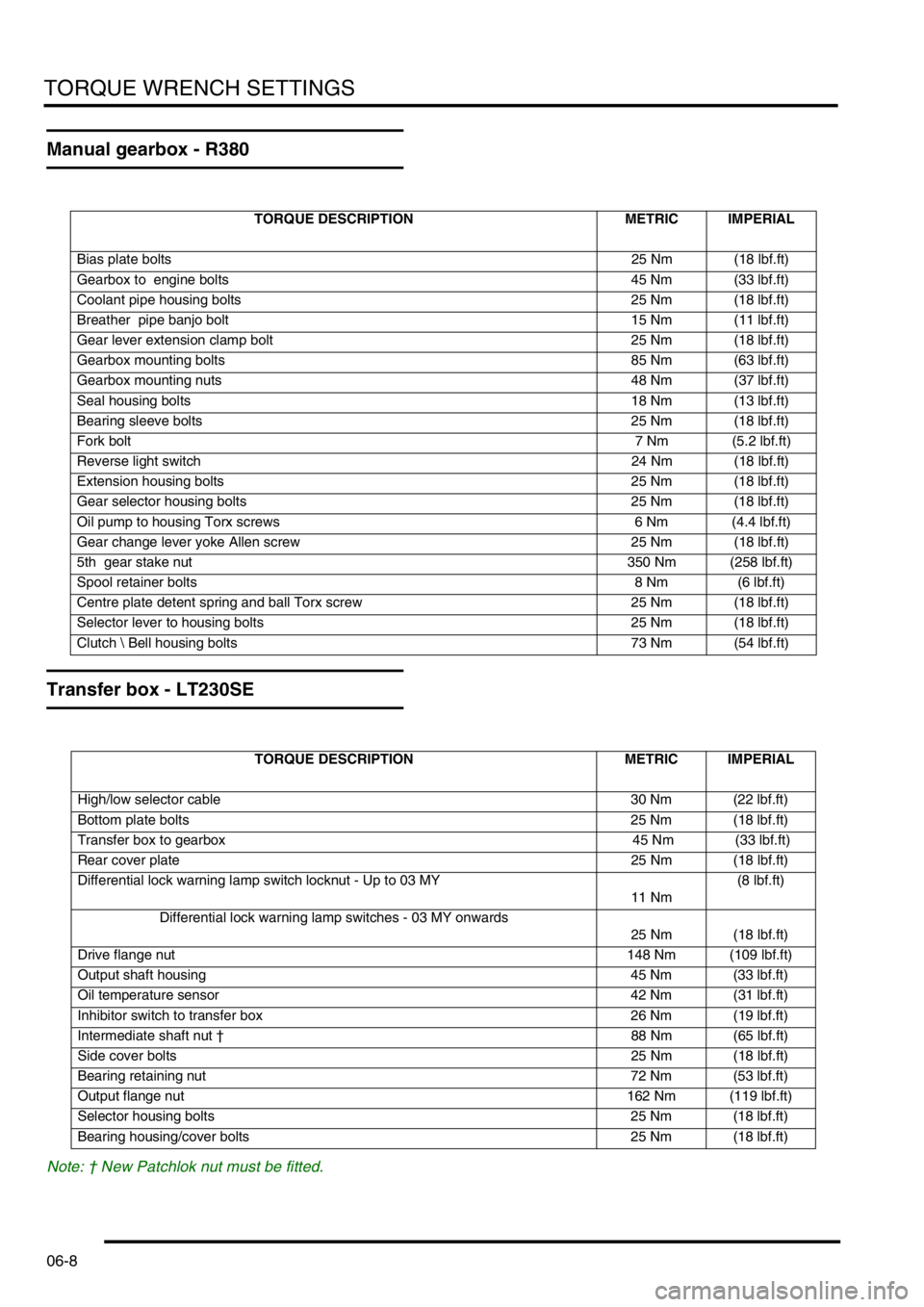
06-8
Manual gearbox - R380
Transfer box - LT230SE
Note: † New Patchlok nut must be fitted.
TORQUE DESCRIPTION METRIC IMPERIAL
Bias plate bolts25 Nm (18 lbf.ft)
Gearbox to engine bolts 45 Nm (33 lbf.ft)
Coolant pipe housing bolts 25 Nm (18 lbf.ft)
Breather pipe banjo bolt 15 Nm (11 lbf.ft)
Gear lever extension clamp bolt 25 Nm (18 lbf.ft)
Gearbox mounting bolts 85 Nm (63 lbf.ft)
Gearbox mounting nuts 48 Nm (37 lbf.ft)
Seal housing bolts 18 Nm (13 lbf.ft)
Bearing sleeve bolts 25 Nm (18 lbf.ft)
Fork bolt7 Nm (5.2 lbf.ft)
Reverse light switch 24 Nm (18 lbf.ft)
Extension housing bolts 25 Nm (18 lbf.ft)
Gear selector housing bolts 25 Nm (18 lbf.ft)
Oil pump to housing Torx screws 6 Nm (4.4 lbf.ft)
Gear change lever yoke Allen screw 25 Nm (18 lbf.ft)
5th gear stake nut 350 Nm (258 lbf.ft)
Spool retainer bolts 8 Nm (6 lbf.ft)
Centre plate detent spring and ball Torx screw 25 Nm (18 lbf.ft)
Selector lever to housing bolts 25 Nm (18 lbf.ft)
Clutch Bell housing bolts 73 Nm (54 lbf.ft)
TORQUE DESCRIPTION METRIC IMPERIAL
High/low selector cable 30 Nm (22 lbf.ft)
Bottom plate bolts 25 Nm (18 lbf.ft)
Transfer box to gearbox 45 Nm (33 lbf.ft)
Rear cover plate25 Nm (18 lbf.ft)
Differential lock warning lamp switch locknut - Up to 03 MY
11 Nm(8 lbf.ft)
Differential lock warning lamp switches - 03 MY onwards
25 Nm (18 lbf.ft)
Drive flange nut148 Nm (109 lbf.ft)
Output shaft housing 45 Nm (33 lbf.ft)
Oil temperature sensor 42 Nm (31 lbf.ft)
Inhibitor switch to transfer box 26 Nm (19 lbf.ft)
Intermediate shaft nut †88 Nm (65 lbf.ft)
Side cover bolts25 Nm (18 lbf.ft)
Bearing retaining nut 72 Nm (53 lbf.ft)
Output flange nut 162 Nm (119 lbf.ft)
Selector housing bolts 25 Nm (18 lbf.ft)
Bearing housing/cover bolts 25 Nm (18 lbf.ft)
Page 99 of 1672
TORQUE WRENCH SETTINGS
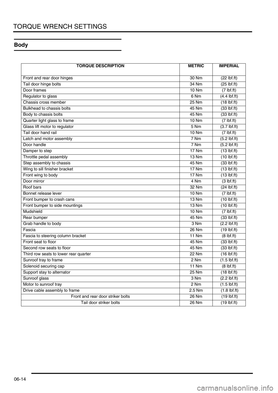
06-14
Body
TORQUE DESCRIPTION METRIC IMPERIAL
Front and rear door hinges 30 Nm (22 lbf.ft)
Tail door hinge bolts 34 Nm (25 lbf.ft)
Door frames10 Nm (7 lbf.ft)
Regulator to glass 6 Nm (4.4 lbf.ft)
Chassis cross member 25 Nm (18 lbf.ft)
Bulkhead to chassis bolts 45 Nm (33 lbf.ft)
Body to chassis bolts 45 Nm (33 lbf.ft)
Quarter light glass to frame 10 Nm (7 lbf.ft)
Glass lift motor to regulator 5 Nm (3.7 lbf.ft)
Tail door hand rail 10 Nm (7 lbf.ft)
Latch and motor assembly 7 Nm (5.2 lbf.ft)
Door handle7 Nm (5.2 lbf.ft)
Damper to step17 Nm (13 lbf.ft)
Throttle pedal assembly 13 Nm (10 lbf.ft)
Step assembly to chassis 45 Nm (33 lbf.ft)
Wing to sill finisher bracket 17 Nm (13 lbf.ft)
Front wing to body 17 Nm (13 lbf.ft)
Door mirror4 Nm (3 lbf.ft)
Roof bars32 Nm (24 lbf.ft)
Bonnet release lever 10 Nm (7 lbf.ft)
Front bumper to crash cans 13 Nm (10 lbf.ft)
Front bumper to side mountings 13 Nm (10 lbf.ft)
Mudshield10 Nm (7 lbf.ft)
Rear bumper45 Nm (33 lbf.ft)
Grab handle to body 3 Nm (2.2 lbf.ft)
Fascia26 Nm (19 lbf.ft)
Fascia to steering column bracket 11 Nm (8 lbf.ft)
Front seat to floor 45 Nm (33 lbf.ft)
Second row seats to floor 45 Nm (33 lbf.ft)
Third row seats to lower rear quarter 22 Nm (16 lbf.ft)
Sunroof tray to frame 2 Nm (1.5 lbf.ft)
Solenoid securing cap 11 Nm (8 lbf.ft)
Support stay to alternator 25 Nm (18 lbf.ft)
Sunroof glass3 Nm (2.2 lbf.ft)
Motor to sunroof tray 2 Nm (1.5 lbf.ft)
Drive cable assembly to frame 2.5 Nm (1.8 lbf.ft)
Front and rear door striker bolts 26 Nm (19 lbf.ft)
Tail door striker bolts 26 Nm (19 lbf.ft)
Page 104 of 1672
LIFTING AND TOWING
08-3
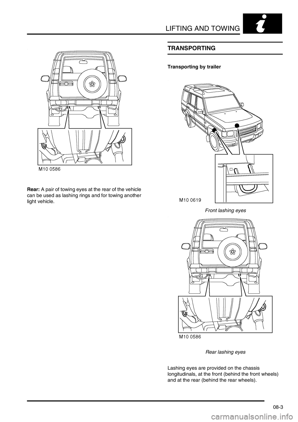
Rear: A pair of towing eyes at the rear of the vehicle
can be used as lashing rings and for towing another
light vehicle.
TRANSPORTING
Transporting by trailer
Front lashing eyes
Rear lashing eyes
Lashing eyes are provided on the chassis
longitudinals, at the front (behind the front wheels)
and at the rear (behind the rear wheels).
Page 114 of 1672
MAINTENANCE
PROCEDURES 10-5
Lamps, horns and warning indicators
Check
1.Switch on side, head and tail lamps and check
operation.
2.Check headlamp levelling operation.
3.Check turn signals and hazard warning lamps
for correct operation.
4.Press brake pedal and check operation of
brake lamps.
5.Check all exterior lamp lenses for clarity and
condition. Pay particular attention to headlamp
lenses for signs of stone chips or damage.
6.Check horn for loud, clear sound.
7.Switch on headlamps (with ignition switch at 'O'
position) and check light reminder warning
operates when door is opened.
8.Check operation of interior courtesy lights.
9.Check operation of all instrument pack warning
and indicator lights.
Wipers and washers
Check
1. Operate screen washer and switch on wipers.
Ensure washer jets are correctly aimed and
check for smooth, smear free operation of
wiper blades across screen at all speeds
including intermittent.
2.Repeat operation for rear screen washers/
wipers.
Page 152 of 1672
ENGINE - TD5
DESCRIPTION AND OPERATION 12-1-13
Two plastic dowels are used to locate the cylinder head to the cylinder block and must be replaced every time the
cylinder head is removed from the cylinder block.
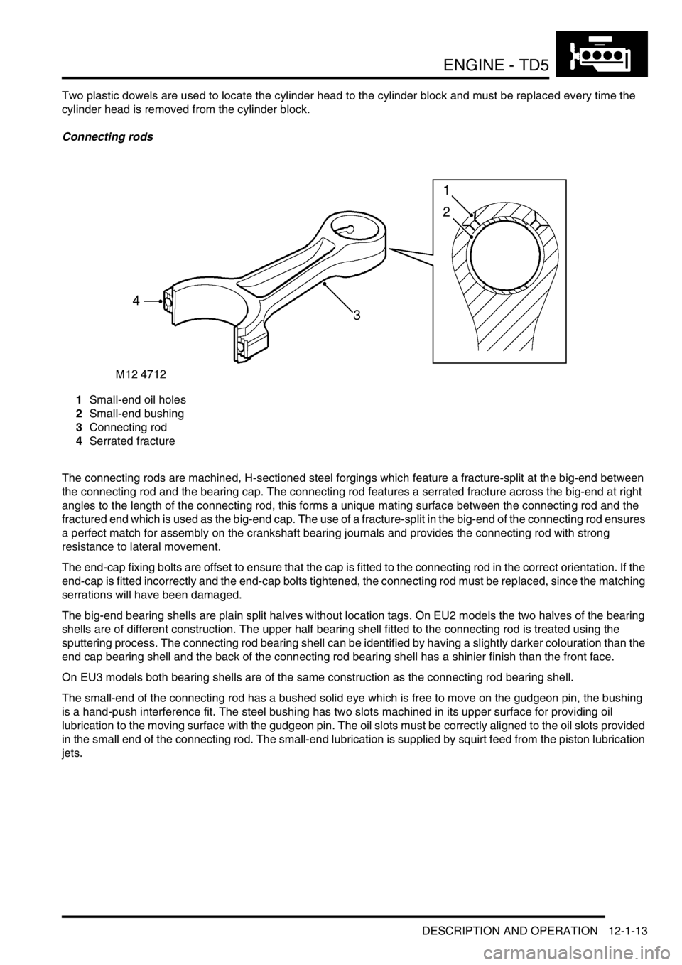
Connecting rods
1Small-end oil holes
2Small-end bushing
3Connecting rod
4Serrated fracture
The connecting rods are machined, H-sectioned steel forgings which feature a fracture-split at the big-end between
the connecting rod and the bearing cap. The connecting rod features a serrated fracture across the big-end at right
angles to the length of the connecting rod, this forms a unique mating surface between the connecting rod and the
fractured end which is used as the big-end cap. The use of a fracture-split in the big-end of the connecting rod ensures
a perfect match for assembly on the crankshaft bearing journals and provides the connecting rod with strong
resistance to lateral movement.
The end-cap fixing bolts are offset to ensure that the cap is fitted to the connecting rod in the correct orientation. If the
end-cap is fitted incorrectly and the end-cap bolts tightened, the connecting rod must be replaced, since the matching
serrations will have been damaged.
The big-end bearing shells are plain split halves without location tags. On EU2 models the two halves of the bearing
shells are of different construction. The upper half bearing shell fitted to the connecting rod is treated using the
sputtering process. The connecting rod bearing shell can be identified by having a slightly darker colouration than the
end cap bearing shell and the back of the connecting rod bearing shell has a shinier finish than the front face.
On EU3 models both bearing shells are of the same construction as the connecting rod bearing shell.
The small-end of the connecting rod has a bushed solid eye which is free to move on the gudgeon pin, the bushing
is a hand-push interference fit. The steel bushing has two slots machined in its upper surface for providing oil
lubrication to the moving surface with the gudgeon pin. The oil slots must be correctly aligned to the oil slots provided
in the small end of the connecting rod. The small-end lubrication is supplied by squirt feed from the piston lubrication
jets.
Page 158 of 1672
ENGINE - TD5
DESCRIPTION AND OPERATION 12-1-19
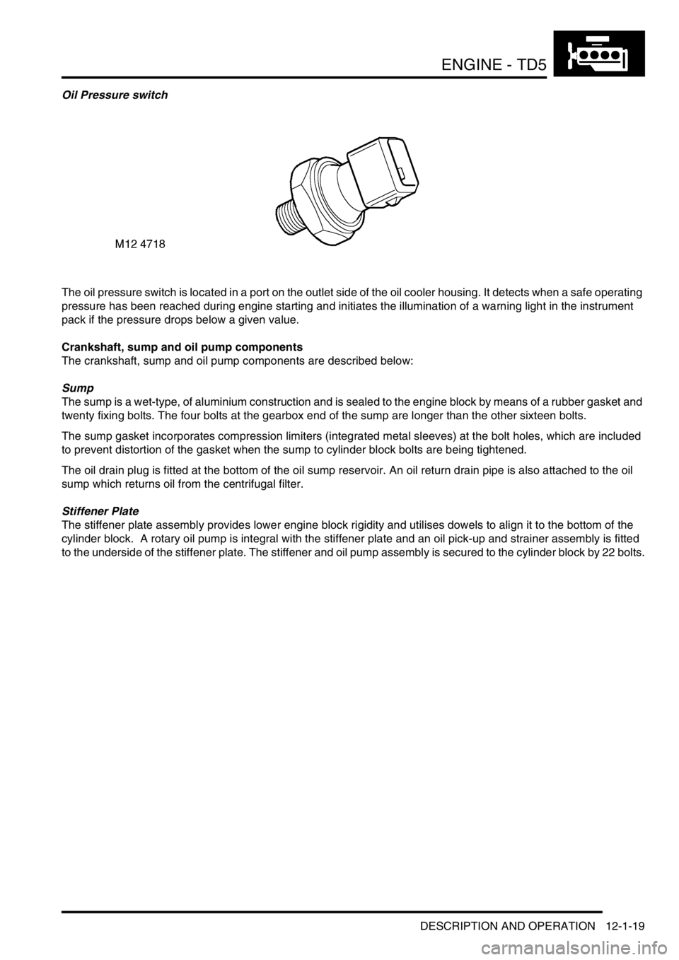
Oil Pressure switch
The oil pressure switch is located in a port on the outlet side of the oil cooler housing. It detects when a safe operating
pressure has been reached during engine starting and initiates the illumination of a warning light in the instrument
pack if the pressure drops below a given value.
Crankshaft, sump and oil pump components
The crankshaft, sump and oil pump components are described below:
Sump
The sump is a wet-type, of aluminium construction and is sealed to the engine block by means of a rubber gasket and
twenty fixing bolts. The four bolts at the gearbox end of the sump are longer than the other sixteen bolts.
The sump gasket incorporates compression limiters (integrated metal sleeves) at the bolt holes, which are included
to prevent distortion of the gasket when the sump to cylinder block bolts are being tightened.
The oil drain plug is fitted at the bottom of the oil sump reservoir. An oil return drain pipe is also attached to the oil
sump which returns oil from the centrifugal filter.
Stiffener Plate
The stiffener plate assembly provides lower engine block rigidity and utilises dowels to align it to the bottom of the
cylinder block. A rotary oil pump is integral with the stiffener plate and an oil pick-up and strainer assembly is fitted
to the underside of the stiffener plate. The stiffener and oil pump assembly is secured to the cylinder block by 22 bolts.