torque LAND ROVER DISCOVERY 2002 Owner's Manual
[x] Cancel search | Manufacturer: LAND ROVER, Model Year: 2002, Model line: DISCOVERY, Model: LAND ROVER DISCOVERY 2002Pages: 1672, PDF Size: 46.1 MB
Page 99 of 1672

TORQUE WRENCH SETTINGS
06-14
Body
TORQUE DESCRIPTION METRIC IMPERIAL
Front and rear door hinges 30 Nm (22 lbf.ft)
Tail door hinge bolts 34 Nm (25 lbf.ft)
Door frames10 Nm (7 lbf.ft)
Regulator to glass 6 Nm (4.4 lbf.ft)
Chassis cross member 25 Nm (18 lbf.ft)
Bulkhead to chassis bolts 45 Nm (33 lbf.ft)
Body to chassis bolts 45 Nm (33 lbf.ft)
Quarter light glass to frame 10 Nm (7 lbf.ft)
Glass lift motor to regulator 5 Nm (3.7 lbf.ft)
Tail door hand rail 10 Nm (7 lbf.ft)
Latch and motor assembly 7 Nm (5.2 lbf.ft)
Door handle7 Nm (5.2 lbf.ft)
Damper to step17 Nm (13 lbf.ft)
Throttle pedal assembly 13 Nm (10 lbf.ft)
Step assembly to chassis 45 Nm (33 lbf.ft)
Wing to sill finisher bracket 17 Nm (13 lbf.ft)
Front wing to body 17 Nm (13 lbf.ft)
Door mirror4 Nm (3 lbf.ft)
Roof bars32 Nm (24 lbf.ft)
Bonnet release lever 10 Nm (7 lbf.ft)
Front bumper to crash cans 13 Nm (10 lbf.ft)
Front bumper to side mountings 13 Nm (10 lbf.ft)
Mudshield10 Nm (7 lbf.ft)
Rear bumper45 Nm (33 lbf.ft)
Grab handle to body 3 Nm (2.2 lbf.ft)
Fascia26 Nm (19 lbf.ft)
Fascia to steering column bracket 11 Nm (8 lbf.ft)
Front seat to floor 45 Nm (33 lbf.ft)
Second row seats to floor 45 Nm (33 lbf.ft)
Third row seats to lower rear quarter 22 Nm (16 lbf.ft)
Sunroof tray to frame 2 Nm (1.5 lbf.ft)
Solenoid securing cap 11 Nm (8 lbf.ft)
Support stay to alternator 25 Nm (18 lbf.ft)
Sunroof glass3 Nm (2.2 lbf.ft)
Motor to sunroof tray 2 Nm (1.5 lbf.ft)
Drive cable assembly to frame 2.5 Nm (1.8 lbf.ft)
Front and rear door striker bolts 26 Nm (19 lbf.ft)
Tail door striker bolts 26 Nm (19 lbf.ft)
Page 100 of 1672
TORQUE WRENCH SETTINGS
06-15
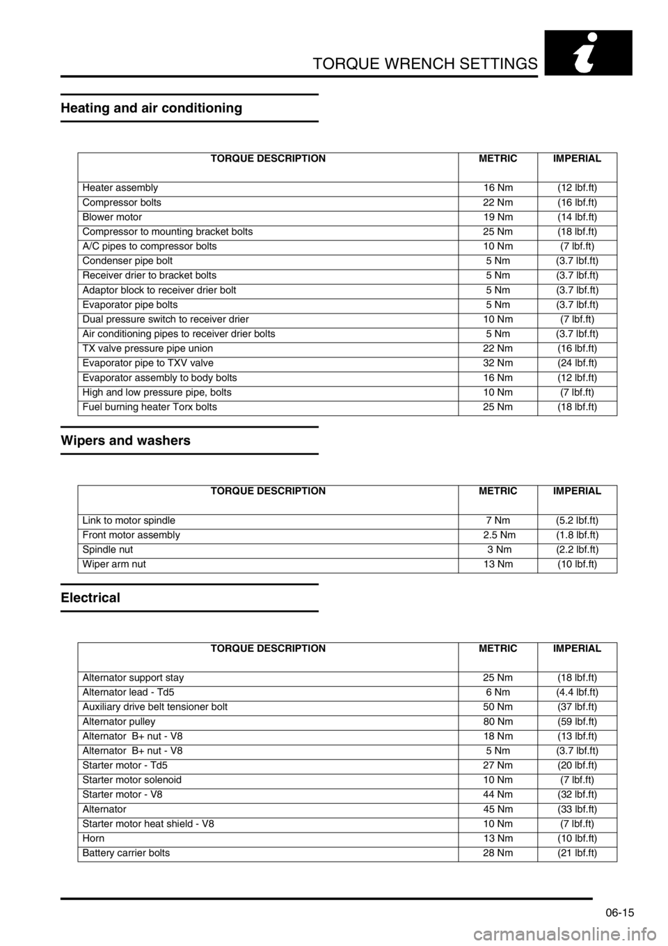
Heating and air conditioning
Wipers and washers
Electrical
TORQUE DESCRIPTION METRIC IMPERIAL
Heater assembly16 Nm (12 lbf.ft)
Compressor bolts 22 Nm (16 lbf.ft)
Blower motor19 Nm (14 lbf.ft)
Compressor to mounting bracket bolts 25 Nm (18 lbf.ft)
A/C pipes to compressor bolts 10 Nm (7 lbf.ft)
Condenser pipe bolt 5 Nm (3.7 lbf.ft)
Receiver drier to bracket bolts 5 Nm (3.7 lbf.ft)
Adaptor block to receiver drier bolt 5 Nm (3.7 lbf.ft)
Evaporator pipe bolts 5 Nm (3.7 lbf.ft)
Dual pressure switch to receiver drier 10 Nm (7 lbf.ft)
Air conditioning pipes to receiver drier bolts 5 Nm (3.7 lbf.ft)
TX valve pressure pipe union 22 Nm (16 lbf.ft)
Evaporator pipe to TXV valve 32 Nm (24 lbf.ft)
Evaporator assembly to body bolts 16 Nm (12 lbf.ft)
High and low pressure pipe, bolts 10 Nm (7 lbf.ft)
Fuel burning heater Torx bolts 25 Nm (18 lbf.ft)
TORQUE DESCRIPTION METRIC IMPERIAL
Link to motor spindle 7 Nm (5.2 lbf.ft)
Front motor assembly 2.5 Nm (1.8 lbf.ft)
Spindle nut 3 Nm (2.2 lbf.ft)
Wiper arm nut13 Nm (10 lbf.ft)
TORQUE DESCRIPTION METRIC IMPERIAL
Alternator support stay 25 Nm (18 lbf.ft)
Alternator lead - Td5 6 Nm (4.4 lbf.ft)
Auxiliary drive belt tensioner bolt 50 Nm (37 lbf.ft)
Alternator pulley80 Nm (59 lbf.ft)
Alternator B+ nut - V8 18 Nm (13 lbf.ft)
Alternator B+ nut - V8 5 Nm (3.7 lbf.ft)
Starter motor - Td5 27 Nm (20 lbf.ft)
Starter motor solenoid 10 Nm (7 lbf.ft)
Starter motor - V8 44 Nm (32 lbf.ft)
Alternator45 Nm (33 lbf.ft)
Starter motor heat shield - V8 10 Nm (7 lbf.ft)
Horn13 Nm (10 lbf.ft)
Battery carrier bolts 28 Nm (21 lbf.ft)
Page 101 of 1672

TORQUE WRENCH SETTINGS
06-16
Page 129 of 1672
MAINTENANCE
10-20 PROCEDURES
5.Apply recommended grease to the grease
nipple.
+ CAPACITIES, FLUIDS AND
LUBRICANTS, Lubrication.
6.Remove grease nipple.
7.Fit blanking plug.
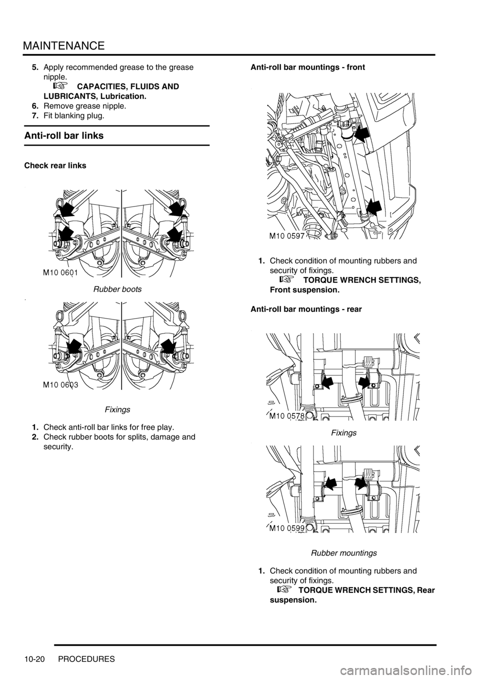
Anti-roll bar links
Check rear links
Rubber boots
Fixings
1.Check anti-roll bar links for free play.
2.Check rubber boots for splits, damage and
security.Anti-roll bar mountings - front
1.Check condition of mounting rubbers and
security of fixings.
+ TORQUE WRENCH SETTINGS,
Front suspension.
Anti-roll bar mountings - rear
Fixings
Rubber mountings
1.Check condition of mounting rubbers and
security of fixings.
+ TORQUE WRENCH SETTINGS, Rear
suspension.
Page 133 of 1672

MAINTENANCE
10-24 PROCEDURES
1.Check/tighten front suspension LH radius arm
fixings.
+ TORQUE WRENCH SETTINGS,
Front suspension.
2.Check/tighten front suspension RH radius arm
fixings.3.Check/tighten front suspension Panhard rod
fixings
Check rear axle suspension fixings
Page 134 of 1672
MAINTENANCE
PROCEDURES 10-25
1.Check and tighten if necessary all rear axle
suspension fixings.
+ TORQUE WRENCH SETTINGS, Rear
suspension.
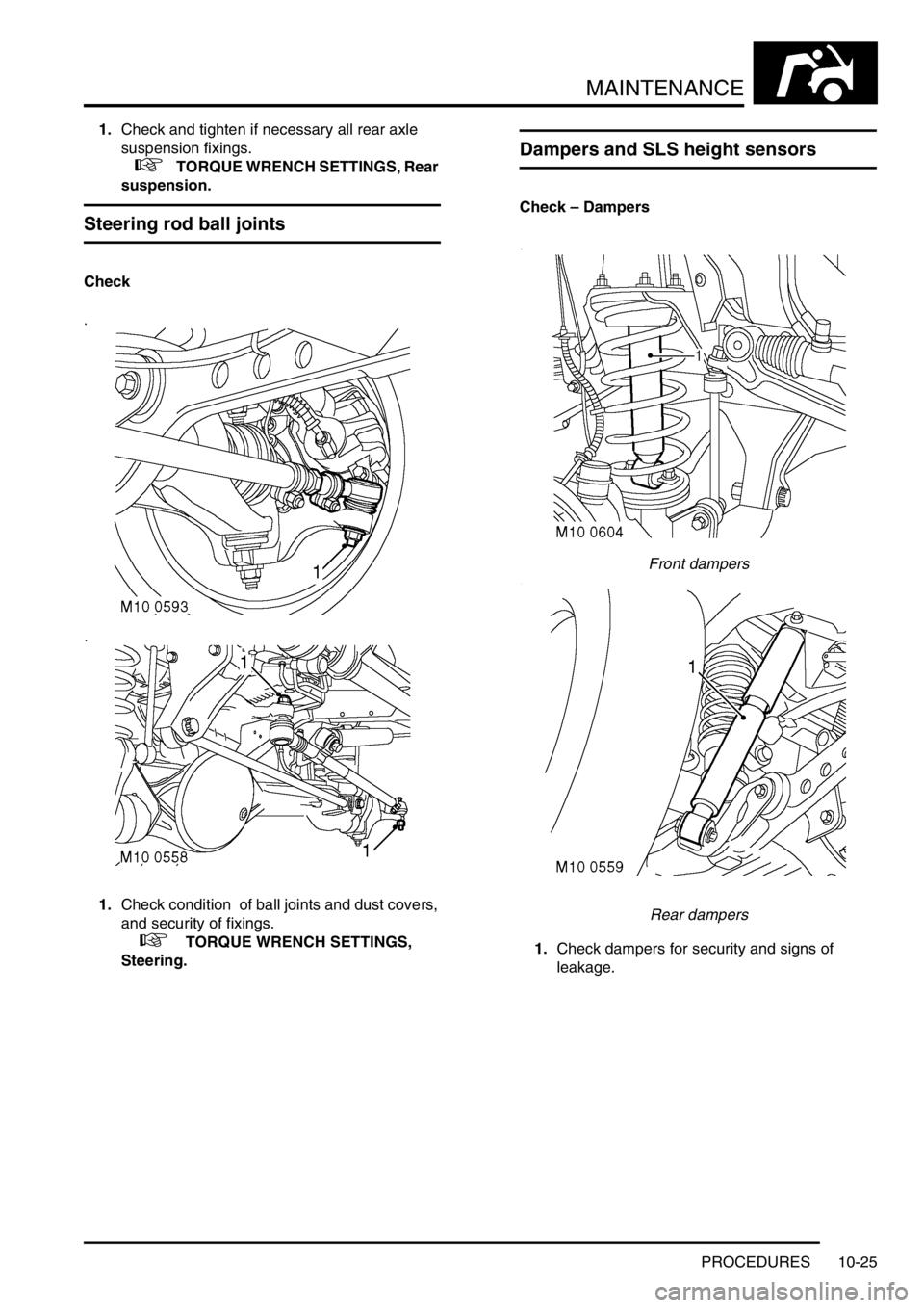
Steering rod ball joints
Check
1.Check condition of ball joints and dust covers,
and security of fixings.
+ TORQUE WRENCH SETTINGS,
Steering.
Dampers and SLS height sensors
Check – Dampers
Front dampers
Rear dampers
1.Check dampers for security and signs of
leakage.
Page 136 of 1672
MAINTENANCE
PROCEDURES 10-27
2.Check security of fixings.
+ TORQUE WRENCH SETTINGS,
Front suspension.
+ TORQUE WRENCH SETTINGS, Rear
suspension.
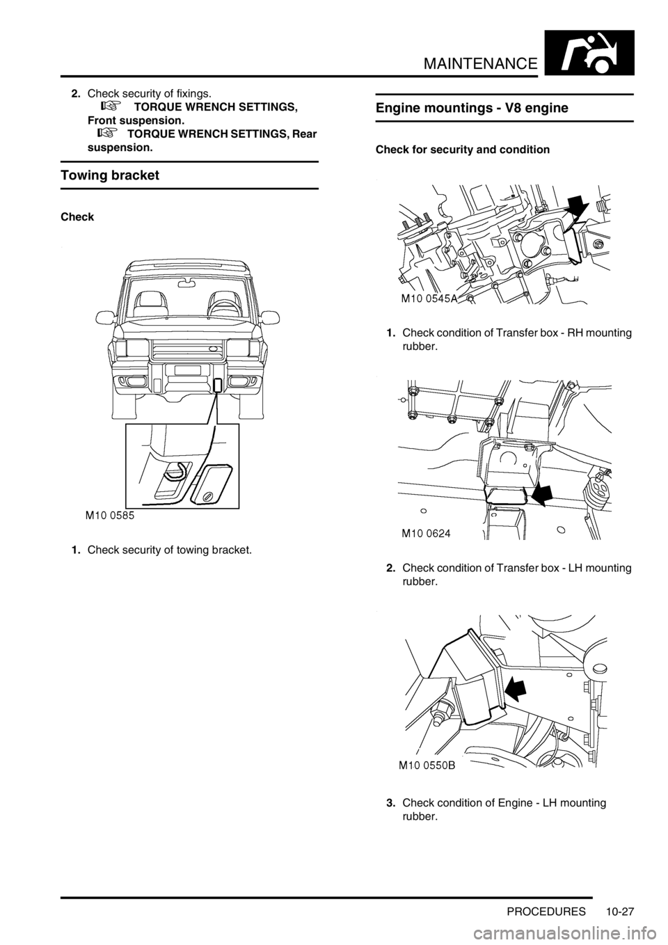
Towing bracket
Check
1.Check security of towing bracket.
Engine mountings - V8 engine
Check for security and condition
1.Check condition of Transfer box - RH mounting
rubber.
2.Check condition of Transfer box - LH mounting
rubber.
3.Check condition of Engine - LH mounting
rubber.
Page 137 of 1672
MAINTENANCE
10-28 PROCEDURES
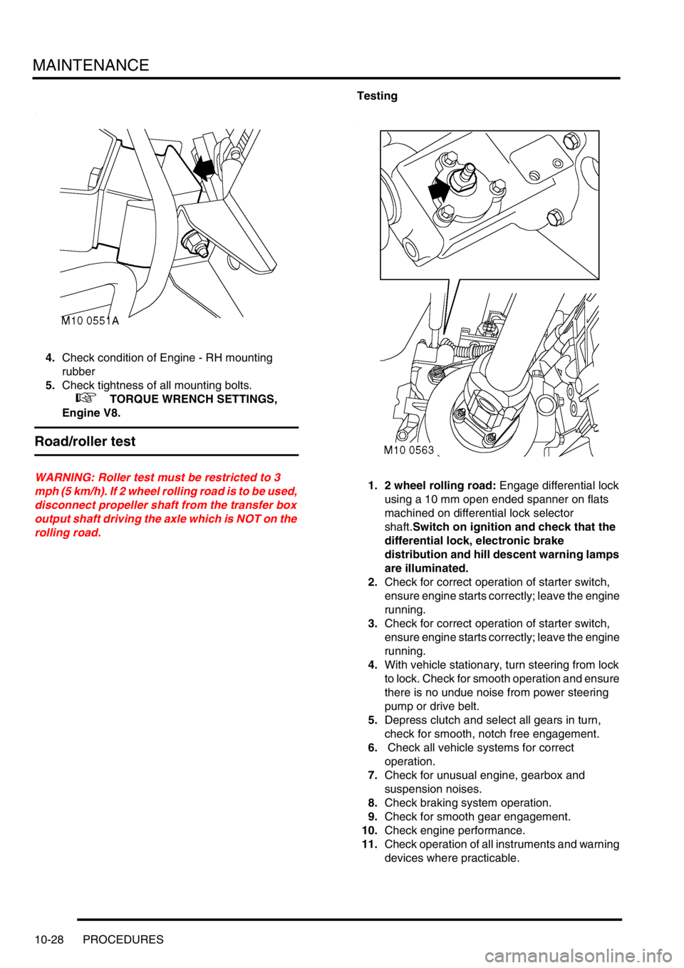
4.Check condition of Engine - RH mounting
rubber
5.Check tightness of all mounting bolts.
+ TORQUE WRENCH SETTINGS,
Engine V8.
Road/roller test
WARNING: Roller test must be restricted to 3
mph (5 km/h). If 2 wheel rolling road is to be used,
disconnect propeller shaft from the transfer box
output shaft driving the axle which is NOT on the
rolling road.Testing
1. 2 wheel rolling road: Engage differential lock
using a 10 mm open ended spanner on flats
machined on differential lock selector
shaft.Switch on ignition and check that the
differential lock, electronic brake
distribution and hill descent warning lamps
are illuminated.
2.Check for correct operation of starter switch,
ensure engine starts correctly; leave the engine
running.
3.Check for correct operation of starter switch,
ensure engine starts correctly; leave the engine
running.
4.With vehicle stationary, turn steering from lock
to lock. Check for smooth operation and ensure
there is no undue noise from power steering
pump or drive belt.
5.Depress clutch and select all gears in turn,
check for smooth, notch free engagement.
6. Check all vehicle systems for correct
operation.
7.Check for unusual engine, gearbox and
suspension noises.
8.Check braking system operation.
9.Check for smooth gear engagement.
10.Check engine performance.
11.Check operation of all instruments and warning
devices where practicable.
Page 176 of 1672

ENGINE - TD5
REPAIRS 12-1-37
REPAIRS
Pulley - crankshaft
$% 12.21.01
Remove
1.Remove fixings and underbelly panel.
2.Remove radiator.
+ COOLING SYSTEM - Td5, REPAIRS,
Radiator.
3.Using a 15 mm ring spanner, release the
auxiliary drive belt tensioner.
4.Remove auxiliary drive belt.
5.Remove 3 bolts and remove crankshaft TV
damper.
6.Position tool LRT-51-003 to crankshaft pulley
and secure with 2 bolts.
7.Remove and discard crankshaft pulley bolt.
Remove crankshaft pulley.
8.Remove 2 bolts and remove tool LRT-51-003
Refit
1.Position new crankshaft pulley to vice.
2.Remove 3 bolts and remove TV damper from
new crankshaft pulley.
3.Using a lint free cloth, thoroughly clean oil seal
recess and the running surface on crankshaft
pulley.
4.Fit crankshaft pulley. 5.Fit tool LRT-51-003 to crankshaft pulley and
secure with 2 bolts.
6.Fit new crankshaft pulley bolt and tighten to
460 Nm (340 lbf.ft), using a torque multiplier.
7.Remove 2 bolts and remove tool LRT-51-003
from crankshaft pulley.
8.Fit TV damper to crankshaft pulley and tighten
– TV damper bolts to 80 Nm (59 lbf.ft) .
9.Fit auxiliary drive belt to pulleys.
10.Fit radiator.
+ COOLING SYSTEM - Td5, REPAIRS,
Radiator.
11.Fit underbelly panel and secure with fixings.
Page 189 of 1672
ENGINE - TD5
12-1-50 REPAIRS
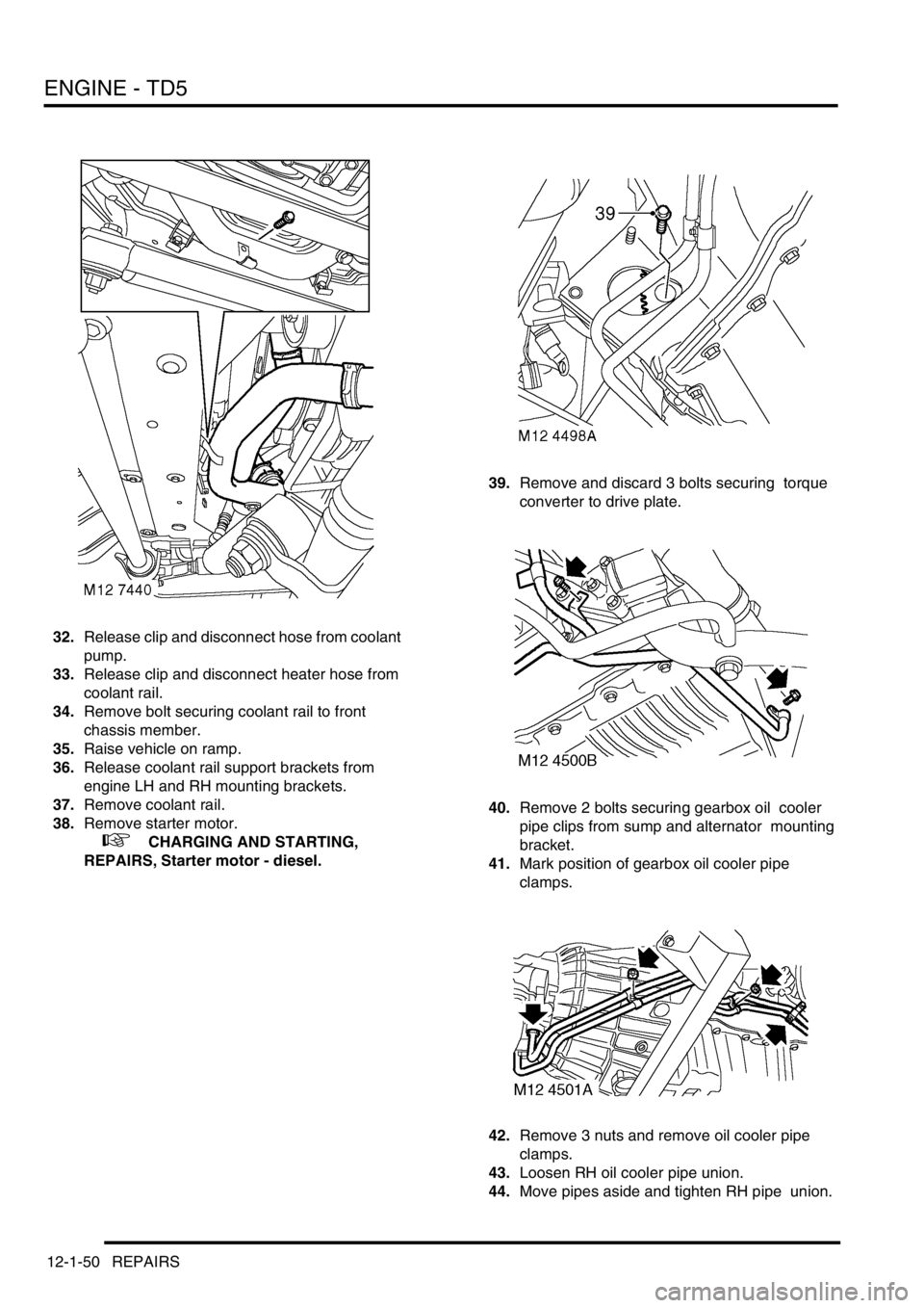
32.Release clip and disconnect hose from coolant
pump.
33.Release clip and disconnect heater hose from
coolant rail.
34.Remove bolt securing coolant rail to front
chassis member.
35.Raise vehicle on ramp.
36.Release coolant rail support brackets from
engine LH and RH mounting brackets.
37.Remove coolant rail.
38.Remove starter motor.
+ CHARGING AND STARTING,
REPAIRS, Starter motor - diesel.39.Remove and discard 3 bolts securing torque
converter to drive plate.
40.Remove 2 bolts securing gearbox oil cooler
pipe clips from sump and alternator mounting
bracket.
41.Mark position of gearbox oil cooler pipe
clamps.
42.Remove 3 nuts and remove oil cooler pipe
clamps.
43.Loosen RH oil cooler pipe union.
44.Move pipes aside and tighten RH pipe union.