torque LAND ROVER DISCOVERY 2002 Repair Manual
[x] Cancel search | Manufacturer: LAND ROVER, Model Year: 2002, Model line: DISCOVERY, Model: LAND ROVER DISCOVERY 2002Pages: 1672, PDF Size: 46.1 MB
Page 746 of 1672

TRANSFER BOX - LT230SE
DESCRIPTION AND OPERATION 41-13
Description
General
The LT 230SE transfer box is mounted at the rear of the gearbox and transmits drive via high or low reduction ratios
to the front and rear axles via the propeller shafts. The high/low ratios are 1.211:1 and 3.32:1 respectively.
Transfer boxes fitted to this model have the prefixes 41D and 42D to the unit serial number. Prefix 41D denotes that
the unit is not fitted with interlock whilst 42D denotes that interlock is fitted.
Vehicles up to 03 model year – Whilst similar to LT230Q transfer boxes fitted to other models, the LT230SE transfer
box has certain engineering modifications incorporated which are as follows:
lUprated torque capacity
lModified front and rear output and cross shaft housings
lIntermediate gear bearing pre-load now controlled by a selective, non-collapsible spacer
lSpeedometer drive and driven gears not fitted for this application
lModified high/low sleeve
lModified front output flange and mud shield
lDifferential lock fitted to certain vehicles, but no longer driver operated
lFixed setting of differential lock warning lamp switch on vehicles fitted with differential lock
Vehicles from 03 model year – The LT230SE transfer box is as described above for vehicles up to 03 model year
with the following modifications:
The following items are introduced on vehicles from 03 model year
lRibs added to main casing to reduce operating noise
lBearing retaining nut on the differential carrier has patchlock added to the threads
lInterlock solenoid moved from main casing to selector lever assembly
lIntermediate gears modified with machined internal shoulder and bearing circlips deleted
The following items are introduced later in the 03 model year build programme and therefore may not appear on all
03 model year vehicles
lDriver operated differential lock (if fitted)
lHigh/Low selector shaft fitted with spring assist
lExisting differential lock switch replaced by new design switch.
lNew secondary differential lock switch installed in the front output housing
Construction
The transfer box comprises three main assemblies; the main casing, the front output housing and the rear output
housing. Both output housings and all cover plates are sealed to the main casing by sealant; mud and water ingress
being prevented by mud shields located on the output flanges.
Main casing
The main casing carries the mainshaft input gear, the intermediate gears and the differential, together with the high/
low range gears, selector shaft and fork. The front and rear output housings are bolted to either side of the main
casing.
Transmission neutral sensor
A transmission neutral sensor is fitted on automatic gearbox vehicles for North America and Japan. The sensor is
connected to the BCU and is normally in the open position. The sensor provides an earth path for the BCU which then
interprets the signal and activates an audible warning generated by the IDM if neutral is selected on the transfer box
when the ignition is on.
Page 747 of 1672

TRANSFER BOX - LT230SE
41-14 DESCRIPTION AND OPERATION
Transfer box interlock solenoid - Automatic gearbox vehicles
An interlock solenoid is fitted for North America and Japan. The solenoid is located on the top of the transfer box main
casing on vehicles up to 03 model year or on the selector lever assembly on vehicles from 03 model year. The
solenoid is connected to the transfer box relay which, in turn, is controlled by the IDM. The purpose of the solenoid is
to prevent neutral being selected on the transfer box when the ignition key is removed, thereby locking the box in
either high or low ratio.
Mainshaft input gear
The gearbox output shaft is splined into the mainshaft input gear which is supported by taper roller bearings.
Input gear bearing pre-load is achieved by the use of a selective shim located in the bearing housing.
Intermediate gears
The intermediate gear cluster is supported by the taper roller bearings located at each end of the cluster and runs on
the intermediate shaft which, in turn, is supported at the front and rear by the main casing.
A selective spacer, positioned between the gears, pre-loads the intermediate gear bearings when the intermediate
shaft nut is tightened sufficiently to achieve the correct 'torque to turn' of the intermediate gears.
On vehicles from 03 model year, the circlips used to retain the bearings in the intermediate gear are deleted. The bore
of the intermediate gear is machined with a shoulder at each end to locate the bearings.
Differential assembly
The differential assembly is supported at the front and rear by taper roller bearings, the front bearing outer track is
located in the front output housing and the rear bearing outer track is located in the main casing by the rear output
housing. Bearing pre-load is achieved by means of a selective shim located in the front output housing.
The differential rear shaft carries the low range gear, high/low selector sleeve and hub, high range gear and bush and
the differential rear bearing; these components being secured to the shaft by a special staked nut.
The differential assembly comprises front and rear half carriers with integral shafts and with sun and planet gears
mounted on cross shafts within the half carriers. Dished, non-selective thrust washers control the engagement of the
planet gears with the sun gears, whilst selective thrust washers are used to control engagement of the sun gears and
'torque to turn' of the differential. The differential carrier halves are bolted together, a retaining ring providing positive
location of the cross shafts.
The high/low selector shaft and fork are located at the side of the differential, movement of the shaft, fork and selector
sleeve being controlled by the high/low selector finger. A spring loaded detent ball fitted in the main casing, locates
in grooves in the shaft.
On vehicles from 03 model year, the selector fork is modified and fitted with a spring assistor and clips to reduce the
effort required to move the selector lever.
Front output housing
The front output housing carries the front output shaft and flange, high/low cross shaft, housing and selector and on
certain vehicles, the differential lock selector shaft and fork.
The front output shaft is supported in the housing by a single bearing and is splined into the differential front sun gear.
High/low selector
The high/low cross shaft is located in a housing bolted to the top of the output housing and is connected to the high/
low selector finger which locates in a slot in the selector shaft.
Page 775 of 1672

TRANSFER BOX - LT230SE
41-42 OVERHAUL
18.Select neutral.
19.Screw a suitable bolt into tapped hole of tool
LRT-41-005.
20.Insert tool LRT-41-005 in end of mainshaft.
21.Using a suitable torque meter on tool LRT-41-
005, check torque to turn of gear train. Torque
to turn = 2.2 Nm (19 lbf.ft). If torque to turn
figure is incorrect, repeat intermediate gear
bearing pre-load setting and re-check.
22.On completion, remove tool LRT-41-005 and
stake flange of nut into recess on intermediate
shaft.
23.Clean transfer box bottom and side covers.
24.Apply sealant, Part No. STC 3254 to both
covers.
25.Clean bottom and side cover bolt threads.
26.Apply Loctite 290 to bolt threads.
27.Position side cover and tighten bolts to 25 Nm
(18 lbf.ft).
28.Position bottom cover and tighten bolts to 25
Nm (18 lbf.ft).
Differential assembly
$% 41.20.13
Remove
1.Remove intermediate gear cluster.
+ TRANSFER BOX - LT230SE,
OVERHAUL, Intermediate gear assembly.
2.Remove 6 bolts securing high/low cross shaft
housing to front output shaft housing and
remove housing.
3.Note position of longest bolt and remove 8 bolts
securing front output shaft housing to main
casing and remove housing.
Note: Carry out the following operations if
differential lock is fitted.
Page 801 of 1672

AUTOMATIC GEARBOX - ZF4HP22 - 24
44-4 DESCRIPTION AND OPERATION
Description
General
The automatic gearbox is a four speed unit with electronic control of gear selection, shift quality and torque converter
lock-up. Selections on the selector lever assembly are transmitted to the gearbox by a selector cable. A gear position
switch on the gearbox transmits the gear selection to an Electronic Automatic Transmission (EAT) ECU, which
outputs the appropriate control signals to an electro-hydraulic valve block in the gearbox. A mode switch enables the
driver to change the control mode of the EAT ECU. The EAT ECU operates warning lamps in the instrument pack to
indicate the control mode and system status.
The gearbox features a pressure lubrication system and is cooled by pumping the lubricant through an oil cooler.
On NAS market vehicles from 03 model year, the ZF 4HP24 transmission unit is introduced for use with the 4.6 litre
V8 engine. This transmission is required to accomodate the increased power output of the larger engine. The ZF
4HP22 transmission remains in use on vehicles with Td5 and 4.0 litre V8 engines.
Both transmission units are of similar construction, with the ZF 4HP24 unit being 15 mm longer than the 4HP22 unit
to accomodate a larger fluid pump. The operation of both transmission units is the same.
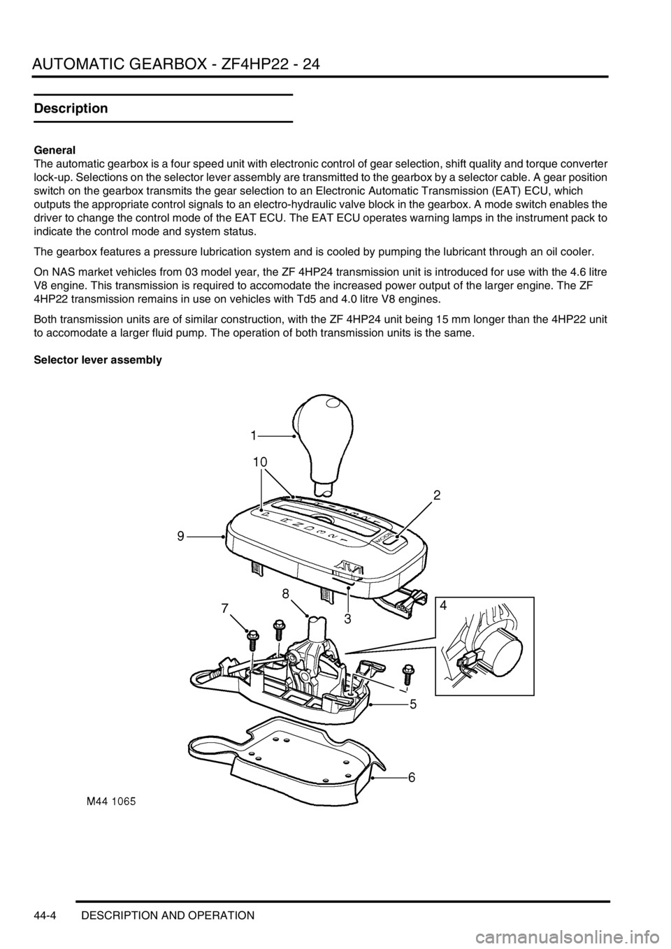
Selector lever assembly
Page 803 of 1672

AUTOMATIC GEARBOX - ZF4HP22 - 24
44-6 DESCRIPTION AND OPERATION
Gearbox
Diesel gearbox shown, V8 gearbox similar
1Torque converter
2Torque converter housing
3Fluid pump
4Breather tube
5Intermediate plate
6Gearbox housing
7Rear extension housing
8Electrical connector
9Gear position switch
10Selector lever
11Mounting bracket12Heat shield
13Rubber mounting
14Gasket
15Sump
16'O' ring seal
17Drain plug
18'O' ring seal
19Filler/level plug
20Bolt
21Clamp
Page 804 of 1672

AUTOMATIC GEARBOX - ZF4HP22 - 24
DESCRIPTION AND OPERATION 44-7
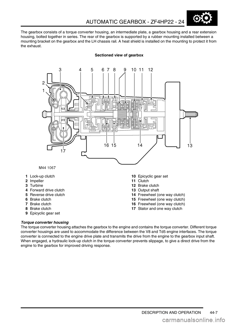
The gearbox consists of a torque converter housing, an intermediate plate, a gearbox housing and a rear extension
housing, bolted together in series. The rear of the gearbox is supported by a rubber mounting installed between a
mounting bracket on the gearbox and the LH chassis rail. A heat shield is installed on the mounting to protect it from
the exhaust.
Sectioned view of gearbox
1Lock-up clutch
2Impeller
3Turbine
4Forward drive clutch
5Reverse drive clutch
6Brake clutch
7Brake clutch
8Brake clutch
9Epicyclic gear set10Epicyclic gear set
11Clutch
12Brake clutch
13Output shaft
14Freewheel (one way clutch)
15Freewheel (one way clutch)
16Freewheel (one way clutch)
17Stator and one way clutch
Torque converter housing
The torque converter housing attaches the gearbox to the engine and contains the torque converter. Different torque
converter housings are used to accommodate the difference between the V8 and Td5 engine interfaces. The torque
converter is connected to the engine drive plate and transmits the drive from the engine to the gearbox input shaft.
When engaged, a hydraulic lock-up clutch in the torque converter prevents slippage, to give a direct drive from the
engine to the gearbox for improved driving response.
Page 805 of 1672

AUTOMATIC GEARBOX - ZF4HP22 - 24
44-8 DESCRIPTION AND OPERATION
Intermediate plate
The intermediate plate supports the gearbox input shaft and provides the interface between the transmission fluid
pump and the lubrication circuit. The pump attaches to the front of the intermediate plate and is driven by the impeller
in the torque converter. The pump pressurises transmission fluid drawn from the sump on the gearbox housing. The
pressurised fluid then circulates through the torque converter and gearbox housing components for cooling,
lubrication and gear shift purposes. Ports around the outer periphery of the intermediate plate provide the inlet and
outlet connections to the fluid cooler and a pressure take-off point for servicing.
Gearbox housing
The gearbox housing contains two epicyclic gear sets on input and output shafts. Hydraulic brake clutches on the
shafts, control which elements of the gear sets are engaged, and their direction of rotation, to produce the P and N
selections, four forward gear ratios and one reverse gear ratio.
Gear ratios
Gear Ratio
1st 2.480 : 1
2nd 1.480 : 1
3rd 1.000 : 1
4th 0.728 : 1
Reverse 2.086 : 1
Page 810 of 1672

AUTOMATIC GEARBOX - ZF4HP22 - 24
DESCRIPTION AND OPERATION 44-13
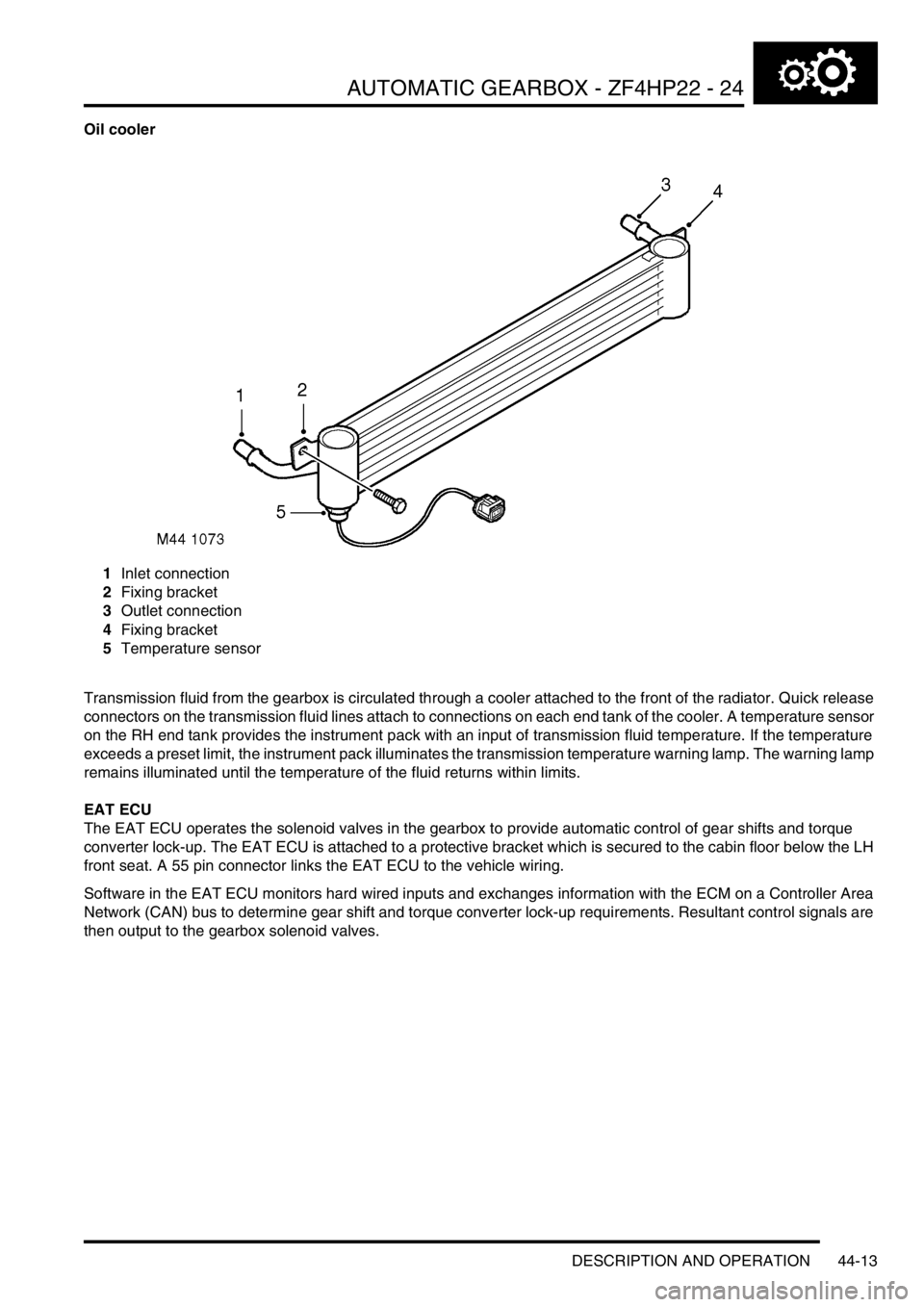
Oil cooler
1Inlet connection
2Fixing bracket
3Outlet connection
4Fixing bracket
5Temperature sensor
Transmission fluid from the gearbox is circulated through a cooler attached to the front of the radiator. Quick release
connectors on the transmission fluid lines attach to connections on each end tank of the cooler. A temperature sensor
on the RH end tank provides the instrument pack with an input of transmission fluid temperature. If the temperature
exceeds a preset limit, the instrument pack illuminates the transmission temperature warning lamp. The warning lamp
remains illuminated until the temperature of the fluid returns within limits.
EAT ECU
The EAT ECU operates the solenoid valves in the gearbox to provide automatic control of gear shifts and torque
converter lock-up. The EAT ECU is attached to a protective bracket which is secured to the cabin floor below the LH
front seat. A 55 pin connector links the EAT ECU to the vehicle wiring.
Software in the EAT ECU monitors hard wired inputs and exchanges information with the ECM on a Controller Area
Network (CAN) bus to determine gear shift and torque converter lock-up requirements. Resultant control signals are
then output to the gearbox solenoid valves.
Page 812 of 1672

AUTOMATIC GEARBOX - ZF4HP22 - 24
DESCRIPTION AND OPERATION 44-15
CAN communications between EAT ECU and ECM
Inputs from ECM Outputs to ECM
CAN version identifier Calculated gear
Emissions (OBD II) control Diagnostic information
Engine air intake temperature Emission (OBD II) fault status
Engine speed Engine torque reduction request
Engine speed fault flag Gear position switch information
Engine temperature Output shaft speed
Engine torque Mode information
Engine torque fault flag Shift information
Friction torque Torque converter lock-up status
Maximum engine torque
Reduced engine torque
Road speed
Status of engine torque reduction
Throttle position
Page 814 of 1672

AUTOMATIC GEARBOX - ZF4HP22 - 24
DESCRIPTION AND OPERATION 44-17
Operation
Refer to illustration.
+ AUTOMATIC GEARBOX - ZF4HP22 - 24, DESCRIPTION AND OPERATION, Control schematic.
When the ignition is switched on, a bulb check is performed on the transmission temperature warning lamp and the
mode warning lamps by the instrument pack and the EAT ECU respectively. The warning lamps are illuminated for
approximately 3 seconds and then extinguished.
The gear position switch outputs are monitored by the BCU and the EAT ECU. The BCU outputs gear position signals
to illuminate the position indicators each side of the gear selector lever and on the odometer LCD in the instrument
pack.
In D, 3, 2, and 1, the EAT ECU outputs control signals to the gearbox to select the required gear.
In D, all forward gears are available for selection by the EAT ECU. In 3, 2 and 1, a corresponding limit is imposed on
the highest gear available for selection. When R is selected, reverse gear only engages if the vehicle is stationary or
moving at 5 mph (8 km/h) or less. When R is deselected, reverse gear only disengages if the vehicle is moving at 4
mph (6 km/h) or less.
Selector lever interlock (where fitted)
The interlock solenoid on the selector lever is de-energised unless the foot brake is applied while the ignition is on.
While de-energised, the interlock solenoid allows the selector lever to move through the range unless P is selected.
On entering the P position, the interlock solenoid engages a latch which locks the selector lever. When the ignition is
on and the foot brake is applied, the BCU energises the interlock solenoid, which disengages the latch and allows the
selector lever to be moved out of P.
Economy, sport and manual modes
During the power-up procedure after the ignition is switched on, the EAT ECU defaults to an economy mode. Pressing
the mode switch causes the EAT ECU to change between the economy mode and the sport or the manual mode,
depending on the range selected on the transfer box:
lIf the transfer box is in high range, the EAT ECU changes to the sport mode and illuminates the sport mode
warning lamp in the instrument pack. In the sport mode the gearbox is more responsive to accelerator pedal
movement. Downshifts occur earlier and upshifts occur later.
lIf the transfer box is in low range, the EAT ECU changes to the manual mode and illuminates the manual mode
warning lamp in the instrument pack. Kickdown is disabled and the EAT ECU maintains the gearbox in the gear
selected on the selector lever (D = 4th gear) to give improved off road performance. Downshifts occur only to
prevent the engine stalling. From a standing start, the vehicle pulls away in 1st gear and, if a higher gear is
selected, upshifts almost immediately to the selected gear (shifts of more than one gear can occur).
After a second press of the mode switch the EAT ECU reverts to the economy mode, for the range selected on the
transfer box, and extinguishes the related mode warning lamp in the instrument pack.
Shift control
To provide the different driving characteristics for each mode of operation, the EAT ECU incorporates different shift
maps of throttle position/engine speed. Base shift points are derived from the appropriate shift map. When a shift is
required, the EAT ECU sends a request to the ECM for a reduction in engine torque, in order to produce a smoother
shift. The percentage of torque reduction requested varies according to the operating conditions at the time of the
request. When the EAT ECU receives confirmation of the torque reduction from the ECM, it then signals the shift
solenoid valves in the gearbox to produce the shift. To further improve shift quality, the EAT ECU also signals the
pressure regulating solenoid valve to modulate the hydraulic pressure and so control the rate of engagement and
disengagement of the brake clutches.