drain bolt LAND ROVER DISCOVERY 2002 Owner's Guide
[x] Cancel search | Manufacturer: LAND ROVER, Model Year: 2002, Model line: DISCOVERY, Model: LAND ROVER DISCOVERY 2002Pages: 1672, PDF Size: 46.1 MB
Page 285 of 1672

ENGINE - V8
12-2-42 REPAIRS
8.Ensure mating faces of PAS pump pulley and
drive flange are clean, fit pulley and tighten
bolts to 22 Nm (16 lbf.ft).
9.Remove all traces of thread locking material
from coolant pump pulley drive flange bolt
holes using an M8 tap.
10.Ensure mating faces of coolant pump pulley
and drive flange are clean, fit pulley and tighten
new Patchlok bolts to 22 Nm (16 lbf.ft).
11.Ensure mating faces of oil filter and adaptor are
clean, smear clean engine oil onto seal and fit
filter.
12.Fit timing gear cover oil seal.
+ ENGINE - V8, REPAIRS, Seal - cover
- timing gears.
13.Fit oil pick-up strainer.
+ ENGINE - V8, REPAIRS, Strainer -
oil pick-up.
14.Refill cooling system.
+ COOLING SYSTEM - V8,
ADJUSTMENTS, Drain and refill.
Seal - cover - timing gears
$% 12.65.05
Remove
1.Remove auxiliary drive belt.
+ CHARGING AND STARTING,
REPAIRS, Belt - auxiliary drive.
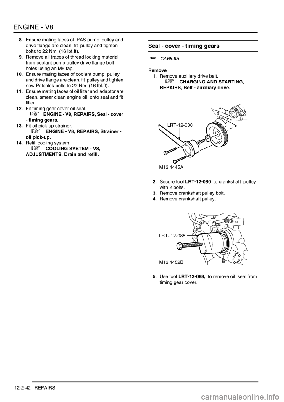
2.Secure tool LRT-12-080 to crankshaft pulley
with 2 bolts.
3.Remove crankshaft pulley bolt.
4.Remove crankshaft pulley.
5.Use tool LRT-12-088, to remove oil seal from
timing gear cover.
Page 446 of 1672

ENGINE MANAGEMENT SYSTEM - TD5
REPAIRS 18-1-53
Element - fuel filter
$% 19.25.07
Remove
1.Release turnbuckles and remove battery cover.
2.Disconnect battery earth lead.
3.Raise rear of vehicle.
WARNING: Do not work on or under a
vehicle supported only by a jack. Always
support the vehicle on safety stands.
4.Clean area around fuel filter.
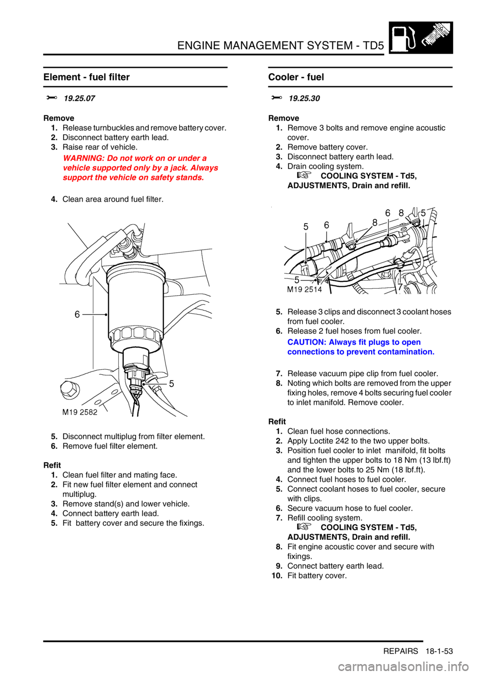
5.Disconnect multiplug from filter element.
6.Remove fuel filter element.
Refit
1.Clean fuel filter and mating face.
2.Fit new fuel filter element and connect
multiplug.
3.Remove stand(s) and lower vehicle.
4.Connect battery earth lead.
5.Fit battery cover and secure the fixings.
Cooler - fuel
$% 19.25.30
Remove
1.Remove 3 bolts and remove engine acoustic
cover.
2.Remove battery cover.
3.Disconnect battery earth lead.
4.Drain cooling system.
+ COOLING SYSTEM - Td5,
ADJUSTMENTS, Drain and refill.
5.Release 3 clips and disconnect 3 coolant hoses
from fuel cooler.
6.Release 2 fuel hoses from fuel cooler.
CAUTION: Always fit plugs to open
connections to prevent contamination.
7.Release vacuum pipe clip from fuel cooler.
8.Noting which bolts are removed from the upper
fixing holes, remove 4 bolts securing fuel cooler
to inlet manifold. Remove cooler.
Refit
1.Clean fuel hose connections.
2.Apply Loctite 242 to the two upper bolts.
3.Position fuel cooler to inlet manifold, fit bolts
and tighten the upper bolts to 18 Nm (13 lbf.ft)
and the lower bolts to 25 Nm (18 lbf.ft).
4.Connect fuel hoses to fuel cooler.
5.Connect coolant hoses to fuel cooler, secure
with clips.
6.Secure vacuum hose to fuel cooler.
7.Refill cooling system.
+ COOLING SYSTEM - Td5,
ADJUSTMENTS, Drain and refill.
8.Fit engine acoustic cover and secure with
fixings.
9.Connect battery earth lead.
10.Fit battery cover.
Page 448 of 1672

ENGINE MANAGEMENT SYSTEM - TD5
REPAIRS 18-1-55
Turbocharger
$% 19.42.01
Remove
1.Remove 3 bolts and remove engine acoustic
cover.
2.Release fixings and remove battery cover.
3.Disconnect battery earth lead.
4.Remove cooling fan cover.
5.Remove 3 bolts and remove exhaust manifold
heat shield.
6.Release clip and disconnect breather hose
from camshaft cover.
7.Release clip and disconnect vacuum hose from
turbocharger wastegate.
8.Loosen clips and release air intake and outlet
hoses from turbocharger. 9.Remove turbocharger oil feed banjo bolt and
discard sealing washers.
10.Remove 2 bolts and release turbocharger oil
drain pipe and discard gasket.
11.Remove 3 nuts and release exhaust front pipe
from turbocharger and discard gasket.
12.Remove 3 nuts securing turbocharger to
exhaust manifold.
13. Remove turbocharger and discard gasket.
Refit
1.Clean turbocharger and exhaust manifold
mating faces.
2.Using a new gasket, fit turbocharger to exhaust
manifold and tighten nuts to 30 Nm (22 lbf.ft).
3.Using new gasket, align exhaust front pipe and
tighten nuts to 30 Nm (22 lbf.ft).
4.Using new gasket, align turbocharger drain
pipe and tighten bolts to 9 Nm (7 lbf.ft).
5.Fit banjo bolt to oil feed pipe using new sealing
washers and tighten to 25 Nm (18 lbf.ft)..
6.Position air hoses to turbocharger and tighten
clips.
7.Position and secure breather hose to camshaft
cover.
8.Position and secure vacuum hose to
turbocharger wastegate.
9.Position exhaust manifold heat shield and
tighten M6 bolts to 9 Nm (7 lbf.ft) and M8 bolt to
25 Nm (18 lbf.ft).
10.Fit fan cowl and secure fixings.
11.Fit acoustic cover and secure the fixings.
12.Connect battery earth lead.
13.Fit battery cover and secure fixings.
Page 454 of 1672

ENGINE MANAGEMENT SYSTEM - TD5
REPAIRS 18-1-61
Injectors
$% 19.60.12
Remove
1.Remove cooling fan.
+ COOLING SYSTEM - Td5, REPAIRS,
Fan - viscous.
2.Remove rocker shaft.
+ ENGINE - Td5, REPAIRS, Rocker
shaft assembly.
3.Position container to catch fuel spillage.
4.Disconnect quick release fuel hose connectors
from fuel connector block on cylinder head and
fuel cooler to drain fuel from cylinder head. 5.Disconnect 5 multiplugs from injectors.
6.Remove 5 Torx bolts securing injectors to
cylinder head.
7.Using LRT-12-154/1, remove injectors from
cylinder head. Collect retainers.
8.Using LRT-12-154/4, remove sealing washers
from injectors. Discard sealing washers.
9.Remove and discard 'O' rings from injectors.
10.Rotate engine manually until each cylinder
being worked on is at TDC, and remove excess
fuel from piston bowl using a syringe.
Page 562 of 1672

FUEL DELIVERY SYSTEM - TD5
REPAIRS 19-1-17
Tank - fuel
$% 19.55.01
Remove
1.Drain fuel tank.
+ FUEL DELIVERY SYSTEM - Td5,
ADJUSTMENTS, Fuel tank - drain.
2.Raise rear of vehicle.
WARNING: Do not work on or under a
vehicle supported only by a jack. Always
support the vehicle on safety stands.
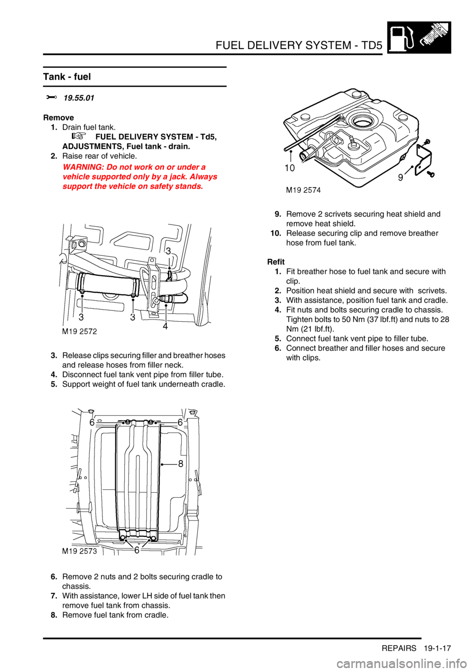
3.Release clips securing filler and breather hoses
and release hoses from filler neck.
4.Disconnect fuel tank vent pipe from filler tube.
5.Support weight of fuel tank underneath cradle.
6.Remove 2 nuts and 2 bolts securing cradle to
chassis.
7.With assistance, lower LH side of fuel tank then
remove fuel tank from chassis.
8.Remove fuel tank from cradle.9.Remove 2 scrivets securing heat shield and
remove heat shield.
10.Release securing clip and remove breather
hose from fuel tank.
Refit
1.Fit breather hose to fuel tank and secure with
clip.
2.Position heat shield and secure with scrivets.
3.With assistance, position fuel tank and cradle.
4.Fit nuts and bolts securing cradle to chassis.
Tighten bolts to 50 Nm (37 lbf.ft) and nuts to 28
Nm (21 lbf.ft).
5.Connect fuel tank vent pipe to filler tube.
6.Connect breather and filler hoses and secure
with clips.
Page 580 of 1672

FUEL DELIVERY SYSTEM - V8
REPAIRS 19-2-15
Tank - fuel
$% 19.55.01
Remove
1.Drain fuel tank.
+ FUEL DELIVERY SYSTEM - V8,
ADJUSTMENTS, Fuel tank - drain.
2.Raise rear of vehicle.
WARNING: Do not work on or under a
vehicle supported only by a jack. Always
support the vehicle on safety stands.
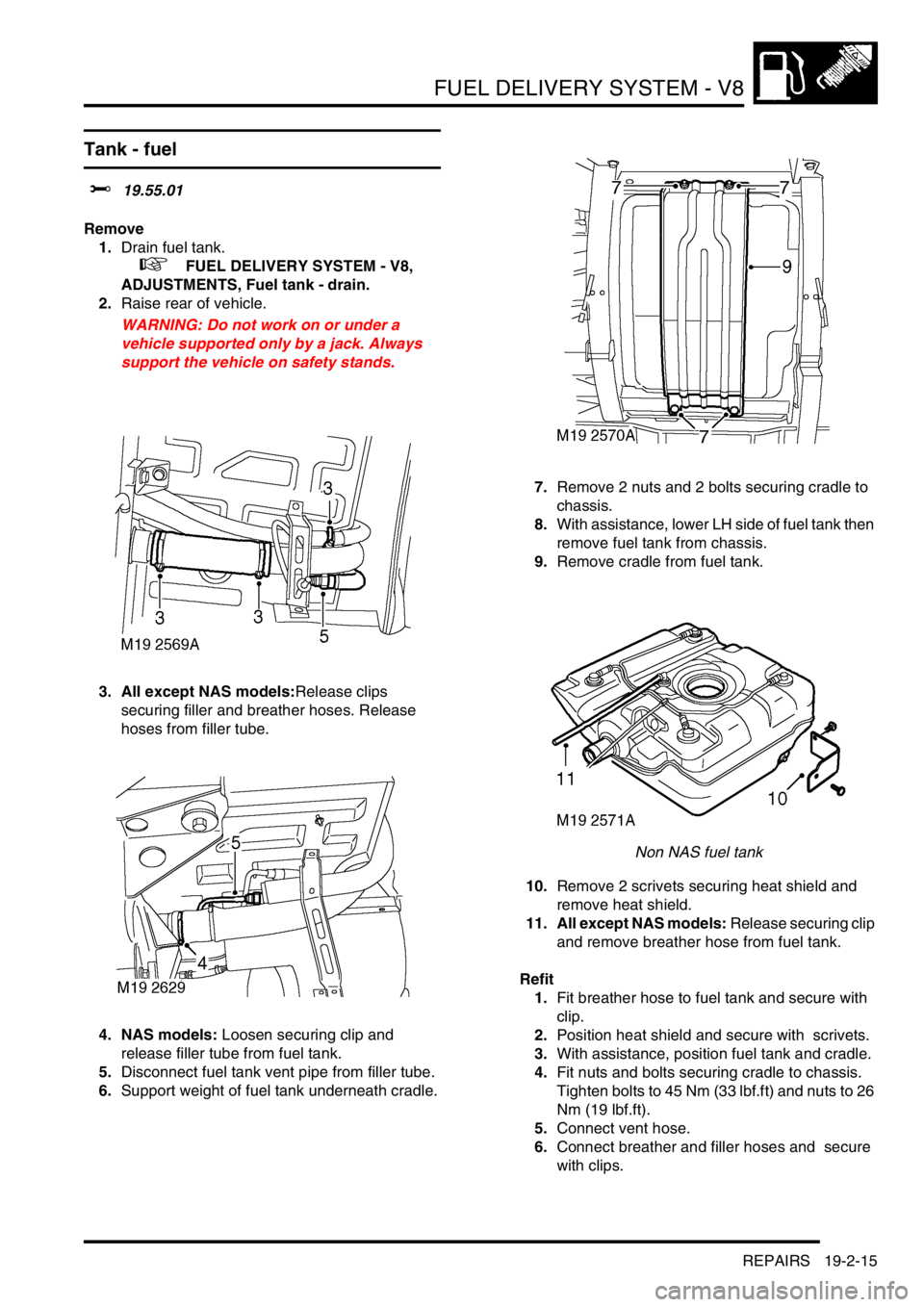
3. All except NAS models:Release clips
securing filler and breather hoses. Release
hoses from filler tube.
4. NAS models: Loosen securing clip and
release filler tube from fuel tank.
5.Disconnect fuel tank vent pipe from filler tube.
6.Support weight of fuel tank underneath cradle. 7.Remove 2 nuts and 2 bolts securing cradle to
chassis.
8.With assistance, lower LH side of fuel tank then
remove fuel tank from chassis.
9.Remove cradle from fuel tank.
Non NAS fuel tank
10.Remove 2 scrivets securing heat shield and
remove heat shield.
11. All except NAS models: Release securing clip
and remove breather hose from fuel tank.
Refit
1.Fit breather hose to fuel tank and secure with
clip.
2.Position heat shield and secure with scrivets.
3.With assistance, position fuel tank and cradle.
4.Fit nuts and bolts securing cradle to chassis.
Tighten bolts to 45 Nm (33 lbf.ft) and nuts to 26
Nm (19 lbf.ft).
5.Connect vent hose.
6.Connect breather and filler hoses and secure
with clips.
Page 598 of 1672

COOLING SYSTEM - TD5
REPAIRS 26-1-15
REPAIRS
Fan - viscous
$% 26.25.19
Remove
1.Release fixings and remove battery cover.
2.Disconnect battery earth lead.
3.Remove 3 bolts and remove engine acoustic
cover.
4.Remove upper fan cowl.
5.Remove viscous fan using tool LRT-12-093
and tool LRT-12-094.
RH thread.
Refit
1.Position viscous fan and tighten using tool
LRT-12-093 and tool LRT-12-094.
2.Fit upper fan cowl.
3. Fit engine acoustic cover and tighten bolts.
4.Connect battery earth lead.
5.Fit battery cover and secure with fixings.
Radiator
$% 26.40.01
Remove
1.Drain cooling system.
+ COOLING SYSTEM - Td5,
ADJUSTMENTS, Drain and refill.
2.Remove intercooler.
+ ENGINE MANAGEMENT SYSTEM -
Td5, REPAIRS, Intercooler.
3.Remove clip and disconnect bleed hose from
radiator.
4.Release clip and disconnect top hose from
radiator.
5.Release clip and disconnect bottom hose from
radiator.
6.Release clip and disconnect engine oil cooler
hose from radiator.
7.Release clip and disconnect fuel cooler hose
from radiator.
Page 601 of 1672

COOLING SYSTEM - TD5
26-1-18 REPAIRS
Pump - coolant
$% 26.50.01
Remove
1.Drain cooling system.
+ COOLING SYSTEM - Td5,
ADJUSTMENTS, Drain and refill.
2.Remove centrifuge.
+ ENGINE - Td5, REPAIRS, Gasket -
centrifuge oil drain pipe.
3.Release clip and disconnect hose from coolant
pump cover.
4.Remove 5 bolts securing coolant pump cover.
5.Remove cover and coolant pump from housing
and discard 'O' rings. Refit
1.Clean coolant pump housing and mating faces.
2.Fit new 'O' rings to coolant pump and cover.
3.Fit coolant pump and cover and tighten bolts
to 9 Nm (7 lbf.ft).
4.Connect hose to pump cover and secure with
clip.
5.Refit centrifuge.
+ ENGINE - Td5, REPAIRS, Gasket -
centrifuge oil drain pipe.
6.Refill cooling system.
+ COOLING SYSTEM - Td5,
ADJUSTMENTS, Drain and refill.
Page 609 of 1672

COOLING SYSTEM - V8
26-2-8 DESCRIPTION AND OPERATION
Pipes and hoses
The coolant circuit comprises flexible hoses and metal formed pipes which direct coolant into and out of the engine,
radiator and heater matrix. Plastic pipes are used for the bleed and overflow pipes to the expansion tank.
A bleed screw is installed in the radiator top hose and is used to bleed air during system filling. A drain plug is fitted
to each cylinder bank in the cylinder block. These are used to drain the block of coolant.
Coolant pump
1Pulley flange
2Body
3Impeller
4Gallery
5Inlet connection
The coolant pump is attached to the front of the cylinder block with nine bolts and sealed between the pump housing
and the cylinder block with a gasket. The pump comprises a shaft which passes through an alloy housing. The outer
end of the shaft has a flange which allows for the attachment of the pump drive pulley which is secured with three
bolts. The drive pulley is driven by the grooved auxiliary drive belt and rotates at the same speed as the crankshaft.
The inner end of the shaft is fitted with an impeller which draws coolant from the thermostat housing and circulates it
through the galleries in the cylinder block and through the heater matrix.
The shaft is supported on bearings in the housing which are packed with grease and sealed for life. A seal is
positioned in the housing to further protect the bearings from the ingress of coolant. The seal is manufactured from a
synthetic material which will allow for expansion of the casing when hot coolant is present.
The cast alloy housing has a hose connection which provides the attachment for the coolant pump feed hose. The
cast housing connects with galleries in the cylinder block and distributes coolant from the pump impeller into the
galleries and water jackets.
Page 618 of 1672

COOLING SYSTEM - V8
REPAIRS 26-2-17
16.Remove radiator assembly.
17.Release clip and remove bottom hose from
radiator.
18.Remove 2 bolts and remove extension
brackets from radiator.
19.Remove 2 captive nuts from radiator.
20.Remove 2 screws and remove gearbox oil
cooler from radiator.
21. If fitted: Remove 2 screws and remove engine
oil cooler from radiator.
22.Remove 2 rubber mountings from radiator.
23.Remove sealing strip from bottom of radiator.
24.Remove 2 cowl retaining clips from radiator. Refit
1.Fit cowl retaining clips to radiator.
2.Fit sealing strip to radiator.
3.Fit rubber mountings to radiator.
4.Fit gearbox oil cooler to radiator and secure
with screws.
5. If fitted: Fit engine oil cooler to radiator and
secure with screws.
6.Fit captive nuts to radiator.
7.Fit extension brackets to radiator and secure
with bolts.
8.Fit bottom hose to radiator and secure with clip.
9.Fit radiator and engage lower mountings in
chassis.
10.Ensure connections are clean, then secure
hoses to oil coolers.
11.Fit air conditioning condenser brackets and
secure with screws.
12.Fit radiator upper mounting brackets and
secure with bolts.
13.Fit LH horn and secure with nut.
14.Fit air deflectors and secure with scrivets.
15.Connect multiplug of gearbox oil temperature
sensor.
16.Fit front grille.
+ EXTERIOR FITTINGS, REPAIRS,
Grille - front - up to 03MY.
17.Connect bottom hose to thermostat housing
and secure with clip.
18.Connect top hose to radiator and secure with
clip.
19.Connect bleed hose to radiator and fit clip.
20.Fit lower fan cowl and secure with screws.
21.Fit viscous fan.
+ COOLING SYSTEM - V8, REPAIRS,
Fan - viscous.
22.Top up gearbox oil.
23.Top up engine oil.
24.Refill cooling system.
+ COOLING SYSTEM - V8,
ADJUSTMENTS, Drain and refill.