LAND ROVER DISCOVERY 2002 Workshop Manual
Manufacturer: LAND ROVER, Model Year: 2002, Model line: DISCOVERY, Model: LAND ROVER DISCOVERY 2002Pages: 1672, PDF Size: 46.1 MB
Page 711 of 1672

MANUAL GEARBOX - R380
37-28 OVERHAUL
6.Fit layshaft bearing track to front cover.
7.Using tool LRT-99-002 and a suitable mandrel,
fit pilot bearing outer track to input shaft.
8.Clean synchroniser hubs, gears and bearings.
9.Position output shaft in protected vice jaws,
output end upwards.
10.Fit 2nd gear bearing, 2nd gear and
synchromesh baulk rings onto output shaft.
11.Position 1st / 2nd synchroniser hub onto output
shaft. Ensure that baulk rings are correctly
located in hub.
12.Position 1st gear synchromesh baulk rings,
needle roller bearing, 1st gear and bearing
collar onto output shaft. Ensure baulk rings are
correctly located in hub.
13.Remove output shaft from vice.
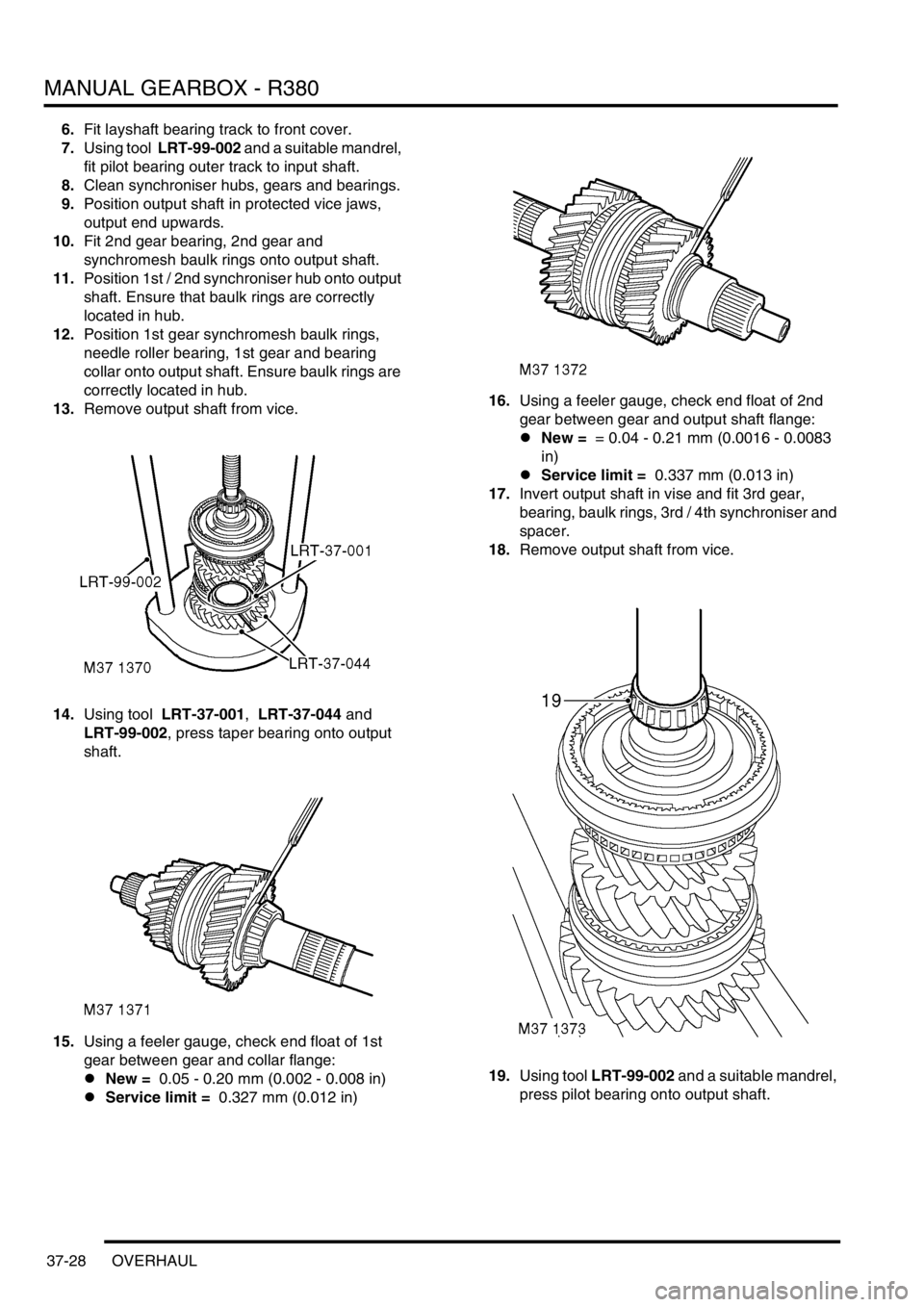
14.Using tool LRT-37-001, LRT-37-044 and
LRT-99-002, press taper bearing onto output
shaft.
15.Using a feeler gauge, check end float of 1st
gear between gear and collar flange:
lNew = 0.05 - 0.20 mm (0.002 - 0.008 in)
lService limit = 0.327 mm (0.012 in) 16.Using a feeler gauge, check end float of 2nd
gear between gear and output shaft flange:
lNew = = 0.04 - 0.21 mm (0.0016 - 0.0083
in)
lService limit = 0.337 mm (0.013 in)
17.Invert output shaft in vise and fit 3rd gear,
bearing, baulk rings, 3rd / 4th synchroniser and
spacer.
18.Remove output shaft from vice.
19.Using tool LRT-99-002 and a suitable mandrel,
press pilot bearing onto output shaft.
Page 712 of 1672

MANUAL GEARBOX - R380
OVERHAUL 37-29
20.Check end float of 3rd gear between gear and
flange on output shaft:
lNew = 0.11 - 0.21 mm (0.004 - 0.0083 in)
lService limit = 0.337 mm (0.013 in)
21.Check output shaft and layshaft end float as
follows.
22.The end float setting for both shafts is:
lNew = 0.00 to 0.05 mm (0.0 to - 0.002 in)
lService limit = 0.05 mm (0.002 in)
23.Fit front cover to gearbox case without the oil
seal and tighten bolts by diagonal selection to
25 Nm (18 lbf.ft).
24.Position in vice with front cover facing
downwards.
25.Fit input shaft to gearbox case less 4th gear
baulk ring.
26.Fit output shaft assembly to input shaft.
27.Fit output shaft bearing track and shim to centre
plate.
28.Fit centre plate to gearbox case and secure
using 8 slave bolts.
29.Rotate output shaft to settle bearings.
30.Fit a suitably large ball bearing into end of
output shaft.
31.Position a suitable DTI and zero probe on ball
bearing.
32.Lift output shaft and note DTI reading.
33.If reading is incorrect, dismantle and fit shim to
give correct end float.
34.Repeat above procedure.
35.Repeat procedure for layshaft end float.
36.Remove and discard 6 bolts and remove
gearbox front cover.
37.Fit gearbox selector fork - set.
+ MANUAL GEARBOX - R380,
OVERHAUL, Fork - set - selector shaft.
38.Fit gearbox front cover.
+ MANUAL GEARBOX - R380,
OVERHAUL, Cover - front.
Synchroniser - gearbox - set
$% 37.20.07
Disassembly
1.Remove gearbox selector fork set.
+ MANUAL GEARBOX - R380,
OVERHAUL, Fork - set - selector shaft.
2.Using tool LRT-99-002 and support bars
under 1st gear, press output shaft bearing from
output shaft.
3.Remove 1st gear, bearing collar, needle roller
bearing and synchromesh rings.
4.Noting its fitted position, remove 1st / 2nd gear
synchroniser hub, 2nd gear synchromesh
rings, 2nd gear and needle roller bearing.
Page 713 of 1672

MANUAL GEARBOX - R380
37-30 OVERHAUL
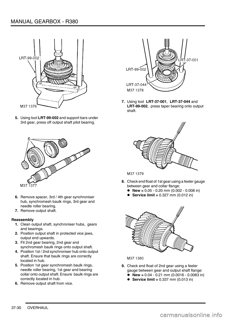
5.Using tool LRT-99-002 and support bars under
3rd gear, press off output shaft pilot bearing.
6.Remove spacer, 3rd / 4th gear synchroniser
hub, synchromesh baulk rings, 3rd gear and
needle roller bearing.
7.Remove output shaft.
Reassembly
1.Clean output shaft, synchroniser hubs, gears
and bearings.
2.Position output shaft in protected vice jaws,
output end upwards.
3.Fit 2nd gear bearing, 2nd gear and
synchromesh baulk rings onto output shaft.
4.Position 1st / 2nd synchroniser hub onto output
shaft. Ensure that baulk rings are correctly
located in hub.
5.Position 1st gear synchromesh baulk rings,
needle roller bearing, 1st gear and bearing
collar onto output shaft. Ensure baulk rings are
correctly located in hub.
6.Remove output shaft from vice. 7.Using tool LRT-37-001, LRT-37-044 and
LRT-99-002, press taper bearing onto output
shaft.
8.Check end float of 1st gear using a feeler gauge
between gear and collar flange:
lNew = 0.05 - 0.20 mm (0.002 - 0.008 in)
lService limit = 0.327 mm (0.012 in)
9.Check end float of 2nd gear using a feeler
gauge between gear and output shaft flange:
lNew = 0.04 - 0.21 mm (0.0016 - 0.0083 in)
lService limit = 0.337 mm (0.013 in)
Page 714 of 1672

MANUAL GEARBOX - R380
OVERHAUL 37-31
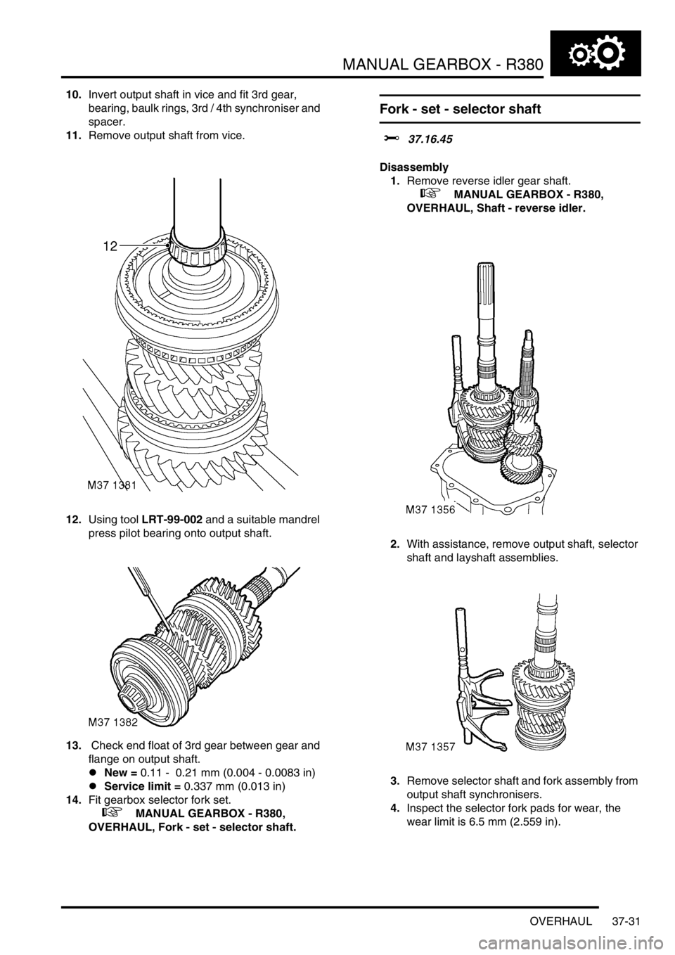
10.Invert output shaft in vice and fit 3rd gear,
bearing, baulk rings, 3rd / 4th synchroniser and
spacer.
11.Remove output shaft from vice.
12.Using tool LRT-99-002 and a suitable mandrel
press pilot bearing onto output shaft.
13. Check end float of 3rd gear between gear and
flange on output shaft.
lNew = 0.11 - 0.21 mm (0.004 - 0.0083 in)
lService limit = 0.337 mm (0.013 in)
14.Fit gearbox selector fork set.
+ MANUAL GEARBOX - R380,
OVERHAUL, Fork - set - selector shaft.
Fork - set - selector shaft
$% 37.16.45
Disassembly
1.Remove reverse idler gear shaft.
+ MANUAL GEARBOX - R380,
OVERHAUL, Shaft - reverse idler.
2.With assistance, remove output shaft, selector
shaft and layshaft assemblies.
3.Remove selector shaft and fork assembly from
output shaft synchronisers.
4.Inspect the selector fork pads for wear, the
wear limit is 6.5 mm (2.559 in).
Page 715 of 1672

MANUAL GEARBOX - R380
37-32 OVERHAUL
Reassembly
1.Clean selector shaft, forks and locations on
synchronisers.
2.Lubricate forks and shaft with clean gear oil.
3.Position selector shaft assembly to output shaft
synchronisers.
4.With assistance, fit output shaft and layshaft
assembly into gearbox case.
5.Fit reverse idler gear shaft.
+ MANUAL GEARBOX - R380,
OVERHAUL, Shaft - reverse idler.
Shaft - gearbox - input
$% 37.20.16
Disassembly
1.Remove gearbox front cover.
+ MANUAL GEARBOX - R380,
OVERHAUL, Cover - front.
2.Remove reverse idler gear shaft.
+ MANUAL GEARBOX - R380,
OVERHAUL, Shaft - reverse idler.
3.With assistance, remove output shaft, selector
shaft and layshaft as an assembly. Remove
selector shaft and fork.
4.Remove input shaft from gearbox case.
Page 716 of 1672

MANUAL GEARBOX - R380
OVERHAUL 37-33
5.Using tool LRT-37-004, and LRT-99-004,
remove pilot bearing track from input shaft.
6.Invert output shaft and using tool LRT- 99-002
and support bars under 3rd gear, press off pilot
bearing.7.Using tool LRT-37-043 and LRT-99-002,
remove taper roller bearing from input shaft.
8.Using a suitable soft metal drift, remove
bearing outer track from front cover.
9.Remove and discard input shaft oil seal from
front cover.
Page 717 of 1672

MANUAL GEARBOX - R380
37-34 OVERHAUL
Reassembly
1.Clean input shaft and bearing/oil seal recess in
front cover.
2.Lubricate a new input shaft oil seal with
gearbox oil.
3.Fit oil seal using a suitable mandrel.
4.Using a press and a suitable mandrel, fit
bearing outer track in front cover.
5.Using a press and a suitable mandrel, fit pilot
bearing outer track to input shaft.
6.Using tool LRT-37-043, LRT-37–043/2 and
LRT-99-002, fit new taper bearing to input
shaft.7.Using tool LRT-99-002 and a suitable mandrel,
press new pilot bearing onto output shaft.
8.Position input shaft to gearbox case.
9.With assistance, fit output shaft and layshaft
assembly into gearbox case.
10.Fit reverse idler gear shaft.
+ MANUAL GEARBOX - R380,
OVERHAUL, Shaft - reverse idler.
11.Fit gearbox front cover.
+ MANUAL GEARBOX - R380,
OVERHAUL, Cover - front.
Page 718 of 1672

MANUAL GEARBOX - R380
OVERHAUL 37-35
Extension - gearbox rear
$% 37.12.01
Disassembly
1.Remove 4 bolts and remove gear selector
housing.
2.Using tools LRT-37-009, LRT-37-001/2 and
LRT-37-010 , remove output shaft oil seal
collar.3.Remove bolt securing interlock spool retainer
and discard 'O' ring.
4.Noting fitted position of 2 longest bolts, remove
10 bolts securing extension housing to
gearbox.
5.Remove extension housing from gearbox
centre plate.
Page 719 of 1672

MANUAL GEARBOX - R380
37-36 OVERHAUL
6.Fit 2 off 8x35 mm slave bolts to secure centre
plate to gearbox casing.
7.Remove 3 Torx screws, remove oil pump and
discard 'O' ring.
8.Drift out layshaft support bearing.
9.Remove and discard output shaft rear oil seal.
10.Remove oil pick-up pipe.
11.Drift out output shaft support bearing and oil
pick-up ring.
12.Remove reverse inhibitor shaft, cam and
spring. 13.Remove 2 bolts and remove gate plate.
14.Remove reverse light switch and discard
sealing washer.
15.Remove 2 bolts, remove oil cooler by-pass and
discard 'O' rings.
Reassembly
1.Clean extension housing and mating faces.
2.Clean oil cooler by-pass.
3.Using new 'O' rings, fit oil cooler by-pass and
tighten bolts to 15 Nm (11 lbf.ft).
4.Using new sealing washer, fit reverse light
switch and tighten to 24 Nm (17 lbf.ft).
5.Fit reverse inhibitor spring and cam.
6.Clean threads of reverse inhibitor shaft and
gate plate bolts.
7.Apply Loctite 290 to threads of reverse inhibitor
shaft, fit and tighten shaft.
8.Apply Loctite 290 to threads of gate plate bolts.
9.Position gate plate and tighten bolts to 15 Nm
(11 lbf.ft).
10.Fit output shaft support bearing and oil pick-up
ring. Align tag with centre of drain slot.
11.Fit layshaft support bearing.
12.Fit new output shaft oil seal using tool LRT-37-
014.
Page 720 of 1672

MANUAL GEARBOX - R380
OVERHAUL 37-37
13.Fit oil pick-up pipe with the off-set uppermost.
14.Lubricate oil pump recess with gearbox oil.
15.Lubricate a new 'O' ring with gearbox oil and fit
to oil pump.
16.Locate oil pump in extension housing with word
'TOP' towards top of housing.
17.Align oil pump fixing screw holes and tap pump
lightly around edges until it is fully in recess.
Do not attempt to pull pump into recess
using fixing screws.
18.Fit Torx screws and tighten to 6 Nm (4.5 lbf.ft).
19.Remove 2 slave bolts securing centre plate to
gearbox casing.
20.Apply sealant, Part No. STC 3254 to gearbox
casing face.
21.Position extension housing, align oil pump drive
with layshaft.
22.Clean extension housing bolt threads.
23.Apply Loctite 290 to threads of extension
housing bolts, fit bolts ensuring 2 longest bolts
are in their original positions and tighten by
diagonal selection to 25 Nm (18 lbf.ft).
24.Using new 'O' ring, fit interlock spool retainer
and tighten bolt to 8 Nm (6 lbf.ft).
25.Using tool LRT-37-015 and LRT-37-021, fit oil
seal collar.
26.Clean gear selector selector housing and
mating face.
27.Apply sealant, Part No. STC 3254 to gear
selector housing face.
28.Position gear selector housing and tighten
bolts to 25 Nm (18 lbf.ft).
Pump - gearbox oil
$% 37.12.47
Disassembly
1.Remove gearbox extension.
+ MANUAL GEARBOX - R380,
OVERHAUL, Extension - gearbox rear.
2.Remove 3 Torx screws, remove oil pump and
discard 'O' ring.
Reassembly
1.Clean oil pump recess in extension housing,
ensure screw holes are clean and dry.
2.Lubricate oil pump recess in housing with
gearbox oil.
3.Lubricate a new 'O' ring with gearbox oil and fit
to oil pump.
4.Locate oil pump in extension housing with word
'TOP' towards top of housing.
5.Align fixing screw holes and tap pump lightly
around edges until pump is fully in housing. Do
not pull pump into housing by tightening
screws.
6.Fit Torx screws and tighten to 6 Nm (4.5 lbf.ft).
7.Fit gearbox extension.
+ MANUAL GEARBOX - R380,
OVERHAUL, Extension - gearbox rear.