ECU LAND ROVER DISCOVERY 2002 Workshop Manual
[x] Cancel search | Manufacturer: LAND ROVER, Model Year: 2002, Model line: DISCOVERY, Model: LAND ROVER DISCOVERY 2002Pages: 1672, PDF Size: 46.1 MB
Page 1626 of 1672

NAVIGATION SYSTEM
REPAIRS 87-11
REPAIRS
Interface electronic control unit (ECU) -
remote control
$% 86.53.15
Remove
1.Remove navigation display unit.
+ NAVIGATION SYSTEM, REPAIRS,
Display unit.
2.Remove automatic temperature control unit.
+ AIR CONDITIONING, REPAIRS, ECU
- air temperature control.
3.Remove 2 nuts securing interface carrier
bracket, carefully pull bracket out of fascia.
4.Release interface ECU from bracket,
disconnect multiplug and remove ECU.Refit
1.Secure interface ECU in bracket and connect
multiplug.
2.Carefully position carrier bracket in fascia,
secure with nuts and tighten to 10 Nm (7 lbf.ft).
3.Fit automatic temperature control unit.
+ AIR CONDITIONING, REPAIRS, ECU
- air temperature control.
4.Fit navigation display unit.
+ NAVIGATION SYSTEM, REPAIRS,
Display unit.
M86 5760
M86 5762
Page 1627 of 1672

NAVIGATION SYSTEM
87-12 REPAIRS
Display unit
$% 86.53.20
Remove
1.Fit tool LRT-86-009 into slots ensuring correct
handed key is in correct slot.
The tools are stamped either 'TOP L' or 'TOP
R', ensure the stamping is facing upwards
when removing the unit.
2.Pull display unit from fascia.
3.Disconnect 3 multiplugs and 2 coax cables
from display unit and remove unit.
4.Push display unit retaining clips inwards and
remove keys.Refit
1.Position display unit to fascia, connect
multiplugs and coax cables.
2.Push display unit into fascia until retaining clips
engage.
3.Enter security code and check system is
operational.
M86 5824
M86 5825
Page 1630 of 1672

INSTRUMENTS
DESCRIPTION AND OPERATION 88-3
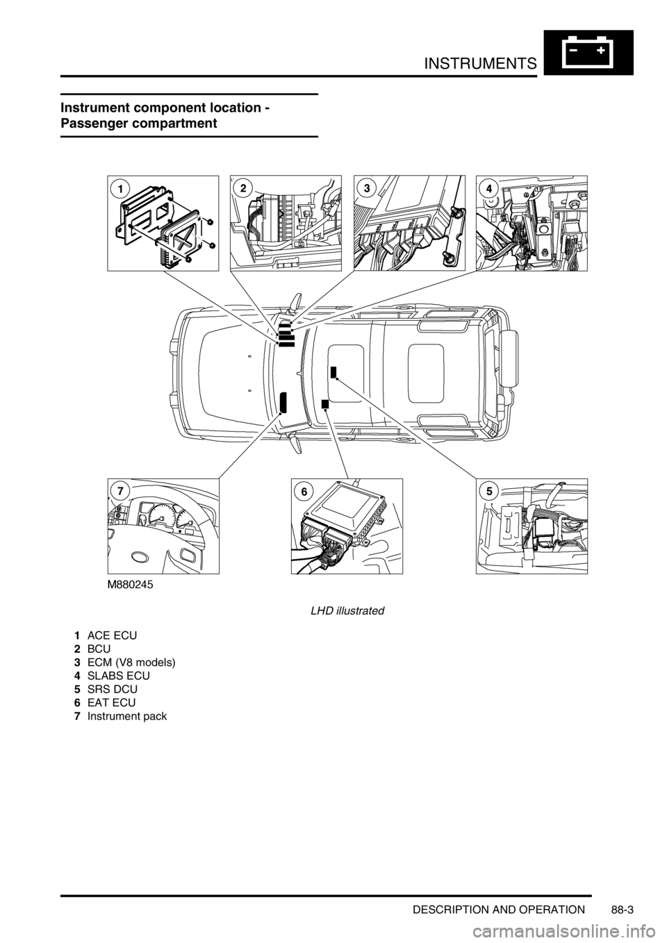
Instrument component location -
Passenger compartment
LHD illustrated
1ACE ECU
2BCU
3ECM (V8 models)
4SLABS ECU
5SRS DCU
6EAT ECU
7Instrument pack
Page 1631 of 1672

INSTRUMENTS
88-4 DESCRIPTION AND OPERATION
Instrument block diagram
1Instrument pack
2ECM
3Brake fluid level switch
4Parking brake switch
5Oil pressure switch
6Alternator
7Fuel tank sender unit
8Water in fuel filter sensor
9Transmission temperature sensor
10Differential lock switch - vehicles up to 03
model year or Differential lock switches -
vehicles from 03 model year11Audible warning speaker
12SRS DCU
13SLABS ECU
14BCU
15ACE ECU
16EAT ECU
17Diagnostic connector
18Serial communications link
Page 1633 of 1672

INSTRUMENTS
88-6 DESCRIPTION AND OPERATION
The third warning lamp pack is located in the top right-hand side of the instrument pack and contains the following
warning lamps:
lSRS warning lamp.
lSLS off road mode warning lamp.
lTrailer warning lamp.
lGlow plug warning lamp.
lWater in fuel filter warning lamp.
lSeat belt warning lamp.
lTransmission high temperature warning lamp.
The fourth warning lamp pack is located underneath the tachometer of the instrument pack contains the following
warning lamps:
lOil pressure warning lamp.
lAlternator charge warning lamp.
lHDC fault warning lamp.
lSelf Levelling Suspension (SLS) warning lamp.
lActive Cornering Enhancement (ACE) warning lamp.
lGearbox manual/sport mode warning lamps.
The serial communication link is used to allow information to travel to and from the instrument pack, and it provides
the ability to configure the instrument pack to a specific market. It also allows the instrument pack to be controlled by
TestBook for diagnostics.
There are five market specific variants of the instrument pack:
lUnited Kingdom (UK).
lNorth American Specification (NAS).
lCanada.
lAustralia.
lRest Of the World (ROW), Gulf and Japan.
The main difference between the five markets is that the speedometer will indicate road speed in mph as major figures
and km/h as minor figures, km/h as major figures and mph as minor figures or km/h only.
When TestBook is used to diagnose the instrument pack it demands each of the dials and warning lamps to operate
in-turn so a visual check of their operation can be made.
CAUTION: The instrument pack must not be stored on its face side at any time. This is because the dials have
damping fluid within them to ensure smooth operation of the dials' indicator needles. This fluid will leak out.
Speedometer
The speedometer informs the driver of the current vehicle road speed. It has a Liquid Crystal Display (LCD) to show
odometer, trip meter and, on automatic gearbox models, the selected gear. The speedometer will not show speeds
of less than 1.5 mph (2.5 km/h).
There are three different market configurations:
lNAS and UK = mph as major figures km/h as minor figures.
lCanada = km/h as major figures mph as minor figures.
lROW and Australia = km/h only.
The Self Levelling and Anti-Lock Brake System (SLABS) ECU provides the signal input for the road speed. The signal
is at 8000 pulses per mile (1.6 kilometres).
Page 1634 of 1672

INSTRUMENTS
DESCRIPTION AND OPERATION 88-7
LCD odometer/trip meter
The LCD has 3 different display elements:
lOdometer.
lTrip meter.
lSelected gear (on vehicles with automatic gearboxes).
The odometer displays units in either miles or kilometres. It has a range from 0 to 999,999 units, only full units are
displayed irrespective of the type of units selected, the display will stop at 999,999 units. TestBook can be used to
reset the odometer. This is allowed only once and must be carried out before 150 miles (240 km) from new, after this
distance the feature is disabled. The odometer may lose up to one km (0.6 miles) when the battery is reconnected,
this is due to the software incorporated into the instrument pack to prevent anyone tampering with the odometer
reading.
The trip meter displays units in either miles or kilometres and has a range of 0.0 to 999.9 units. The display rolls over
from 999.9 to 0.0 units. Units down to one tenth of a mile or one tenth of a kilometre are displayed. The trip meter
displays 0.0 when the battery is reconnected or charged from a discharged state.
A push button located next to the LCD is utilised to reset the trip meter to zero and to change the units from miles to
kilometres. Pressing the button for less than 2 seconds allows the display to reset to zero. Pressing the button for
more than 2 seconds changes the units from miles to kilometres and vice versa. The units will only change for UK,
NAS and Canadian market vehicles.
The selected gear displays when the automatic gearbox is in park, reverse, neutral, drive 3,2,1, by using the letters
or numbers PRND321 in the display.
The data input for the LCD odometer/trip meter is from the SLABS ECU for the distance input and from the BCU for
the gear position. The instrument pack provides the earth path to illuminate the gear position warning lamp.
If a replacement instrument pack is required TestBook must be used to retrieve the odometer reading, so that when
the new instrument pack is fitted the odometer reading can be programmed in.
Page 1639 of 1672

INSTRUMENTS
88-12 DESCRIPTION AND OPERATION
Malfunction Indicator Lamp (MIL)/ SERVICE ENGINE SOON warning lamp
The MIL/service engine soon warning lamp within the instrument pack utilises an amber LED and a clear legend. If
an emission related fault is detected by the engine management system or, on automatic gearbox models, the EAT
ECU, the ECM will illuminate the LED providing the driver with a visible warning.
The warning lamp will illuminate whenever the vehicle is driven until the fault is repaired, and the ECM fault code
memory is cleared using TestBook.
When the ignition is switch on the ECM carries out a self-test function of the lamp. The lamp will illuminate for 3
seconds then extinguish if no faults exist. If a fault is present the lamp will be extinguished for 1 second before
illuminating again to indicate a fault exists.
There are two configurations of the legend for the warning lamp:
lNAS and Canada = SERVICE ENGINE SOON text.
lAll other markets = MIL SAE J1930 symbol.
The power input for the LED is supplied by the instrument pack via fuse 27. The ECM provides a voltage to the
instrument pack Central Processing Unit (CPU) to control the warning lamp:
l< 1.8 volts = warning lamp on.
l> 7.7 volts = warning lamp off.
Page 1641 of 1672

INSTRUMENTS
88-14 DESCRIPTION AND OPERATION
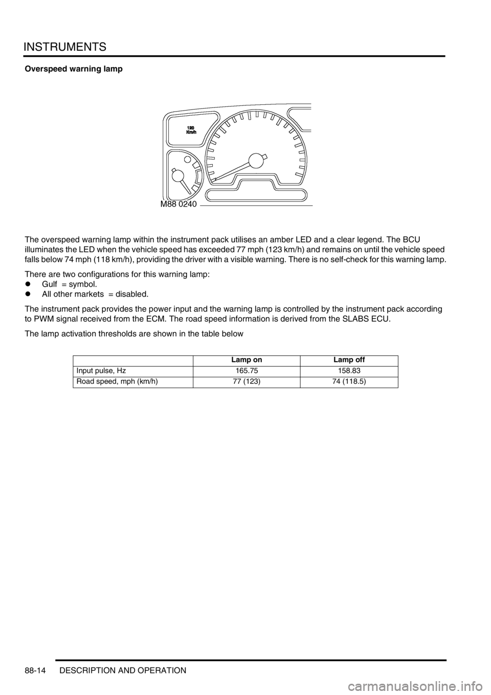
Overspeed warning lamp
The overspeed warning lamp within the instrument pack utilises an amber LED and a clear legend. The BCU
illuminates the LED when the vehicle speed has exceeded 77 mph (123 km/h) and remains on until the vehicle speed
falls below 74 mph (118 km/h), providing the driver with a visible warning. There is no self-check for this warning lamp.
There are two configurations for this warning lamp:
lGulf = symbol.
lAll other markets = disabled.
The instrument pack provides the power input and the warning lamp is controlled by the instrument pack according
to PWM signal received from the ECM. The road speed information is derived from the SLABS ECU.
The lamp activation thresholds are shown in the table below
Lamp on Lamp off
Input pulse, Hz 165.75 158.83
Road speed, mph (km/h) 77 (123) 74 (118.5)
Page 1645 of 1672

INSTRUMENTS
88-18 DESCRIPTION AND OPERATION
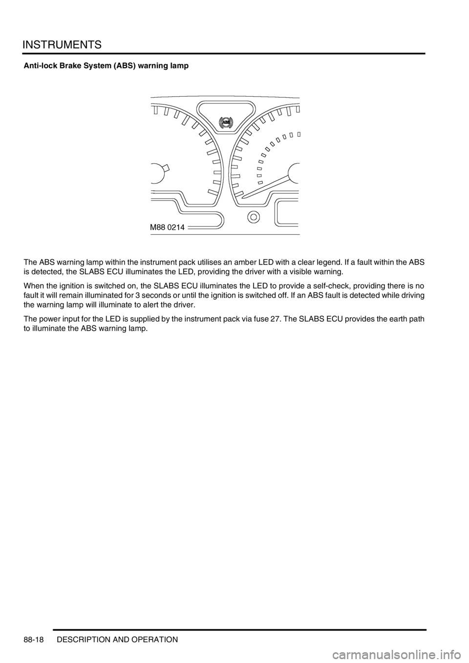
Anti-lock Brake System (ABS) warning lamp
The ABS warning lamp within the instrument pack utilises an amber LED with a clear legend. If a fault within the ABS
is detected, the SLABS ECU illuminates the LED, providing the driver with a visible warning.
When the ignition is switched on, the SLABS ECU illuminates the LED to provide a self-check, providing there is no
fault it will remain illuminated for 3 seconds or until the ignition is switched off. If an ABS fault is detected while driving
the warning lamp will illuminate to alert the driver.
The power input for the LED is supplied by the instrument pack via fuse 27. The SLABS ECU provides the earth path
to illuminate the ABS warning lamp.
Page 1648 of 1672

INSTRUMENTS
DESCRIPTION AND OPERATION 88-21
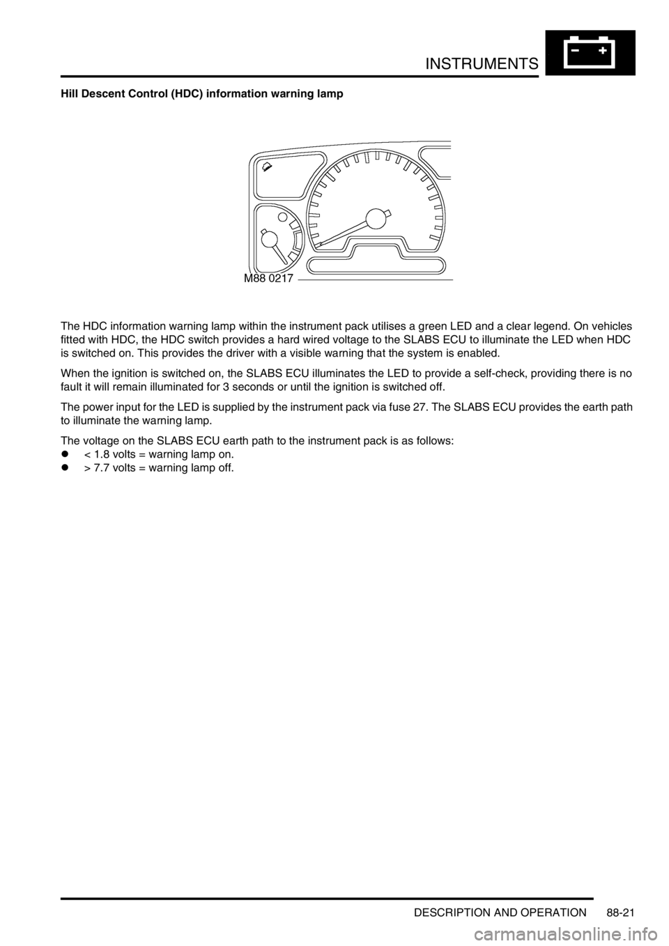
Hill Descent Control (HDC) information warning lamp
The HDC information warning lamp within the instrument pack utilises a green LED and a clear legend. On vehicles
fitted with HDC, the HDC switch provides a hard wired voltage to the SLABS ECU to illuminate the LED when HDC
is switched on. This provides the driver with a visible warning that the system is enabled.
When the ignition is switched on, the SLABS ECU illuminates the LED to provide a self-check, providing there is no
fault it will remain illuminated for 3 seconds or until the ignition is switched off.
The power input for the LED is supplied by the instrument pack via fuse 27. The SLABS ECU provides the earth path
to illuminate the warning lamp.
The voltage on the SLABS ECU earth path to the instrument pack is as follows:
l< 1.8 volts = warning lamp on.
l> 7.7 volts = warning lamp off.