ECU LAND ROVER DISCOVERY 2002 Workshop Manual
[x] Cancel search | Manufacturer: LAND ROVER, Model Year: 2002, Model line: DISCOVERY, Model: LAND ROVER DISCOVERY 2002Pages: 1672, PDF Size: 46.1 MB
Page 1609 of 1672

DRIVING AIDS
86-8-10 DESCRIPTION AND OPERATION
Operation
PDC System Operation
When the ignition switch is in position II and reverse gear is selected, the PDC sensors are automatically activated.
The PDC ECU only activates the system if reverse is selected for more than 1 second. This avoids nuisance audible
warnings when the gear selector lever is being moved between Drive and Park on vehicles with automatic
transmission.
When the system is activated, the PDC ECU illuminates the indicator LED in the PDC switch, switches on the
ultrasonic sensors and generates a single chime on the PDC sounder to indicate the system is active. If an object is
range of the sensors when the system is activated, a series of audible warnings are emitted by the PDC sounder
immediately.
If PDC operation is not required, it can be suspended temporarily by pressing the PDC switch. When reverse is
deselected and subsequently reselected, PDC will automatically become active again.
PDC can also be manually selected when not in reverse gear by pressing the PDC switch. A second press of the
switch is required to turn off the PDC or the PDC will be deactivated if reverse is selected and then deselected.
Sensor Operation
The PDC ECU processes the distance readings from the ultrasonic sensors to determine if there are any objects
within the detection areas. If there are no objects in the detection areas, there are no further audible warnings. If an
object is detected, repeated audible warnings are produced on the PDC sounder.
The maximum detection range is 1800 mm (70 in). When an object is detected, the time delay between the audible
warning tones decreases as the distance between the detected object and the vehicle decreases until, at
approximately 450 mm (17 in), the audible warning tone is continuous.
After the initial detection of an object, if there is no decrease in the distance between an object and the central sensors,
the time delay between the audible warnings remains constant. If an object is detected by one of the corner sensors
only, the audible warnings stop after about 5 seconds if there is no change in the distance between the object and the
corner sensor.
Page 1610 of 1672

DRIVING AIDS
DESCRIPTION AND OPERATION 86-8-11
Park Distance Control Detection Areas
aIntermittent Warning Tone
bContinuous Warning Tone
Detection Calculation
When operating in the combined transmitter and receiver mode, the sensor outputs a number ultrasonic pulses and
receives the reflected echo signal. The ECU amplifies the received echo signals and compares them with a
preprogrammed threshold to calculate the distance to the object. This is achieved by determining the elapsed time
between the transmission and reception of the ultrasonic signal.
When operating in receiver mode, the sensor receives echo signals transmitted by an adjacent sensor. This mode is
used to improve the accuracy of the system.
The detection cycle consists of the ECU operating one sensor in the combined transmitter and receiver mode and
transmitting a number of ultrasonic pulses. The ECU then switches the transmitting sensor and the adjacent sensor(s)
to receiver mode. After a short time delay, this sequence is repeated using a different sensor to transmit the ultrasonic
pulse and continues until all four sensors have output an ultrasonic signal. This sequence is completed in 100ms. The
ECU uses several measurements of the same sensors to remove errors from the calculation.
If the object is directly behind a sensor, the distance is calculated using the time between the transmission and
reception of the signal. If the object is positioned between two sensors, the ECU uses both signals to determine the
correct distance using triangulation.
To perform the triangulation calculation, the ECU must know the distance between the individual sensors in the
bumper. This information is stored in the ECU memory. From the received distance from each sensor and using the
known distance between adjacent sensors, the ECU can calculate the minimum distance from the vehicle to the
object.
When approaching several objects, the ECU recognises the distance from the vehicle to the nearest object.
A
Y- Y
1800mm (70in)
450mm (17in)
600mm (23.5in)
YY
B
M86 5917
Page 1612 of 1672
DRIVING AIDS
REPAIRS 86-8-13
REPAIRS
Control unit (ECU) - parking aid
$% 86.54.10
Remove
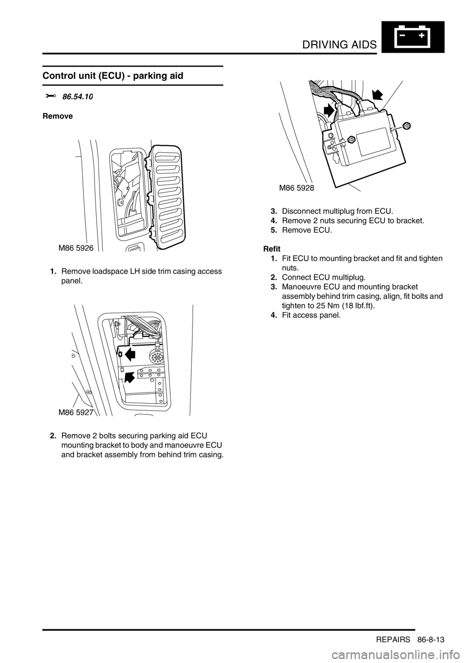
1.Remove loadspace LH side trim casing access
panel.
2.Remove 2 bolts securing parking aid ECU
mounting bracket to body and manoeuvre ECU
and bracket assembly from behind trim casing.3.Disconnect multiplug from ECU.
4.Remove 2 nuts securing ECU to bracket.
5.Remove ECU.
Refit
1.Fit ECU to mounting bracket and fit and tighten
nuts.
2.Connect ECU multiplug.
3.Manoeuvre ECU and mounting bracket
assembly behind trim casing, align, fit bolts and
tighten to 25 Nm (18 lbf.ft).
4.Fit access panel.
Page 1613 of 1672
DRIVING AIDS
86-8-14 REPAIRS
Sounder - parking aid rear
$% 86.54.19
Remove
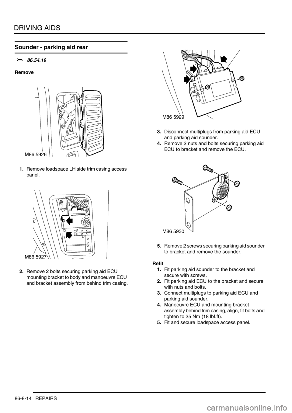
1.Remove loadspace LH side trim casing access
panel.
2.Remove 2 bolts securing parking aid ECU
mounting bracket to body and manoeuvre ECU
and bracket assembly from behind trim casing.3.Disconnect multiplugs from parking aid ECU
and parking aid sounder.
4.Remove 2 nuts and bolts securing parking aid
ECU to bracket and remove the ECU.
5.Remove 2 screws securing parking aid sounder
to bracket and remove the sounder.
Refit
1.Fit parking aid sounder to the bracket and
secure with screws.
2.Fit parking aid ECU to the bracket and secure
with nuts and bolts.
3.Connect multiplugs to parking aid ECU and
parking aid sounder.
4.Manoeuvre ECU and mounting bracket
assembly behind trim casing, align, fit bolts and
tighten to 25 Nm (18 lbf.ft).
5.Fit and secure loadspace access panel.
Page 1614 of 1672

DRIVING AIDS
REPAIRS 86-8-15
Sensor - parking aid - rear - inner
$% 86.54.23
Remove
1.Remove rear bumper assembly.
+ EXTERIOR FITTINGS, REPAIRS,
Bumper assembly - rear - from 03MY.
2.Remove 7 bolts and 5 screws securing closing
panel and remove panel.
3.Disconnect multiplug from sensor.
4.Release and remove sensor and sensor
housing.Refit
1.Clean sensor location on bumper.
2.Fit sensor housing to bumper, ensuring lug on
housing is aligned with cut-out in bumper.
3.Fit and secure sensor to housing.
4.Connect multiplug.
5.Fit closing panel and secure with bolts and
screws.
6.Fit bumper assembly.
+ EXTERIOR FITTINGS, REPAIRS,
Bumper assembly - rear - from 03MY.
Page 1615 of 1672

DRIVING AIDS
86-8-16 REPAIRS
Sensor - parking aid - rear - outer
$% 86.54.24
Remove
1.Remove tail lamp from bumper.
+ LIGHTING, REPAIRS, Lamp - tail/
flasher - bumper.
2.Disconnect multiplug from sensor.
3.Release and remove sensor and sensor
housing.
Refit
1.Clean sensor location on bumper.
2.Fit sensor housing to bumper, ensuring lug on
housing is aligned with cut-out in bumper.
3.Fit and secure sensor to housing.
4.Connect multiplug.
5.Fit tail lamp.
+ LIGHTING, REPAIRS, Lamp - tail/
flasher - bumper.
Page 1617 of 1672

NAVIGATION SYSTEM
87-2 DESCRIPTION AND OPERATION
Description
General
The navigation system provides audio and visual route guidance to help the driver reach a selected destination. The
system is an optional fit consisting of a Traffic Pro navigation computer and antenna, manufactured by Harman/
Becker Automotive Systems, which are fitted in place of the In Car Entertainment (ICE) head unit and antenna.
Compact Disc (CD) and radio functions are incorporated into the navigation computer.
The navigation system allows the driver to choose between the shortest and fastest routes between the vehicle's
current position and a selected destination, and to select a stopover point in the journey and a route that avoids
motorways, ferries and toll roads. Directions to Points Of Interest (POI) e.g. airports, hospitals, petrol stations etc,
either local, national or in another country, can also be selected. A traffic jam function enables the driver to request
diversion instructions, around an obstructed part of the selected route, during the journey. A Traffic Management
Control (TMC) function, currently only available in some European countries, monitors traffic broadcasts and
automatically selects an alternative route during the journey if the original route is effected by a traffic jam, accident
or road works etc.
The position of the vehicle is determined by the navigation computer using a combination of vehicle sensor inputs and
radio signals from the 24 Global Positioning System (GPS) satellites orbiting the earth. The position of the vehicle is
then plotted on a digitised map, loaded into the navigation computer from a CD-ROM, to determine the journey route
and provide the route guidance.
The GPS satellite signals are used for initial determination of the vehicle's position and periodic position updates. The
vehicle sensor inputs are used to monitor the vehicle's direction of travel and distance travelled between position
updates from the GPS satellite signals. The vehicle sensor inputs consist of:
lA vehicle speed signal from the ABS ECU, to monitor the distance travelled and for automatic volume control.
lA reverse gear signal from the selector and inhibitor switch of the automatic gearbox, or reverse gear switch of
the manual gearbox, to enable the navigation computer to differentiate between forward and rearward movement
of the vehicle.
lA gyro in the navigation computer, to monitor changes of direction, i.e. steering inputs.
The signal from each GPS satellite contains information about satellite position, almanac data and time (almanac data
is the current status of the satellite). Signals from between five and 11 of the GPS satellites can be received at a given
point on the earth's surface at any one time. The number and quality of separate GPS satellite signals received also
varies with vehicle location. In hilly or tree lined areas, built up areas with tall buildings, multi-storey car parks,
garages, tunnels, bridges and during heavy rain/thunderstorms, signal reception of some or all of the GPS satellites
will be poor or non existent.
A minimum of three separate GPS satellite signals are required for the navigation computer to calculate a three
dimensional (3D) positional fix. When only two signals are being received, the navigation computer will calculate a
less accurate two dimensional (2D) positional fix. The more widely dispersed that the GPS satellites are, the more
accurate the positional fix. The navigation computer can store information from a maximum of 12 GPS satellites at
any one time. When more than three signals are stored, the navigation computer selects the three most widely
dispersed signals for the position calculation.
GPS Antenna and diplexer unit
The GPS antenna is installed at the rear of the roof on the centreline. A diplexer unit on the underside of the GPS
antenna amplifies the radio signals received from the GPS satellites and transmits them through separate dedicated
co-axial cable to the navigation computer for processing.
Page 1618 of 1672
NAVIGATION SYSTEM
DESCRIPTION AND OPERATION 87-3
Navigation Computer
The navigation computer is installed in the DIN radio slot in the fascia. A spring loaded catch on each side of the
navigation computer secures it in position. Slide tools, installed in slots at the bottom front corners of the navigation
computer, are required to unlock the catches during removal.
The navigation computer contains all the hardware and software required for control of the navigation, radio and CD
systems, including the GPS receiver and a solid state piezo gyro for the navigation system. The piezo gyro measures
the motion of the vehicle around its vertical axis.
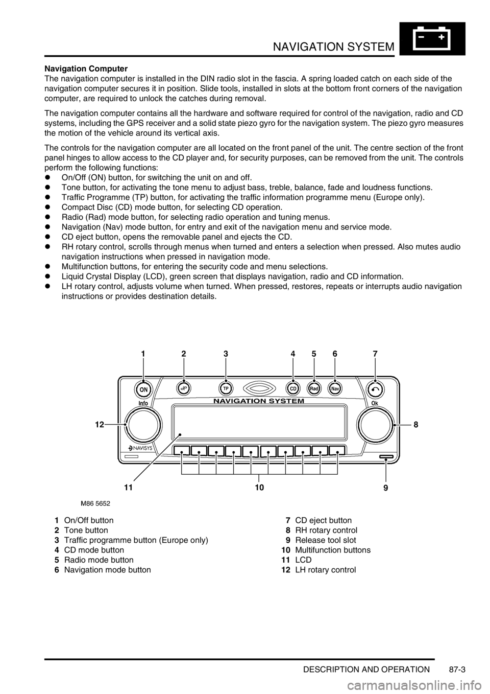
The controls for the navigation computer are all located on the front panel of the unit. The centre section of the front
panel hinges to allow access to the CD player and, for security purposes, can be removed from the unit. The controls
perform the following functions:
lOn/Off (ON) button, for switching the unit on and off.
lTone button, for activating the tone menu to adjust bass, treble, balance, fade and loudness functions.
lTraffic Programme (TP) button, for activating the traffic information programme menu (Europe only).
lCompact Disc (CD) mode button, for selecting CD operation.
lRadio (Rad) mode button, for selecting radio operation and tuning menus.
lNavigation (Nav) mode button, for entry and exit of the navigation menu and service mode.
lCD eject button, opens the removable panel and ejects the CD.
lRH rotary control, scrolls through menus when turned and enters a selection when pressed. Also mutes audio
navigation instructions when pressed in navigation mode.
lMultifunction buttons, for entering the security code and menu selections.
lLiquid Crystal Display (LCD), green screen that displays navigation, radio and CD information.
lLH rotary control, adjusts volume when turned. When pressed, restores, repeats or interrupts audio navigation
instructions or provides destination details.
1On/Off button
2Tone button
3Traffic programme button (Europe only)
4CD mode button
5Radio mode button
6Navigation mode button7CD eject button
8RH rotary control
9Release tool slot
10Multifunction buttons
11LCD
12LH rotary control
Page 1619 of 1672
NAVIGATION SYSTEM
87-4 DESCRIPTION AND OPERATION
Inputs and Outputs
In addition to the vehicle sensor and the antenna inputs, the navigation computer also receives the following:
lA permanent battery feed from the passenger compartment fusebox, to power the navigation function.
lAn ignition switched battery feed from the passenger compartment fusebox, to power the navigation, radio and
CD functions when the ignition switch is in positions I and II.
lAn illumination power feed for switch illumination and LCD backlighting when the exterior lights are on.
Navigation computer outputs consist of those for the ICE system speakers and to the auxiliary CD autochanger, where
fitted.
Security Code
The navigation computer is programmed with a five digit security code selected from numbers 1 to 7. If the battery or
the navigation computer are disconnected, the code is requested on the LCD the first time the navigation computer
is switched on after reconnection; this also occurs if a different removable panel is fitted.
The code is entered using the appropriate multifunction buttons. The navigation computer automatically starts to
operate when the fifth digit of the correct code is entered. If an incorrect code is entered, CODE is displayed on the
LCD to prompt another entry attempt. If an incorrect code is entered three times in succession, WAIT is displayed on
the LCD and the unit is disabled for approximately 60 minutes. If the navigation computer is switched off, the
remaining disabled time will resume when the power is restored.
Automatic Volume Control (AVC)
The AVC feature automatically increases and decreases the audio volume with increases and decreases of vehicle
road speed. The AVC feature, also known as the GAL setting, uses the vehicle speed signal from the ABS ECU and
can be turned off or adjusted to start at a different vehicle speed. The GAL setting is accessed through the User Menu
and can be set to between 0 and +15, where 0 is off and +1 to +15 progressively increase the vehicle speed at which
AVC starts to operate.
Page 1622 of 1672
NAVIGATION SYSTEM
DESCRIPTION AND OPERATION 87-7
Sensor Check
1Call up the SENSORS screen on the LCD:
lIf the navigation CD-ROM has not been installed before, press and hold multifunction button 1 then press
multifunction button 10.
lIf the navigation CD-ROM has been installed before, use the garage menu as detailed above.
2Drive the vehicle forwards a short distance at a speed greater than 2.5 mph (4 km/h) and ensure the road speed
counter on the SENSORS screen starts to increment.
3Select reverse gear and ensure the direction arrows on the SENSORS screen point rearwards.
4Ensure the GPS data on the SENSORS screen is displayed and updated.
NOTE: The GPS data will randomly display a GPS MODULE FAILURE message. This is not a fault condition, and
no action need be taken, provided the GPS data switches between the GPS MODULE FAILURE message and
actual GPS data.
5Exit the SENSORS screen:
lIf the navigation CD-ROM has not been installed before, press and hold multifunction button 1 then press
multifunction button 10.
lIf the navigation CD-ROM has been installed before, press the Nav button.
Calibration Routine
1Park the vehicle outside in an area clear of high buildings, trees etc.
NOTE: The more open the surrounding area is, the faster the system will acquire sufficient GPS satellite signals to
begin calibration. To minimise the calibration time, the vehicle should not be moved again until the calibration
ride.
2Turn the ignition switch to position II. If the navigation computer does not come on, press the navigation
computer ON button.
3If necessary, use the navigation computer multifunction buttons to enter the security code.
4Turn the ignition switch to position 0 and remove the ignition key.
5Press the navigation computer ON button.
6Call up the SENSORS screen on the LCD:
lIf the navigation CD-ROM has not been installed before, press and hold multifunction button 1 then press
multifunction button 10.
lIf the navigation CD-ROM has been installed before, use the garage menu as detailed above.
7Turn the LH rotary control to minimum volume.
8Wait for 30 minutes. If necessary, the vehicle can be left unattended and locked.
NOTE: Land Rover recommend a minimum of 30 minutes be allowed to elapse in order to ensure that only a short
distance need be driven to achieve calibration.
9After the 30 minutes have elapsed, ensure the navigation computer LCD shows a GPS almanac figure of 27 or
higher.
10Start the vehicle engine and allow to idle.
11Install the navigation CD-ROM.
12Wait until the navigation computer LCD prompts for a language to be selected. Turn the RH rotary control to
scroll through the options, highlight the required language and press the RH rotary control to select.
13The navigation computer LCD will prompt for a voice to be selected. Turn the RH rotary control to scroll through
the options, highlight the required voice and press the RH rotary control to select.
14Wait until the navigation computer LCD advises "language has been loaded OK". Press the RH rotary control to
confirm the language and voice selections.
15The navigation computer LCD will default to the CALIBRATION RIDE screen and should show the
CALIBRATION RIDE CAN START message. The GPS data and the road speed counter will also be shown.
16Drive the vehicle over a road route approximating that shown below (it is not necessary to copy the route
exactly). Calibration is complete when the navigation computer LCD switches to show DESTINATION & POI
and the satellite graphic. If all the pre calibration ride conditions were complied with, calibration is typically
achieved within 3 miles (5 km) and usually occurs when the vehicle returns to the start point. However,
calibration may be achieved earlier in the journey and, if it is, there is no need to complete the remainder of the
calibration route.