ESP inoperative LAND ROVER DISCOVERY 2002 Workshop Manual
[x] Cancel search | Manufacturer: LAND ROVER, Model Year: 2002, Model line: DISCOVERY, Model: LAND ROVER DISCOVERY 2002Pages: 1672, PDF Size: 46.1 MB
Page 403 of 1672

ENGINE MANAGEMENT SYSTEM - TD5
18-1-10 DESCRIPTION AND OPERATION
Mass Air Flow (MAF) sensor
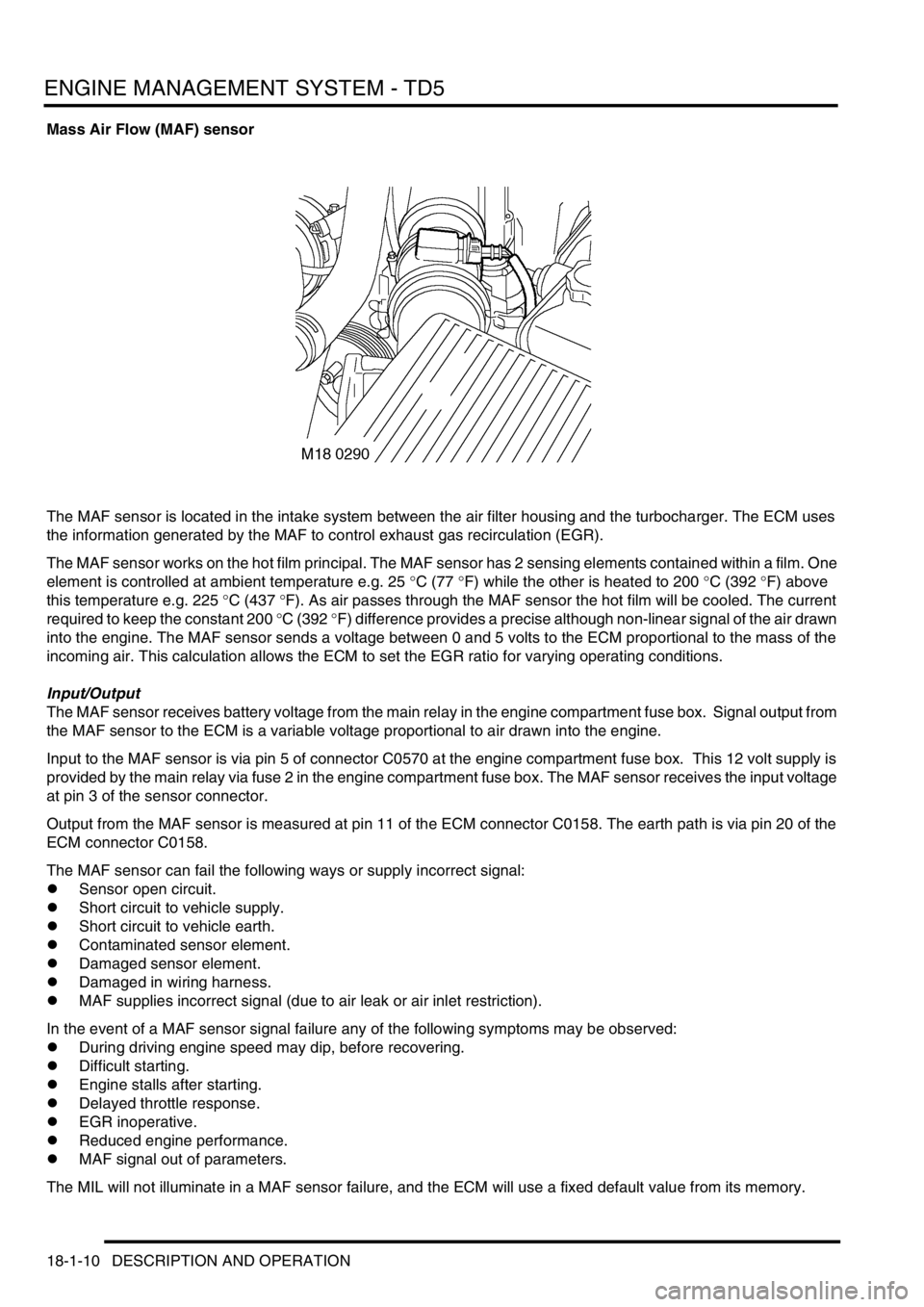
The MAF sensor is located in the intake system between the air filter housing and the turbocharger. The ECM uses
the information generated by the MAF to control exhaust gas recirculation (EGR).
The MAF sensor works on the hot film principal. The MAF sensor has 2 sensing elements contained within a film. One
element is controlled at ambient temperature e.g. 25
°C (77 °F) while the other is heated to 200 °C (392 °F) above
this temperature e.g. 225
°C (437 °F). As air passes through the MAF sensor the hot film will be cooled. The current
required to keep the constant 200
°C (392 °F) difference provides a precise although non-linear signal of the air drawn
into the engine. The MAF sensor sends a voltage between 0 and 5 volts to the ECM proportional to the mass of the
incoming air. This calculation allows the ECM to set the EGR ratio for varying operating conditions.
Input/Output
The MAF sensor receives battery voltage from the main relay in the engine compartment fuse box. Signal output from
the MAF sensor to the ECM is a variable voltage proportional to air drawn into the engine.
Input to the MAF sensor is via pin 5 of connector C0570 at the engine compartment fuse box. This 12 volt supply is
provided by the main relay via fuse 2 in the engine compartment fuse box. The MAF sensor receives the input voltage
at pin 3 of the sensor connector.
Output from the MAF sensor is measured at pin 11 of the ECM connector C0158. The earth path is via pin 20 of the
ECM connector C0158.
The MAF sensor can fail the following ways or supply incorrect signal:
lSensor open circuit.
lShort circuit to vehicle supply.
lShort circuit to vehicle earth.
lContaminated sensor element.
lDamaged sensor element.
lDamaged in wiring harness.
lMAF supplies incorrect signal (due to air leak or air inlet restriction).
In the event of a MAF sensor signal failure any of the following symptoms may be observed:
lDuring driving engine speed may dip, before recovering.
lDifficult starting.
lEngine stalls after starting.
lDelayed throttle response.
lEGR inoperative.
lReduced engine performance.
lMAF signal out of parameters.
The MIL will not illuminate in a MAF sensor failure, and the ECM will use a fixed default value from its memory.
Page 479 of 1672

ENGINE MANAGEMENT SYSTEM - V8
18-2-22 DESCRIPTION AND OPERATION
In the event of a MAF sensor signal failure any of the following symptoms may be observed:
lDuring driving engine rev/min may dip, before recovering.
lDifficult starting.
lEngine stalls after starting.
lDelayed throttle response.
lEmissions control inoperative.
lIdle speed control inoperative.
lReduced engine performance.
lMAF sensor signal offset.
There are two types of MAF sensor diagnostic check:
lThe MAF sensor signal is less than the minimum threshold for specific speed range – the engine must have
exceeded 200 rev/min for longer than 300 ms and remain above 400 rev/min. The signal must be less than the
threshold mapped against engine speed for longer than 500 ms.
lThe MAF sensor signal is greater than the maximum threshold for specific speed range – the engine must have
exceeded 200 rev/min for longer than 10 ms. The signal must be greater than the threshold mapped against
engine speed for longer than 300 ms.
If the MAF sensor fails the following fault codes will be produced and can be retrieved by TestBook:
Intake air temperature (IAT) sensor
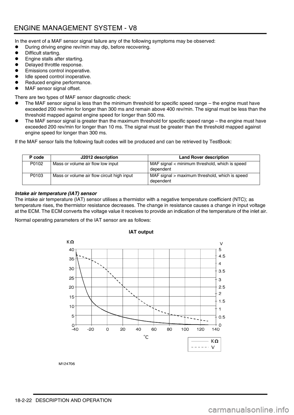
The intake air temperature (IAT) sensor utilises a thermistor with a negative temperature coefficient (NTC); as
temperature rises, the thermistor resistance decreases. The change in resistance causes a change in input voltage
at the ECM. The ECM converts the voltage value it receives to provide an indication of the temperature of the inlet air.
Normal operating parameters of the IAT sensor are as follows:
IAT output
P code J2012 description Land Rover description
P0102 Mass or volume air flow low input MAF signal < minimum threshold, which is speed
dependent
P0103 Mass or volume air flow circuit high input MAF signal > maximum threshold, which is speed
dependent
Page 483 of 1672

ENGINE MANAGEMENT SYSTEM - V8
18-2-26 DESCRIPTION AND OPERATION
In the event of a TP sensor signal failure any of the following symptoms may be observed:
lEngine performance concern.
lDelayed throttle response.
lFailure of emission control.
lClosed loop idle speed control inoperative.
lAutomatic gearbox kickdown inoperative.
lIncorrect altitude adaptation.
lMIL illuminated (NAS only).
There are three throttle position sensor diagnostic checks:
lTP sensor signal is greater than the maximum threshold value – the engine speed must be greater than 400 rev/
min for longer than 2 seconds and the signal must be greater than 96% for longer than 50 ms.
lTP sensor signal is less than the minimum threshold – the engine speed must be greater than 400 rev/min for
longer than 2 seconds and the signal must be less than 4% for longer than 50 ms.
lRatio of throttle position to mass of air flow – the calculated throttle angle must be outside limits when the engine
speed is between 800 rev/min and 4000 rev/min, the engine load is between 2 and 6.5 and the coolant
temperature is above -10
°C (14°F).
Should a malfunction of the TP sensor occur the following fault codes may be evident and can be retrieved by
TestBook.
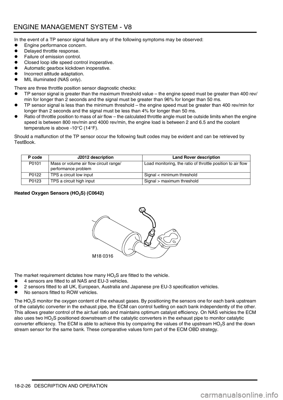
Heated Oxygen Sensors (HO
2S) (C0642)
The market requirement dictates how many HO
2S are fitted to the vehicle.
l4 sensors are fitted to all NAS and EU-3 vehicles.
l2 sensors fitted to all UK, European, Australia and Japanese pre EU-3 specification vehicles.
lNo sensors fitted to ROW vehicles.
The HO
2S monitor the oxygen content of the exhaust gases. By positioning the sensors one for each bank upstream
of the catalytic converter in the exhaust pipe, the ECM can control fuelling on each bank independently of the other.
This allows greater control of the air:fuel ratio and maintains optimum catalyst efficiency. On NAS vehicles the ECM
also uses two HO
2S positioned downstream of the catalytic converters in the exhaust pipe to monitor catalytic
converter efficiency. The ECM is able to achieve this by comparing the values of the upstream HO
2S and the down
stream sensor for the same bank. These comparative values form part of the ECM OBD strategy.
P code J2012 description Land Rover description
P0101 Mass or volume air flow circuit range/
performance problemLoad monitoring, the ratio of throttle position to air flow
P0122 TPS a circuit low input Signal < minimum threshold
P0123 TPS a circuit high input Signal > maximum threshold
Page 965 of 1672

FRONT SUSPENSION
60-26 DESCRIPTION AND OPERATION
Vehicle moving and turning left
When the vehicle is turning left, the accelerometers detect the cornering forces applied and transmit signals to the
ECU. The ECU determines that an opposing force must be applied to the torsion bars to counter the cornering forces.
The ECU supplies a current to the solenoid of the DCV2. Simultaneously, a current is sent from the ECU to the
pressure control valve which operates to restrict the flow of fluid returning to the reservoir.
The restriction causes the hydraulic pressure in the system to rise and the pressure is sensed by the pressure
transducer which sends a signal to the ECU. The ECU determines from the inputs it receives what pressure is required
and adjusts the pressure control valve accordingly.
The pressure in the system is applied to the annulus of each actuator, applying an opposing force to the torsion bar
and minimising the cornering effect on the vehicle and maintaining the vehicle attitude. The fluid displaced from the
full area of the actuator is returned to the reservoir via the valve block.
As the cornering force is removed when the vehicle straightens up, the ECU opens the pressure control valve to
reduce the pressure in the system. The fluid bleeds from the actuator back into the system as the cornering force is
reduced, removing the force from the torsion bar. When the vehicle is moving in a straight line DCV 2 closes.
Vehicle moving and turning right
When the vehicle is turning right, the accelerometers detect the cornering forces applied and transmit signals to the
ECU. The ECU determines that an opposing force must be applied to the torsion bars to counter the cornering forces.
The ECU supplies a current to the solenoid of the DCV1. Simultaneously, a current is sent from the ECU to the
pressure control valve which operates to restrict the flow of fluid through the by-pass gallery.
The restriction causes the hydraulic pressure in the system to rise and the pressure is sensed by the pressure
transducer which sends a signal corresponding to the pressure to the ECU. The ECU determines from the inputs it
receives what pressure is required and adjusts the pressure control valve accordingly.
The pressure in the system is applied to the full area of each actuator, applying an opposing force to the torsion bar
and minimising the cornering effect on the vehicle and maintaining the vehicle attitude. The fluid displaced from the
annulus of the actuator is returned to the reservoir via the valve block.
As the cornering force is removed when the vehicle straightens up, the ECU opens the pressure control valve to
reduce the pressure in the system. The fluid bleeds from the actuator back into the system as the cornering force is
reduced, removing the force from the torsion bar. When the vehicle is moving in a straight line the DCV 1 closes.
Vehicle moving in a straight line
The ECU is constantly monitoring the signals received from the accelerometers and operates the DCV's and pressure
control valve to maintain the vehicle attitude when the vehicle is moving.
Off-road driving
Off-road detection is achieved by the ECU by monitoring the signals from the upper and lower accelerometers for
varying degrees of body movement. Off-road driving generates differing signals to the accelerometers which in turn
produce differing outputs due to their vertical separation and the location of the roll centre of the vehicle. The two
signals are passed through a filter to remove any offset caused by the vehicle leaning or the terrain. The ECU then
uses this signal to calculate the percentage of road roughness.
Below 25 mph (40 km/h) the percentage of road roughness calculated is used by the ECU to limit the operation of the
ACE system. The system is completely inoperative at speeds below 2 mph (3 km/h). At speeds above 25 mph (40
km/h) the system disables the percentage road roughness signal and full ACE system assistance is restored.
Side slope detection
The ECU uses side slope detection when the upper and lower accelerometers detect an average acceleration of more
than
± 0.2 g and a road speed of less than 25 mph (40 km/h).
When side slope is detected both DCV's close to provide a 'locked bars' condition. This condition increases stability
and gives a consistent vehicle response. As the road speed increases up to 25 mph (40 km/h), the level of average
lateral acceleration must also increase and be maintained for the system to recognise that the vehicle is on a side
slope. If the side slope angle is steep and the road speed is low, the ECU will detect the side slope in a short time.