ird LAND ROVER FREELANDER 2001 User Guide
[x] Cancel search | Manufacturer: LAND ROVER, Model Year: 2001, Model line: FREELANDER, Model: LAND ROVER FREELANDER 2001Pages: 1007, PDF Size: 23.47 MB
Page 120 of 1007

TORQUE WRENCH SETTINGS
06-17
Manifolds and Exhaust Systems – KV6
TORQUE DESCRIPTION METRIC IMPERIAL
Coolant/breather hose bracket to inlet manifold bolt 9 Nm 6.5 lbf.ft
Exhaust heatshield to exhaust mounting bracket bolts 45 Nm 33 lbf.ft
Exhaust heatshield to IRD housing nut 45 Nm 33 lbf.ft
Exhaust heatshield to lower engine steady mounting bracket bolts 9 Nm 6.5 lbf.ft
Exhaust heatshield to pinion housing nuts 25 Nm 18 lbf.ft
Exhaust flange (LH) to front pipe nuts 50 Nm 37 lbf.ft
Exhaust flange (LH) to front pipe nuts 50 Nm 37 lbf.ft
Exhaust manifold to cylinder head nuts 45 Nm 33 lbf.ft
Exhaust front pipe to manifold flange nuts 50 Nm 37 lbf.ft
Heated Oxygen (HO
2S) sensor 55 Nm 41 lbf.ft
Inlet manifold chamber to inlet manifold bolts 18 Nm 13 lbf.ft
Inlet manifold chamber support brackets to RH camshaft cover bolts 10 Nm 7.5 lbf.ft
Inlet manifold to cylinder head nuts and bolts 25 Nm 18 lbf.ft
Intermediate pipe to front pipe nuts 50 Nm 37 lbf.ft
Intermediate pipe to front pipe nuts 50 Nm 44 lbf.ft
Lower engine steady to subframe bolt 100 Nm 74 lbf.ft
Lower engine steady to sump mounting bolt 100 Nm 74 lbf.ft
RH upper engine steady to body bolt 100 Nm 74 lbf.ft
RH upper engine steady to top arm bolt 100 Nm 74 lbf.ft
Tail pipe clamp nuts 55 Nm 41 lbf.ft
Page 124 of 1007

TORQUE WRENCH SETTINGS
06-21
Intermediate Reduction Drive
+ Apply sealant, Part No. STC 4600 to threads
TORQUE DESCRIPTION METRIC IMPERIAL
Drain plug35 Nm 26 lbf.ft
Exhaust heatshield to exhaust mounting bracket 45 Nm 33 lbf.ft
Exhaust heatshield to IRD screws (Td4) 30 Nm 22 lbf.ft
Exhaust heatshield to IRD nut (K1.8 and KV6) 45 Nm 33 lbf.ft
Filler / level plug35 Nm 26 lbf.ft
IRD unit to gearbox bolts 90 Nm 66 lbf.ft
IRD end cover bolts
+30 Nm 22 lbf.ft
IRD support bracket to cylinder block bolt (K1.8) 48 Nm 35 lbf.ft
IRD support bracket to cylinder block bolt (K1.8) 48 Nm 35 lbf.ft
IRD support bracket to IRD bolts (Td4)
⇒ M8
⇒ M1030 Nm
50 Nm22 lbf.ft
37 lbf.ft
IRD support bracket to IRD bolts (K1.8 and KV6) 50 Nm 37 lbf.ft
IRD support bracket to sump (K1.8 and KV6) 88 Nm 65 lbf.ft
Lower engine steady to IRD support bracket bolts 100 Nm 74 lbf.ft
Manifold heatshield to IRD support bracket bolts (K1.8 and KV6) 9 Nm 6.5 lbf.ft
Manifold heatshield to IRD support bracket bolts (K1.8 and KV6) 25 Nm 18 lbf.ft
Manifold heatshield to pinion housing nut (KV6) 45 Nm 33 lbf.ft
Manifold heatshield to IRD (Td4) 30 Nm 22 lbf.ft
Breather pipe bracket screw 9 Nm 7 lbf.ft
Mass damper to pinion housing nuts (K1.8) 25 Nm 18 lbf.ft
Pinion nut150 Nm 111 lbf.ft
Pinion housing nuts 25 Nm 18 lbf.ft
Propeller shaft to IRD flange bolts 40 Nm 30 lbf.ft
Page 125 of 1007

TORQUE WRENCH SETTINGS
06-22
Automatic Gearbox – Jatco
†Tighten in sequence.
+ Apply sealant, Part No. STC 4600 to threads
TORQUE DESCRIPTION METRIC IMPERIAL
Air blast cooler assembly to chassis bolts:
⇒ Lower10 Nm 7.5 lbf.ft
⇒ Upper5 Nm 3.5 lbf.ft
Air blast cooler fan cowl to matrix bolts 5 Nm 3.5 lbf.ft
Air blast cooler fan motor to cowl bolts 5 Nm 3.5 lbf.ft
Air blast cooler multiplug mounting bracket nut 10 Nm 7.5 lbf.ft
Air blast cooler pipe union nuts 25 Nm 18 lbf.ft
Crankshaft Position (CKP) Sensor 9 Nm 7 lbf.ft
Closing panel to gearbox panel bolt 10 Nm 7.5 lbf.ft
Drive plate to converter bolts 45 Nm 33 lbf.ft
Earth lead to gearbox housing bolt 25 Nm 18 lbf.ft
Fluid cooler to mounting bracket bolts (KV6) 25 Nm 18 lbf.ft
Fluid cooler mounting bracket bolts (KV6):
⇒ M825 Nm 18 lbf.ft
⇒ M1285 Nm 63 lbf.ft
Fluid cooler mounting bolts (Td4):
⇒ 2 off45 Nm 33 lbf.ft
⇒ 1 off25 Nm 18 lbf.ft
Fluid cooler hoses to gearbox 18 Nm 13 lbf.ft
Fluid cooler hose unions 18 Nm 13 lbf.ft
Fluid pan bolts
† +7 Nm 5 lbf.ft
Gearbox closing plate bolt (Td4) 10 Nm 7.5 lbf.ft
Gearbox drain plug 45 Nm 33 lbf.ft
Gearbox level plug 14 Nm 10 lbf.ft
Gearbox housing to sump 85 Nm 63 lbf.ft
Gearbox to engine bolts 85 Nm 63 lbf.ft
Gearbox mounting bracket bolts 85 Nm 63 lbf.ft
Gearbox mounting through bolt 100 Nm 74 lbf.ft
Inhibitor switch bolts 3 Nm 2.2 lbf.ft
IRD cooling hose retainer bolt (KV6) 25 Nm 18 lbf.ft
IRD support bracket mounting bolts
† (KV6) 50 Nm 37 lbf.ft
IRD support bracket to engine front mounting bracket bolts
† (KV6) 50 Nm 37 lbf.ft
IRD support bracket to sump bolts
† (KV6) 45 Nm 33 lbf.ft
IRD to gearbox bolts (KV6) 80 Nm 59 lbf.ft
Manifold heatshield to IRD support bracket (KV6):
⇒ Bolts9 Nm 7 lbf.ft
⇒ Nut45 Nm 33 lbf.ft
Manifold heatshield to IRD pinion housing nut (KV6) 25 Nm 18 lbf.ft
Selector housing nuts 10 Nm 7.5 lbf.ft
Selector cable trunnion nut 6 Nm 4.5 lbf.ft
Selector lever to gearbox selector shaft nut 25 Nm 18 lbf.ft
Starter motor to gearbox bolts 45 Nm 33 lbf.ft
Torque converter access plate bolts 9 Nm 7 lbf.ft
Page 126 of 1007

TORQUE WRENCH SETTINGS
06-23
Driveshafts
1 Tighten with weight of vehicle on suspension
TORQUE DESCRIPTION METRIC IMPERIAL
Adjustable transverse link to subframe nut and bolt
1120 Nm 89 lbf.ft
Adjustable transverse link to subframe nut and bolt
1120 Nm 89 lbf.ft
Fixed transverse link to subframe nut and bolt 120 Nm 89 lbf.ft
Front propeller shaft to IRD flange bolts and nuts 40 Nm 30 lbf.ft
Front propeller shaft to viscous coupling bolt 65 Nm 48 lbf.ft
Handbrake cable clip to subframe bolt 22 Nm 16 lbf.ft
Propeller shaft to IRD flange nuts and bolts 40 Nm 30 lbf.ft
Propeller shaft to rear axle nuts and bolt 65 Nm 48 lbf.ft
Propeller shaft to viscous coupling nuts and bolts 65 Nm 48 lbf.ft
Viscous coupling support bearing bolts 28 Nm 21 lbf.ft
Page 128 of 1007
TORQUE WRENCH SETTINGS
06-25
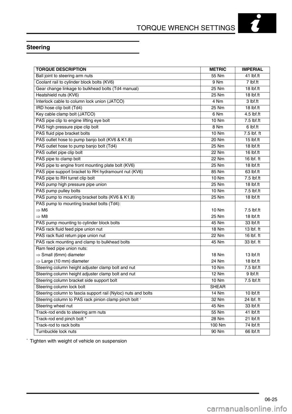
Steering
* Tighten with weight of vehicle on suspension
TORQUE DESCRIPTION METRIC IMPERIAL
Ball joint to steering arm nuts 55 Nm 41 lbf.ft
Coolant rail to cylinder block bolts (KV6) 9 Nm 7 lbf.ft
Gear change linkage to bulkhead bolts (Td4 manual) 25 Nm 18 lbf.ft
Heatshield nuts (KV6) 25 Nm 18 lbf.ft
Interlock cable to column lock union (JATCO) 4 Nm 3 lbf.ft
IRD hose clip bolt (Td4) 25 Nm 18 lbf.ft
Key cable clamp bolt (JATCO) 6 Nm 4.5 lbf.ft
PAS pipe clip to engine lifting eye bolt 10 Nm 7.5 lbf.ft
PAS high pressure pipe clip bolt 8 Nm 6 lbf.ft
PAS fluid pipe bracket bolts 10 Nm 7.5 lbf. ft
PAS outlet hose to pump banjo bolt (KV6 & K1.8) 20 Nm 15 lbf.ft
PAS outlet hose to pump banjo bolt (Td4) 25 Nm 18 lbf.ft
PAS outlet pipe clip bolt 22 Nm 16 lbf.ft
PAS pipe to clamp bolt 22 Nm 16 lbf. ft
PAS pipe to engine front mounting plate bolt (KV6) 25 Nm 18 lbf.ft
PAS pipe support bracket to RH hydramount nut (KV6) 85 Nm 63 lbf.ft
PAS pipe to RH turret clip bolt 10 Nm 7.5 lbf.ft
PAS pump high pressure pipe union 25 Nm 18 lbf.ft
PAS pump pulley bolts 10 Nm 7.5 lbf.ft
PAS pump to mounting bracket bolts (KV6 & K1.8) 25 Nm 18 lbf.ft
PAS pump to mounting bracket bolts (Td4):
⇒ M610 Nm 7.5 lbf.ft
⇒ M825 Nm 18 lbf.ft
PAS pump mounting to cylinder block bolts 45 Nm 33 lbf.ft
PAS rack fluid feed pipe union nut 18 Nm 13 lbf. ft
PAS rack fluid return pipe union nut 22 Nm 16 lbf. ft
PAS rack mounting and clamp to bulkhead bolts 45 Nm 33 lbf. ft
Ram feed pipe union nuts:
⇒ Small (6mm) diameter 18 Nm 13 lbf.ft
⇒ Large (10 mm) diameter 24 Nm 18 lbf.ft
Steering column height adjuster clamp bolt and nut 10 Nm 7.5 lbf.ft
Steering column height adjuster clamp bolt and nut 12 Nm 9 lbf.ft
Steering column bracket side support bolt 10 Nm 7.5 lbf.ft
Steering column lock bolt SHEAR
Steering column to fascia support rail (Nyloc) nuts and bolts 14 Nm 10 lbf.ft
Steering column to PAS rack pinion clamp pinch bolt
132 Nm 24 lbf. ft
Steering wheel nut 45 Nm 33 lbf.ft
Track-rod ends to steering arm nuts 55 Nm 41 lbf.ft
Track-rod end pinch bolt * 28 Nm 21 lbf.ft
Track-rod to rack bolts 100 Nm 74 lbf.ft
Turnbuckle lock nuts 90 Nm 66 lbf.ft
Page 140 of 1007
LIFTING AND TOWING
08-1
LIFTING AND TOWING
Jacking
The following instructions must be carried out before
raising the vehicle off the ground:
lUse a solid level surface.
lApply parking brake.
lSelect 1st. gear in main gearbox and ensure
HDC is not selected.
CAUTION: To avoid damage to under body
components of the vehicle, adhere to the
following jacking procedures:
DO NOT POSITION JACKS OR AXLE STANDS
UNDER THE FOLLOWING COMPONENTS:
lBumpers
lBrake or Fuel lines
lExhaust pipe
lSuspension components
lSteering rack and linkages
lFuel tank
lEngine sump
lGearbox
lIRD unit
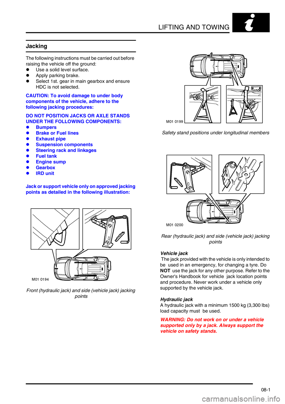
Jack or support vehicle only on approved jacking
points as detailed in the following illustration:
Front (hydraulic jack) and side (vehicle jack) jacking
pointsSafety stand positions under longitudinal members
Rear (hydraulic jack) and side (vehicle jack) jacking
points
Vehicle jack
The jack provided with the vehicle is only intended to
be used in an emergency, for changing a tyre. Do
NOT use the jack for any other purpose. Refer to the
Owner's Handbook for vehicle jack location points
and procedure. Never work under a vehicle only
supported by the vehicle jack.
Hydraulic jack
A hydraulic jack with a minimum 1500 kg (3,300 lbs)
load capacity must be used.
WARNING: Do not work on or under a vehicle
supported only by a jack. Always support the
vehicle on safety stands.
Page 147 of 1007

CAPACITIES, FLUIDS, LUBRICANTS AND SEALANTS
09-4
Sealants
The following table lists those sealants which are
used during repair / overhaul procedures covered in
this manual; it is essential that the sealant specified
for a particular procedure is used at all times.
Component Application Land Rover
Part No.
Td4 Engine Camshaft cover
gasket joint linesSTC 50550
Td4 Engine Sump gasket joint
linesSTC 50550
K 1.8 Engine Oil pressure switch
threadsSTC 50552
K 1.8 Engine Oil pressure relief
valve plug threadsSTC 50552
K 1.8 Engine Oil temperature
sensor threadsSTC 50552
K 1.8 Engine Oil pump cover
plate screwsSTC 50552
K 1.8 Engine Camshaft carrier to
cylinder headSTC 4600
K 1.8 Engine Bearing ladder to
cylinder blockSTC 4600
K 1.8 Engine Sump to bearing
ladderSTC 4600
K 1.8 Engine Oil rail to bearing
ladderSTC 4600
K 1.8 Engine Crankshaft rear oil
seal STC 50550
K 1.8 Engine Cylinder liners to
cylinder blockRTC 3347
KV6 Engine Camshaft timing
belt backplate
cover boltsSTC 50552
KV6 Engine Oil pressure relief
valve plug threadsSTC 50552
KV6 Engine Oil pump cover
plate screwsSTC 50552
KV6 Engine Camshaft carrier to
cylinder headSTC 4600
KV6 Engine Sump to lower
crankcaseSTC 4600
KV6 Engine Oil pick-up strainer
boltSTC 50552
KV6 Engine Lower crankcase to
cylinder blockSTC 50550
KV6 Engine Cylinder liners to
cylinder blockRTC 3347
KV6 Engine Coolant stub pipe to
cylinder blockSTC 50554
Engine
Management
System -
MEMSSensor - Engine
Coolant
temperature (ECT)STC 50552
Cooling
System - KV6Cylinder block drain
plugSTC 50552
Manual
Gearbox - PG12 top bolts -
gearbox to engineSTC 50552
Manual
Gearbox -
GetragRear cover to
gearcaseSTC 4600
Manual
Gearbox -
GetragGearshift cover STC 4600
Intermediate
Reduction
DriveEnd cover gasket -
IRD housingSTC 4600
Automatic
Gearbox -
JatcoFluid pan to
gearcaseSTC 4600
Rear Axle and
Final DriveDifferential cover to
casingSTC 3811
Page 164 of 1007
MAINTENANCE
MAINTENANCE 10-17
PAS Fluid Level
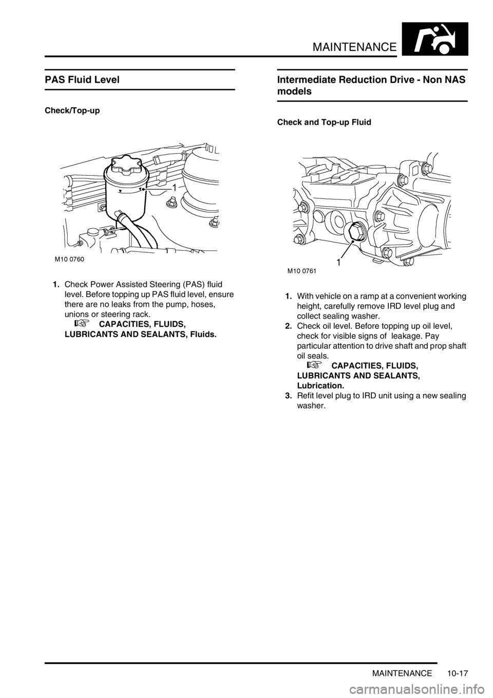
Check/Top-up
1.Check Power Assisted Steering (PAS) fluid
level. Before topping up PAS fluid level, ensure
there are no leaks from the pump, hoses,
unions or steering rack.
+ CAPACITIES, FLUIDS,
LUBRICANTS AND SEALANTS, Fluids.
Intermediate Reduction Drive - Non NAS
models
Check and Top-up Fluid
1.With vehicle on a ramp at a convenient working
height, carefully remove IRD level plug and
collect sealing washer.
2.Check oil level. Before topping up oil level,
check for visible signs of leakage. Pay
particular attention to drive shaft and prop shaft
oil seals.
+ CAPACITIES, FLUIDS,
LUBRICANTS AND SEALANTS,
Lubrication.
3.Refit level plug to IRD unit using a new sealing
washer.
Page 165 of 1007
MAINTENANCE
10-18 MAINTENANCE
Intermediate Reduction Drive - NAS
models
Check and Top-up Fluid
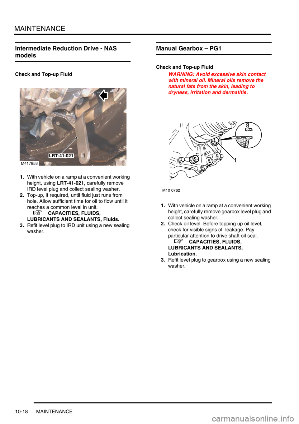
1.With vehicle on a ramp at a convenient working
height, using LRT-41-021, carefully remove
IRD level plug and collect sealing washer.
2.Top-up, if required, until fluid just runs from
hole. Allow sufficient time for oil to flow until it
reaches a common level in unit.
+ CAPACITIES, FLUIDS,
LUBRICANTS AND SEALANTS, Fluids.
3.Refit level plug to IRD unit using a new sealing
washer.
Manual Gearbox – PG1
Check and Top-up Fluid
WARNING: Avoid excessive skin contact
with mineral oil. Mineral oils remove the
natural fats from the skin, leading to
dryness, irritation and dermatitis.
1.With vehicle on a ramp at a convenient working
height, carefully remove gearbox level plug and
collect sealing washer.
2.Check oil level. Before topping up oil level,
check for visible signs of leakage. Pay
particular attention to drive shaft oil seal.
+ CAPACITIES, FLUIDS,
LUBRICANTS AND SEALANTS,
Lubrication.
3.Refit level plug to gearbox using a new sealing
washer.
M417853
LRT-41-021
Page 206 of 1007
ENGINE - K SERIES KV6
REPAIRS 12-3-29
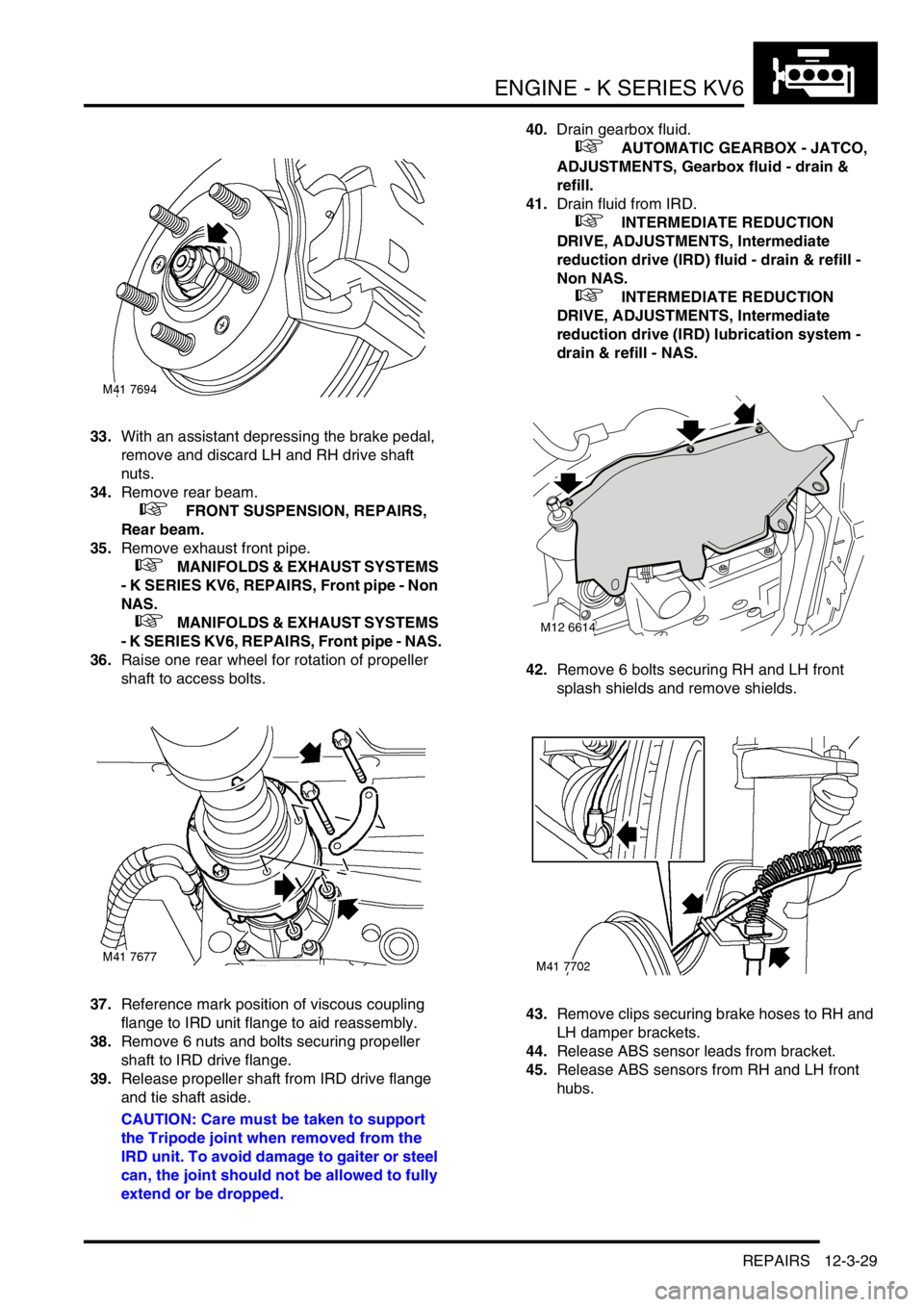
33.With an assistant depressing the brake pedal,
remove and discard LH and RH drive shaft
nuts.
34.Remove rear beam.
+ FRONT SUSPENSION, REPAIRS,
Rear beam.
35.Remove exhaust front pipe.
+ MANIFOLDS & EXHAUST SYSTEMS
- K SERIES KV6, REPAIRS, Front pipe - Non
NAS.
+ MANIFOLDS & EXHAUST SYSTEMS
- K SERIES KV6, REPAIRS, Front pipe - NAS.
36.Raise one rear wheel for rotation of propeller
shaft to access bolts.
37.Reference mark position of viscous coupling
flange to IRD unit flange to aid reassembly.
38.Remove 6 nuts and bolts securing propeller
shaft to IRD drive flange.
39.Release propeller shaft from IRD drive flange
and tie shaft aside.
CAUTION: Care must be taken to support
the Tripode joint when removed from the
IRD unit. To avoid damage to gaiter or steel
can, the joint should not be allowed to fully
extend or be dropped.40.Drain gearbox fluid.
+ AUTOMATIC GEARBOX - JATCO,
ADJUSTMENTS, Gearbox fluid - drain &
refill.
41.Drain fluid from IRD.
+ INTERMEDIATE REDUCTION
DRIVE, ADJUSTMENTS, Intermediate
reduction drive (IRD) fluid - drain & refill -
Non NAS.
+ INTERMEDIATE REDUCTION
DRIVE, ADJUSTMENTS, Intermediate
reduction drive (IRD) lubrication system -
drain & refill - NAS.
42.Remove 6 bolts securing RH and LH front
splash shields and remove shields.
43.Remove clips securing brake hoses to RH and
LH damper brackets.
44.Release ABS sensor leads from bracket.
45.Release ABS sensors from RH and LH front
hubs.
M12 6614