heater LAND ROVER FREELANDER 2001 Owner's Manual
[x] Cancel search | Manufacturer: LAND ROVER, Model Year: 2001, Model line: FREELANDER, Model: LAND ROVER FREELANDER 2001Pages: 1007, PDF Size: 23.47 MB
Page 619 of 1007
DOORS
76-1-14 REPAIRS
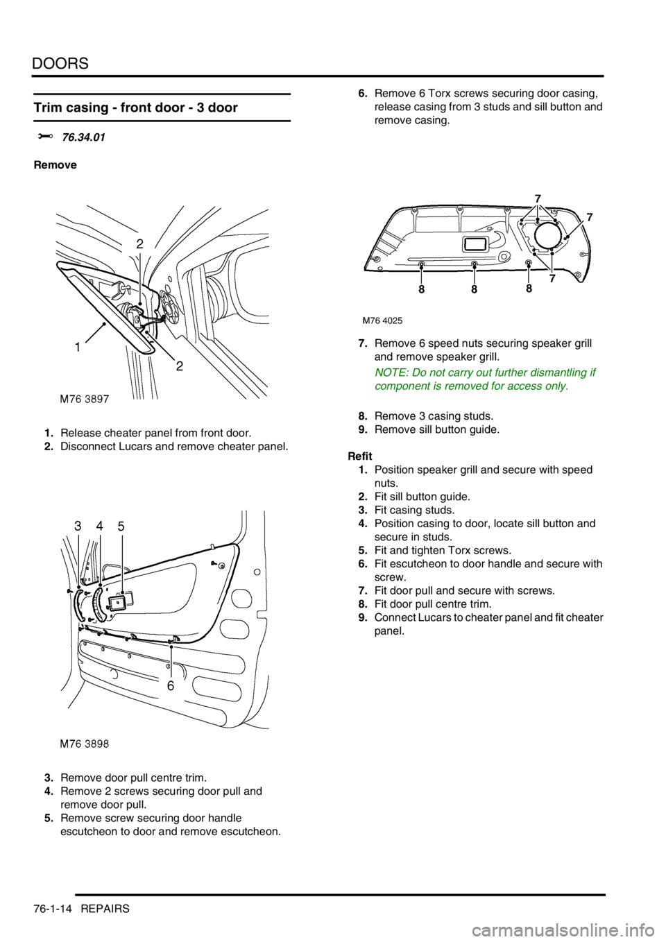
Trim casing - front door - 3 door
$% 76.34.01
Remove
1.Release cheater panel from front door.
2.Disconnect Lucars and remove cheater panel.
3.Remove door pull centre trim.
4.Remove 2 screws securing door pull and
remove door pull.
5.Remove screw securing door handle
escutcheon to door and remove escutcheon.6.Remove 6 Torx screws securing door casing,
release casing from 3 studs and sill button and
remove casing.
7.Remove 6 speed nuts securing speaker grill
and remove speaker grill.
NOTE: Do not carry out further dismantling if
component is removed for access only.
8.Remove 3 casing studs.
9.Remove sill button guide.
Refit
1.Position speaker grill and secure with speed
nuts.
2.Fit sill button guide.
3.Fit casing studs.
4.Position casing to door, locate sill button and
secure in studs.
5.Fit and tighten Torx screws.
6.Fit escutcheon to door handle and secure with
screw.
7.Fit door pull and secure with screws.
8.Fit door pull centre trim.
9.Connect Lucars to cheater panel and fit cheater
panel.
Page 620 of 1007
DOORS
REPAIRS 76-1-15
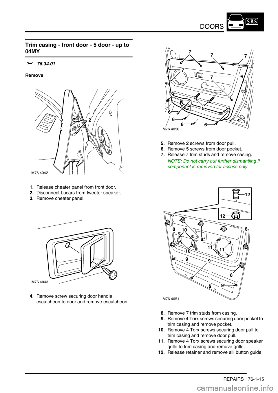
Trim casing - front door - 5 door - up to
04MY
$% 76.34.01
Remove
1.Release cheater panel from front door.
2.Disconnect Lucars from tweeter speaker.
3.Remove cheater panel.
4.Remove screw securing door handle
escutcheon to door and remove escutcheon.5.Remove 2 screws from door pull.
6.Remove 5 screws from door pocket.
7.Release 7 trim studs and remove casing.
NOTE: Do not carry out further dismantling if
component is removed for access only.
8.Remove 7 trim studs from casing.
9.Remove 4 Torx screws securing door pocket to
trim casing and remove pocket.
10.Remove 4 Torx screws securing door pull to
trim casing and remove door pull.
11.Remove 4 Torx screws securing door speaker
grille to trim casing and remove grille.
12.Release retainer and remove sill button guide.
Page 621 of 1007
DOORS
76-1-16 REPAIRS
Refit
1.Fit sill button guide to trim casing and secure
with retainer.
2.Fit speaker grille to trim casing and secure with
Torx screws.
3.Fit door pull to trim casing and secure with Torx
screws.
4.Fit door pocket to trim casing and secure with
Torx screws.
5.Fit trim studs to casing.
6.Fit trim casing to door and secure trim studs.
7.Fit screws to door pull and door pocket.
8.Fit door release escutcheon and secure with
screw.
9.Position cheater panel, connect Lucars to
tweeter speaker and fit cheater panel.
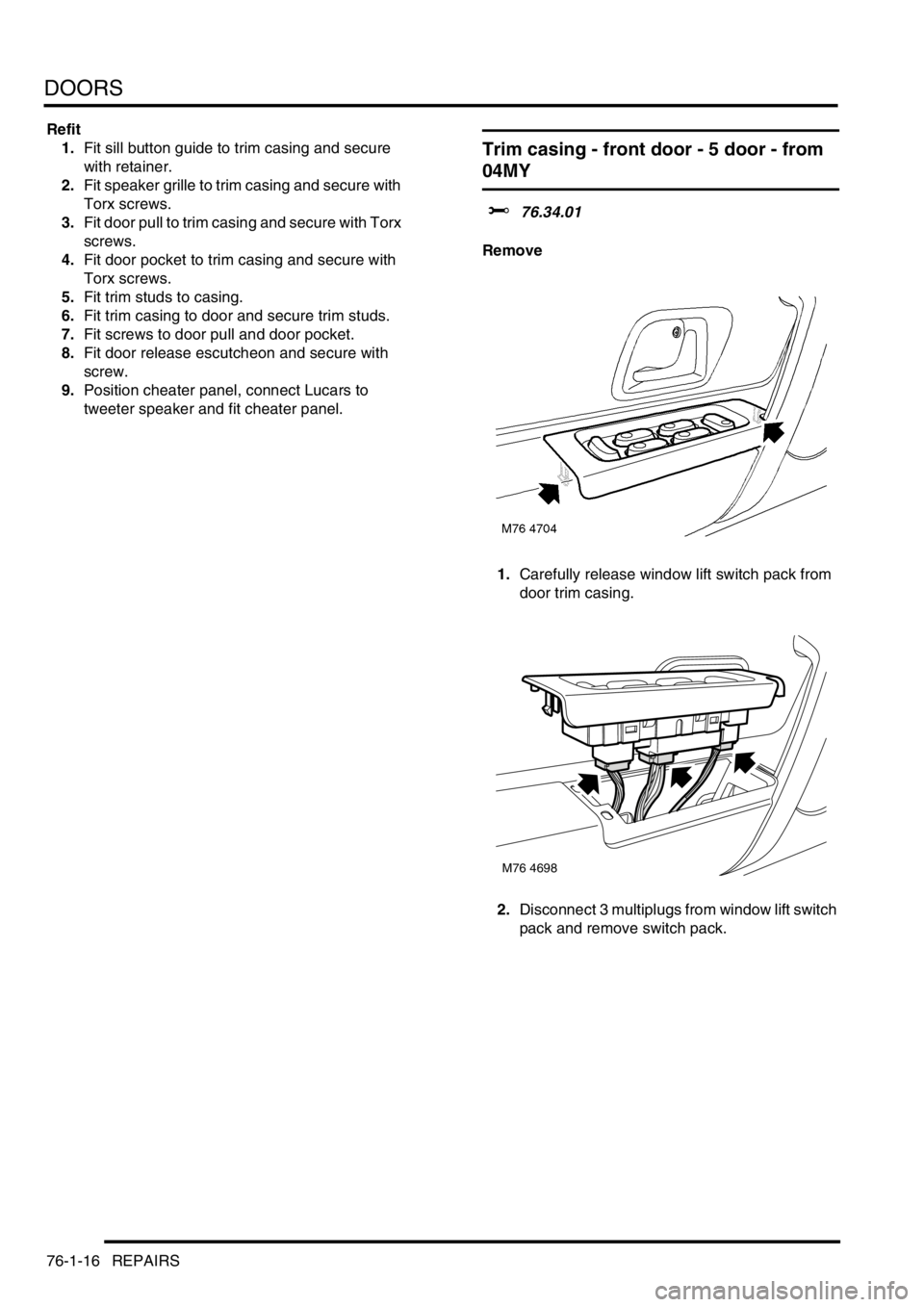
Trim casing - front door - 5 door - from
04MY
$% 76.34.01
Remove
1.Carefully release window lift switch pack from
door trim casing.
2.Disconnect 3 multiplugs from window lift switch
pack and remove switch pack.
M76 4698
Page 645 of 1007
EXTERIOR FITTINGS
76-2-4 REPAIRS
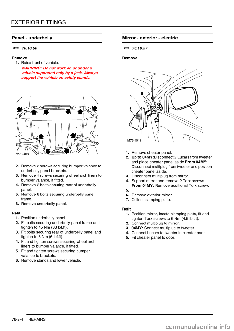
Panel - underbelly
$% 76.10.50
Remove
1.Raise front of vehicle.
WARNING: Do not work on or under a
vehicle supported only by a jack. Always
support the vehicle on safety stands.
2.Remove 2 screws securing bumper valance to
underbelly panel brackets.
3.Remove 4 screws securing wheel arch liners to
bumper valance, if fitted.
4.Remove 2 bolts securing rear of underbelly
panel.
5.Remove 6 bolts securing underbelly panel
frame.
6.Remove underbelly panel.
Refit
1.Position underbelly panel.
2.Fit bolts securing underbelly panel frame and
tighten to 45 Nm (33 lbf.ft).
3.Fit bolts securing rear of underbelly panel and
tighten to 8 Nm (6 lbf.ft).
4.Fit and tighten screws securing wheel arch
liners to bumper valance, if fitted.
5.Fit and tighten screws securing bumper
valance to brackets.
6.Remove stands and lower vehicle.
Mirror - exterior - electric
$% 76.10.57
Remove
1.Remove cheater panel.
2. Up to 04MY:Disconnect 2 Lucars from tweeter
and place cheater panel aside.From 04MY:
Disconnect multiplug from tweeter and position
cheater panel aside.
3.Disconnect multiplug from mirror.
4.Support mirror and remove 2 Torx screws.
From 04MY: Remove additional Torx screw.
5.
6.Remove exterior mirror.
7.Collect clamping plate.
Refit
1.Position mirror, locate clamping plate, fit and
tighten Torx screws to 6 Nm (4.5 lbf.ft).
2.Connect multiplug to mirror.
3. 04MY: Connect multiplug to tweeter.
4.Connect Lucars to tweeter in cheater panel.
5.Fit cheater panel to door.
Page 670 of 1007
INTERIOR TRIM COMPONENTS
REPAIRS 76-3-9
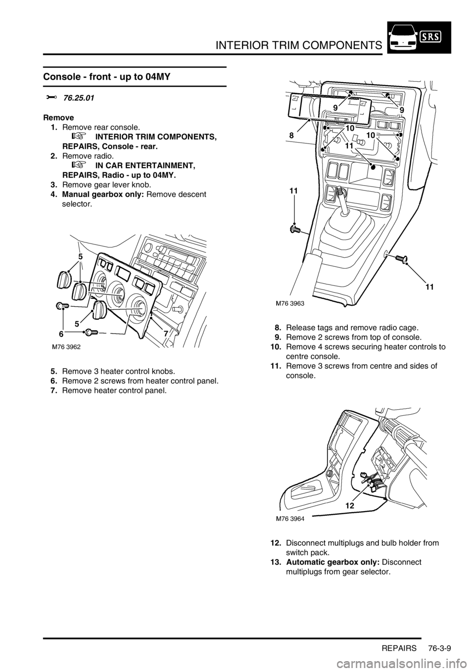
Console - front - up to 04MY
$% 76.25.01
Remove
1.Remove rear console.
+ INTERIOR TRIM COMPONENTS,
REPAIRS, Console - rear.
2.Remove radio.
+ IN CAR ENTERTAINMENT,
REPAIRS, Radio - up to 04MY.
3.Remove gear lever knob.
4. Manual gearbox only: Remove descent
selector.
5.Remove 3 heater control knobs.
6.Remove 2 screws from heater control panel.
7.Remove heater control panel.8.Release tags and remove radio cage.
9.Remove 2 screws from top of console.
10.Remove 4 screws securing heater controls to
centre console.
11.Remove 3 screws from centre and sides of
console.
12.Disconnect multiplugs and bulb holder from
switch pack.
13. Automatic gearbox only: Disconnect
multiplugs from gear selector.
Page 671 of 1007
INTERIOR TRIM COMPONENTS
76-3-10 REPAIRS
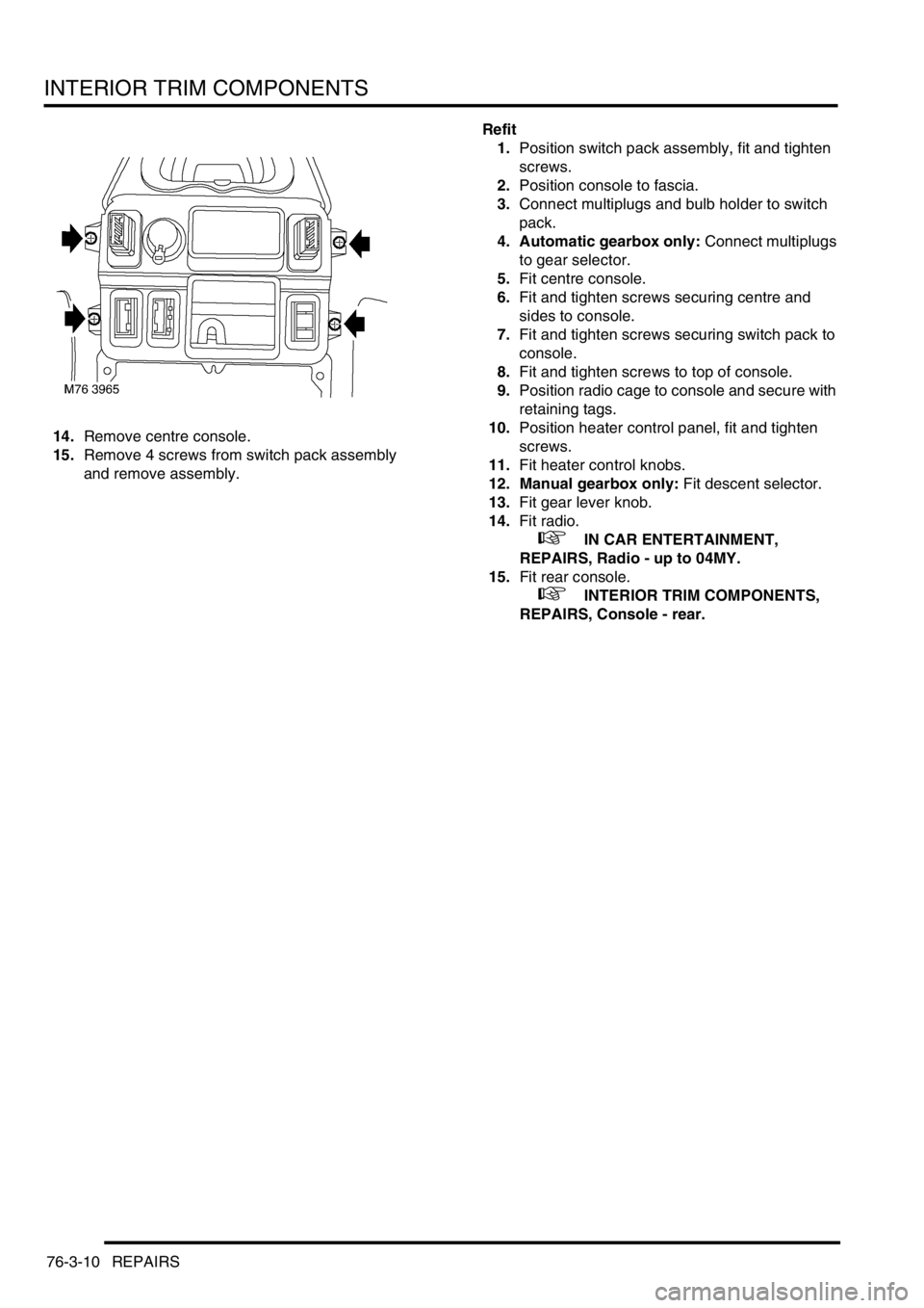
14.Remove centre console.
15.Remove 4 screws from switch pack assembly
and remove assembly.Refit
1.Position switch pack assembly, fit and tighten
screws.
2.Position console to fascia.
3.Connect multiplugs and bulb holder to switch
pack.
4. Automatic gearbox only: Connect multiplugs
to gear selector.
5.Fit centre console.
6.Fit and tighten screws securing centre and
sides to console.
7.Fit and tighten screws securing switch pack to
console.
8.Fit and tighten screws to top of console.
9.Position radio cage to console and secure with
retaining tags.
10.Position heater control panel, fit and tighten
screws.
11.Fit heater control knobs.
12. Manual gearbox only: Fit descent selector.
13.Fit gear lever knob.
14.Fit radio.
+ IN CAR ENTERTAINMENT,
REPAIRS, Radio - up to 04MY.
15.Fit rear console.
+ INTERIOR TRIM COMPONENTS,
REPAIRS, Console - rear.
Page 680 of 1007
INTERIOR TRIM COMPONENTS
REPAIRS 76-3-19
Fascia - from 04MY
$% 76.46.23
Remove
1.Remove instrument pack.
+ INSTRUMENTS, REPAIRS,
Instrument panel - from 04MY.
2.Remove the Radio/CD module.
+ IN CAR ENTERTAINMENT,
REPAIRS, Radio/CD - from 04MY.
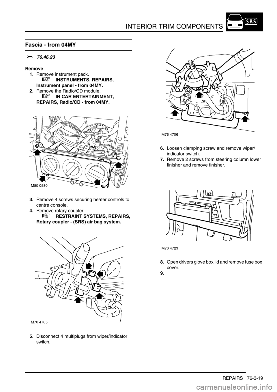
3.Remove 4 screws securing heater controls to
centre console.
4.Remove rotary coupler.
+ RESTRAINT SYSTEMS, REPAIRS,
Rotary coupler - (SRS) air bag system.
5.Disconnect 4 multiplugs from wiper/indicator
switch.6.Loosen clamping screw and remove wiper/
indicator switch.
7.Remove 2 screws from steering column lower
finisher and remove finisher.
8.Open drivers glove box lid and remove fuse box
cover.
9.
Page 683 of 1007
INTERIOR TRIM COMPONENTS
76-3-22 REPAIRS
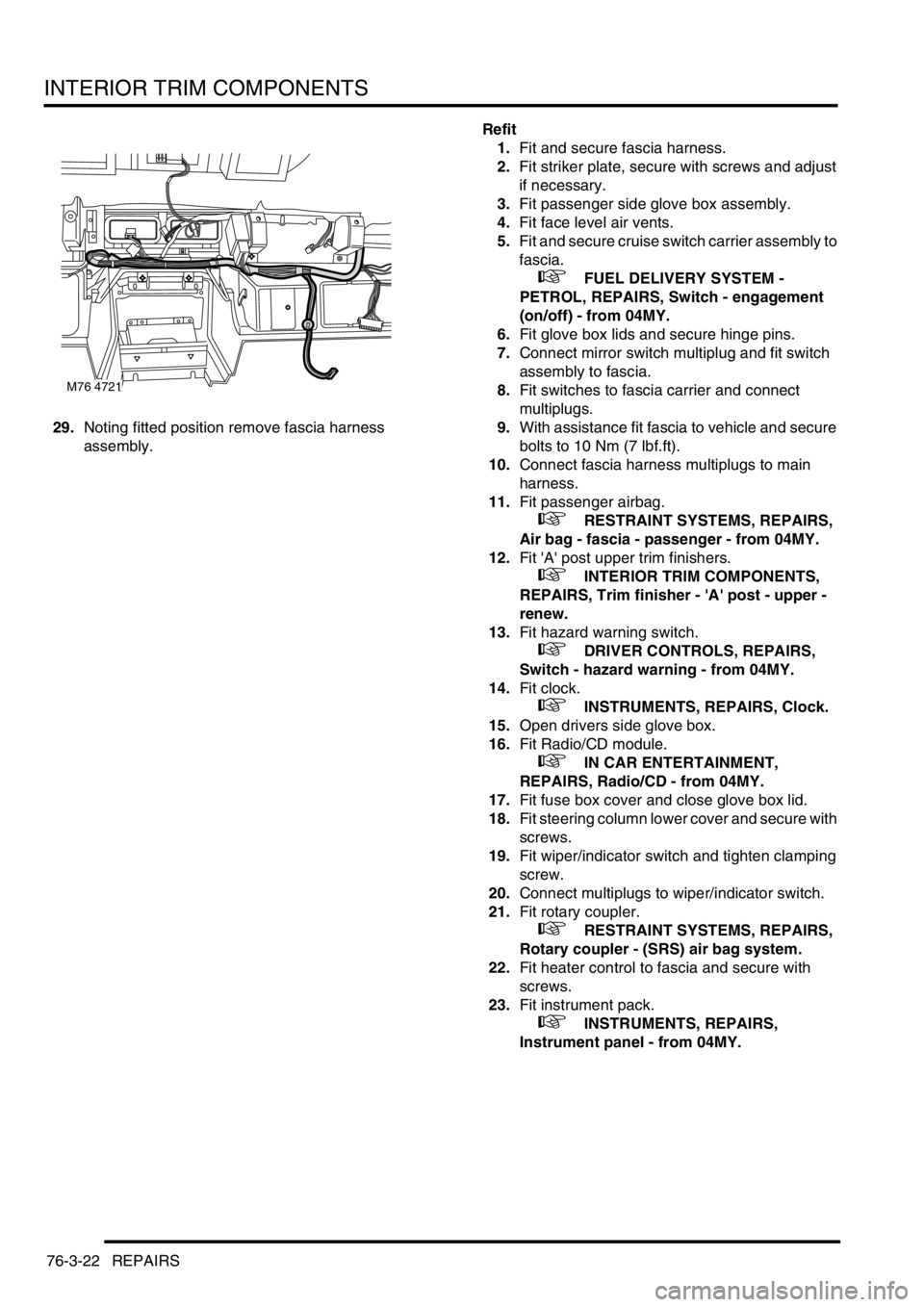
29.Noting fitted position remove fascia harness
assembly.Refit
1.Fit and secure fascia harness.
2.Fit striker plate, secure with screws and adjust
if necessary.
3.Fit passenger side glove box assembly.
4.Fit face level air vents.
5.Fit and secure cruise switch carrier assembly to
fascia.
+ FUEL DELIVERY SYSTEM -
PETROL, REPAIRS, Switch - engagement
(on/off) - from 04MY.
6.Fit glove box lids and secure hinge pins.
7.Connect mirror switch multiplug and fit switch
assembly to fascia.
8.Fit switches to fascia carrier and connect
multiplugs.
9.With assistance fit fascia to vehicle and secure
bolts to 10 Nm (7 lbf.ft).
10.Connect fascia harness multiplugs to main
harness.
11.Fit passenger airbag.
+ RESTRAINT SYSTEMS, REPAIRS,
Air bag - fascia - passenger - from 04MY.
12.Fit 'A' post upper trim finishers.
+ INTERIOR TRIM COMPONENTS,
REPAIRS, Trim finisher - 'A' post - upper -
renew.
13.Fit hazard warning switch.
+ DRIVER CONTROLS, REPAIRS,
Switch - hazard warning - from 04MY.
14.Fit clock.
+ INSTRUMENTS, REPAIRS, Clock.
15.Open drivers side glove box.
16.Fit Radio/CD module.
+ IN CAR ENTERTAINMENT,
REPAIRS, Radio/CD - from 04MY.
17.Fit fuse box cover and close glove box lid.
18.Fit steering column lower cover and secure with
screws.
19.Fit wiper/indicator switch and tighten clamping
screw.
20.Connect multiplugs to wiper/indicator switch.
21.Fit rotary coupler.
+ RESTRAINT SYSTEMS, REPAIRS,
Rotary coupler - (SRS) air bag system.
22.Fit heater control to fascia and secure with
screws.
23.Fit instrument pack.
+ INSTRUMENTS, REPAIRS,
Instrument panel - from 04MY.
M76 4721
Page 692 of 1007
SCREENS
REPAIRS 76-4-1
SCREENS REPAIRS
Windscreen
$% 76.81.01
The following equipment is required: Cutting wire
and handles, Windscreen repair kit, Sealer applicator
gun and Suction cups
Wear protective gloves when handling glass,
solvents and primers.
Wear suitable eye protection when removing and
refitting glass.
Remove
1.Remove air intake panel.
+ HEATING AND VENTILATION,
REPAIRS, Plenum - air intake.
2.Remove sun visors and sun visor retaining
clips.
3.Remove 'A' post upper trim casings.
+ INTERIOR TRIM COMPONENTS,
REPAIRS, Trim finisher - 'A' post - upper -
renew.
4.Remove retaining stud from front of headlining.
5.Remove interior mirror.
6.Fit protection to bonnet and areas around
screen.
7.Cover heater ducts with masking tape.
8.Cover interior of vehicle with protective sheet.
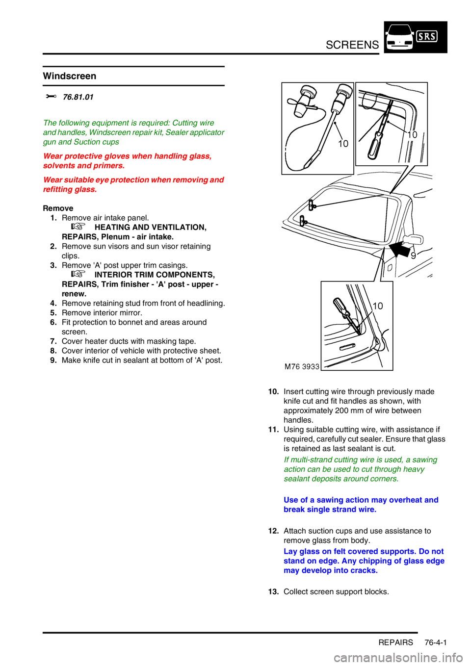
9.Make knife cut in sealant at bottom of 'A' post.
10.Insert cutting wire through previously made
knife cut and fit handles as shown, with
approximately 200 mm of wire between
handles.
11.Using suitable cutting wire, with assistance if
required, carefully cut sealer. Ensure that glass
is retained as last sealant is cut.
If multi-strand cutting wire is used, a sawing
action can be used to cut through heavy
sealant deposits around corners.
Use of a sawing action may overheat and
break single strand wire.
12.Attach suction cups and use assistance to
remove glass from body.
Lay glass on felt covered supports. Do not
stand on edge. Any chipping of glass edge
may develop into cracks.
13.Collect screen support blocks.
Page 770 of 1007
PANEL REPAIRS
WELDING PROCEDURES 77-2-15
WE LDING PROCEDURE S
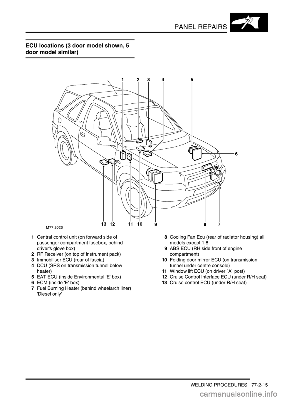
ECU locations (3 door model shown, 5
door model similar)
1Central control unit (on forward side of
passenger compartment fusebox, behind
driver's glove box)
2RF Receiver (on top of instrument pack)
3Immobiliser ECU (rear of fascia)
4DCU (SRS on transmission tunnel below
heater)
5EAT ECU (inside Environmental 'E' box)
6ECM (inside 'E' box)
7Fuel Burning Heater (behind wheelarch liner)
'Diesel only'8Cooling Fan Ecu (rear of radiator housing) all
models except 1.8
9ABS ECU (RH side front of engine
compartment)
10Folding door mirror ECU (on transmission
tunnel under centre console)
11Window lift ECU (on driver `A` post)
12Cruise Control Interface ECU (under R/H seat)
13Cruise control ECU (under R/H seat)