Oil pump LAND ROVER FREELANDER 2001 Owner's Guide
[x] Cancel search | Manufacturer: LAND ROVER, Model Year: 2001, Model line: FREELANDER, Model: LAND ROVER FREELANDER 2001Pages: 1007, PDF Size: 23.47 MB
Page 264 of 1007
ENGINE - K SERIES KV6
OVERHAUL 12-3-87
Refit
1.Fit oil pump gasket.
+ ENGINE - K SERIES KV6,
OVERHAUL, Oil pump - Overhaul.
2.Fit engine sump.
+ ENGINE - K SERIES KV6,
OVERHAUL, Sump - engine oil.
3.Fit crankshaft rear oil seal.
+ ENGINE - K SERIES KV6,
OVERHAUL, Crankshaft rear oil seal.
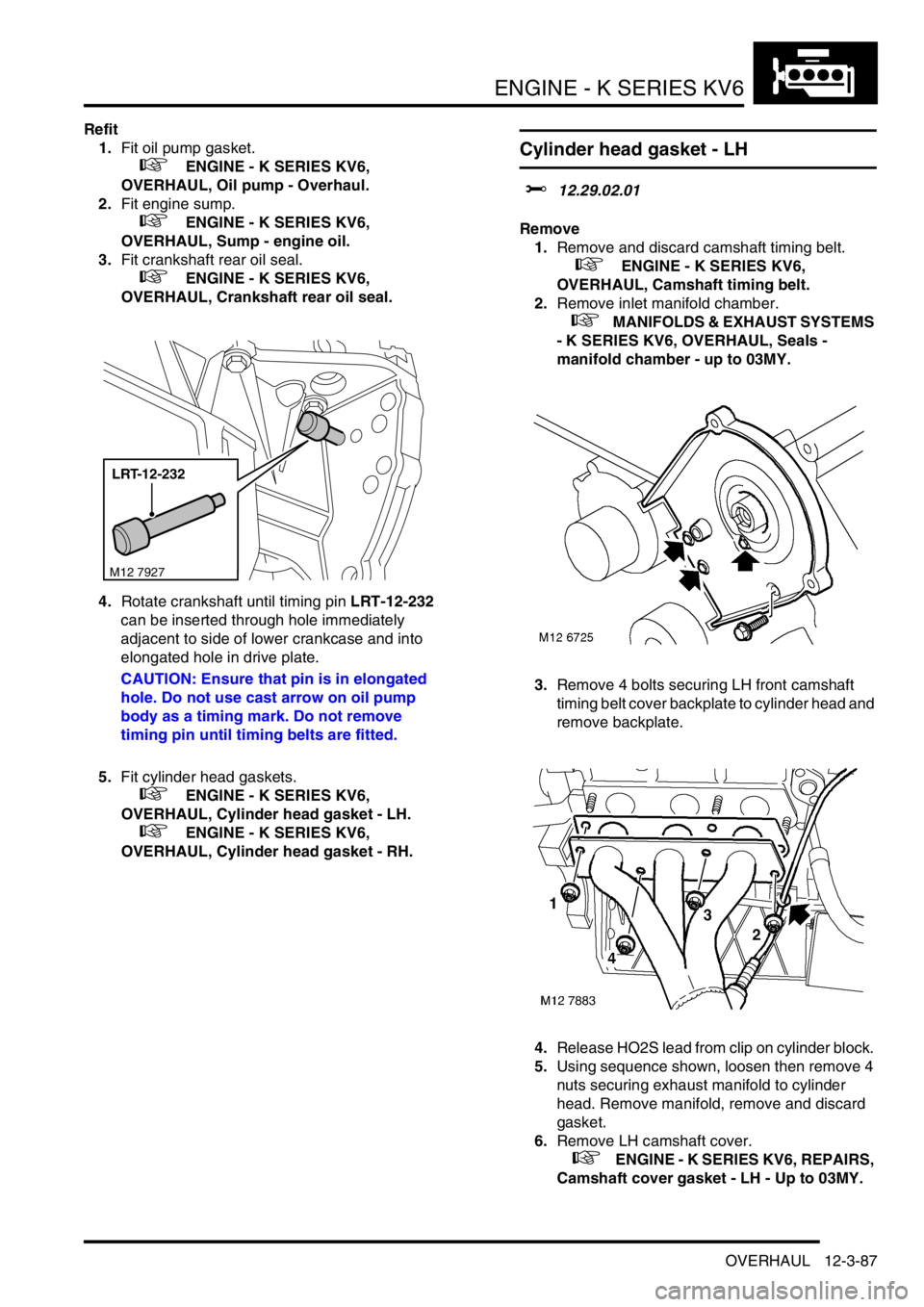
4.Rotate crankshaft until timing pin LRT-12-232
can be inserted through hole immediately
adjacent to side of lower crankcase and into
elongated hole in drive plate.
CAUTION: Ensure that pin is in elongated
hole. Do not use cast arrow on oil pump
body as a timing mark. Do not remove
timing pin until timing belts are fitted.
5.Fit cylinder head gaskets.
+ ENGINE - K SERIES KV6,
OVERHAUL, Cylinder head gasket - LH.
+ ENGINE - K SERIES KV6,
OVERHAUL, Cylinder head gasket - RH.
Cylinder head gasket - LH
$% 12.29.02.01
Remove
1.Remove and discard camshaft timing belt.
+ ENGINE - K SERIES KV6,
OVERHAUL, Camshaft timing belt.
2.Remove inlet manifold chamber.
+ MANIFOLDS & EXHAUST SYSTEMS
- K SERIES KV6, OVERHAUL, Seals -
manifold chamber - up to 03MY.
3.Remove 4 bolts securing LH front camshaft
timing belt cover backplate to cylinder head and
remove backplate.
4.Release HO2S lead from clip on cylinder block.
5.Using sequence shown, loosen then remove 4
nuts securing exhaust manifold to cylinder
head. Remove manifold, remove and discard
gasket.
6.Remove LH camshaft cover.
+ ENGINE - K SERIES KV6, REPAIRS,
Camshaft cover gasket - LH - Up to 03MY.
LRT-12-232
M12 7927
Page 281 of 1007
ENGINE - K SERIES KV6
12-3-104 OVERHAUL
Oil pump - Overhaul
$% 12.60.32
Remove
1.Remove oil pump gasket.
+ ENGINE - K SERIES KV6, REPAIRS,
Gasket - oil pump.
Disassembly
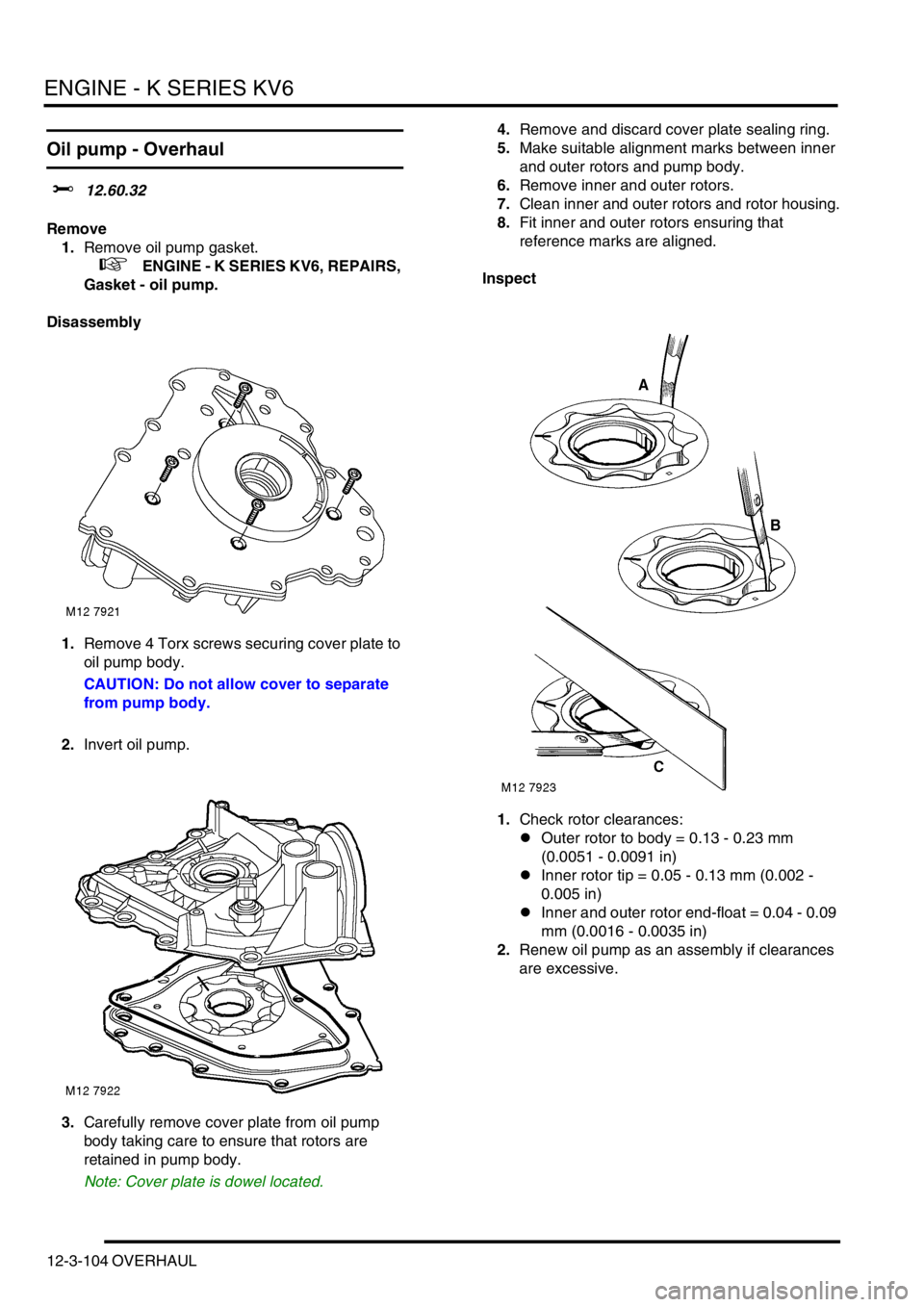
1.Remove 4 Torx screws securing cover plate to
oil pump body.
CAUTION: Do not allow cover to separate
from pump body.
2.Invert oil pump.
3.Carefully remove cover plate from oil pump
body taking care to ensure that rotors are
retained in pump body.
Note: Cover plate is dowel located.4.Remove and discard cover plate sealing ring.
5.Make suitable alignment marks between inner
and outer rotors and pump body.
6.Remove inner and outer rotors.
7.Clean inner and outer rotors and rotor housing.
8.Fit inner and outer rotors ensuring that
reference marks are aligned.
Inspect
1.Check rotor clearances:
lOuter rotor to body = 0.13 - 0.23 mm
(0.0051 - 0.0091 in)
lInner rotor tip = 0.05 - 0.13 mm (0.002 -
0.005 in)
lInner and outer rotor end-float = 0.04 - 0.09
mm (0.0016 - 0.0035 in)
2.Renew oil pump as an assembly if clearances
are excessive.
Page 282 of 1007
ENGINE - K SERIES KV6
OVERHAUL 12-3-105
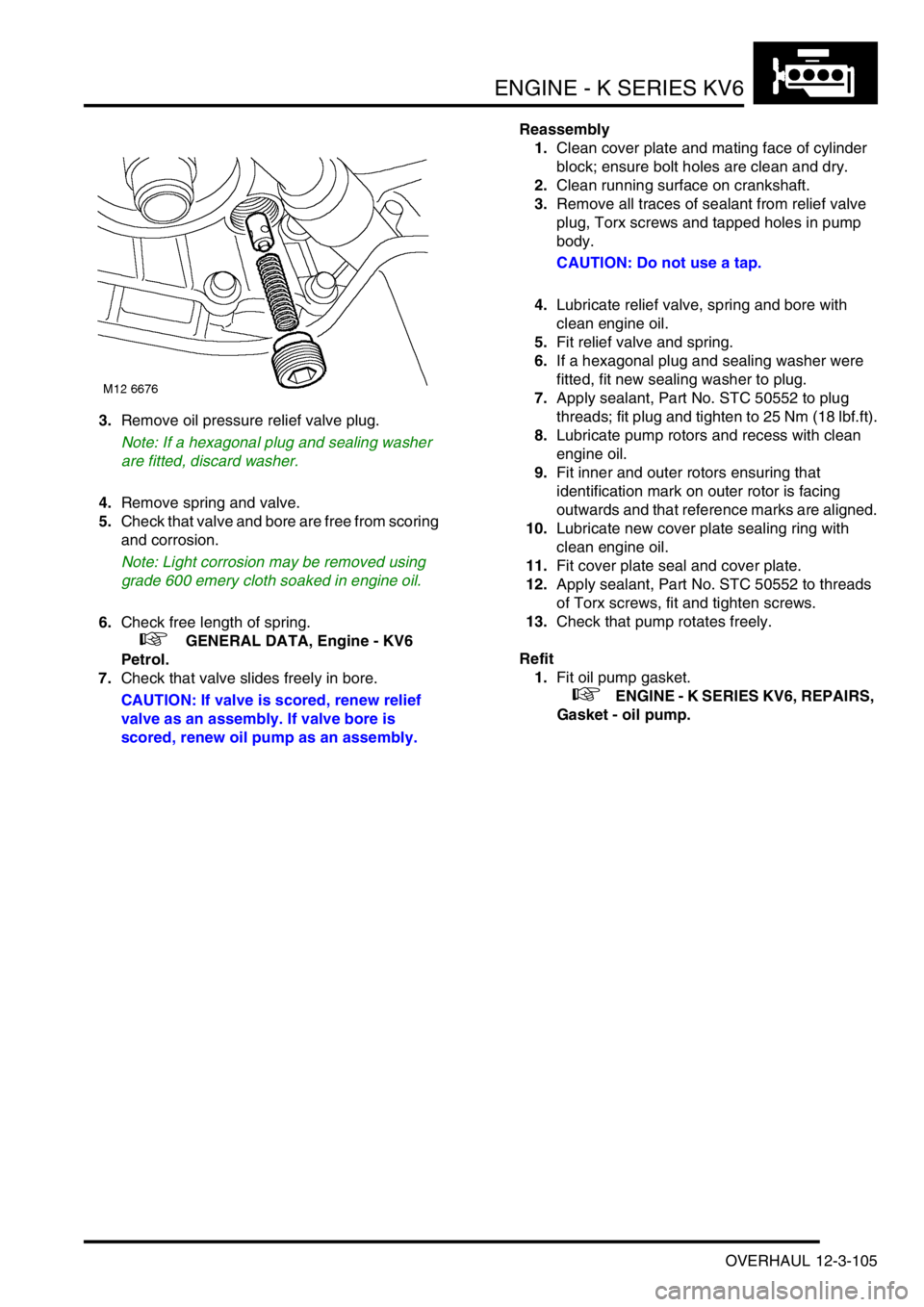
3.Remove oil pressure relief valve plug.
Note: If a hexagonal plug and sealing washer
are fitted, discard washer.
4.Remove spring and valve.
5.Check that valve and bore are free from scoring
and corrosion.
Note: Light corrosion may be removed using
grade 600 emery cloth soaked in engine oil.
6.Check free length of spring.
+ GENERAL DATA, Engine - KV6
Petrol.
7.Check that valve slides freely in bore.
CAUTION: If valve is scored, renew relief
valve as an assembly. If valve bore is
scored, renew oil pump as an assembly.Reassembly
1.Clean cover plate and mating face of cylinder
block; ensure bolt holes are clean and dry.
2.Clean running surface on crankshaft.
3.Remove all traces of sealant from relief valve
plug, Torx screws and tapped holes in pump
body.
CAUTION: Do not use a tap.
4.Lubricate relief valve, spring and bore with
clean engine oil.
5.Fit relief valve and spring.
6.If a hexagonal plug and sealing washer were
fitted, fit new sealing washer to plug.
7.Apply sealant, Part No. STC 50552 to plug
threads; fit plug and tighten to 25 Nm (18 lbf.ft).
8.Lubricate pump rotors and recess with clean
engine oil.
9.Fit inner and outer rotors ensuring that
identification mark on outer rotor is facing
outwards and that reference marks are aligned.
10.Lubricate new cover plate sealing ring with
clean engine oil.
11.Fit cover plate seal and cover plate.
12.Apply sealant, Part No. STC 50552 to threads
of Torx screws, fit and tighten screws.
13.Check that pump rotates freely.
Refit
1.Fit oil pump gasket.
+ ENGINE - K SERIES KV6, REPAIRS,
Gasket - oil pump.
Page 286 of 1007
ENGINE - K SERIES KV6
OVERHAUL 12-3-109
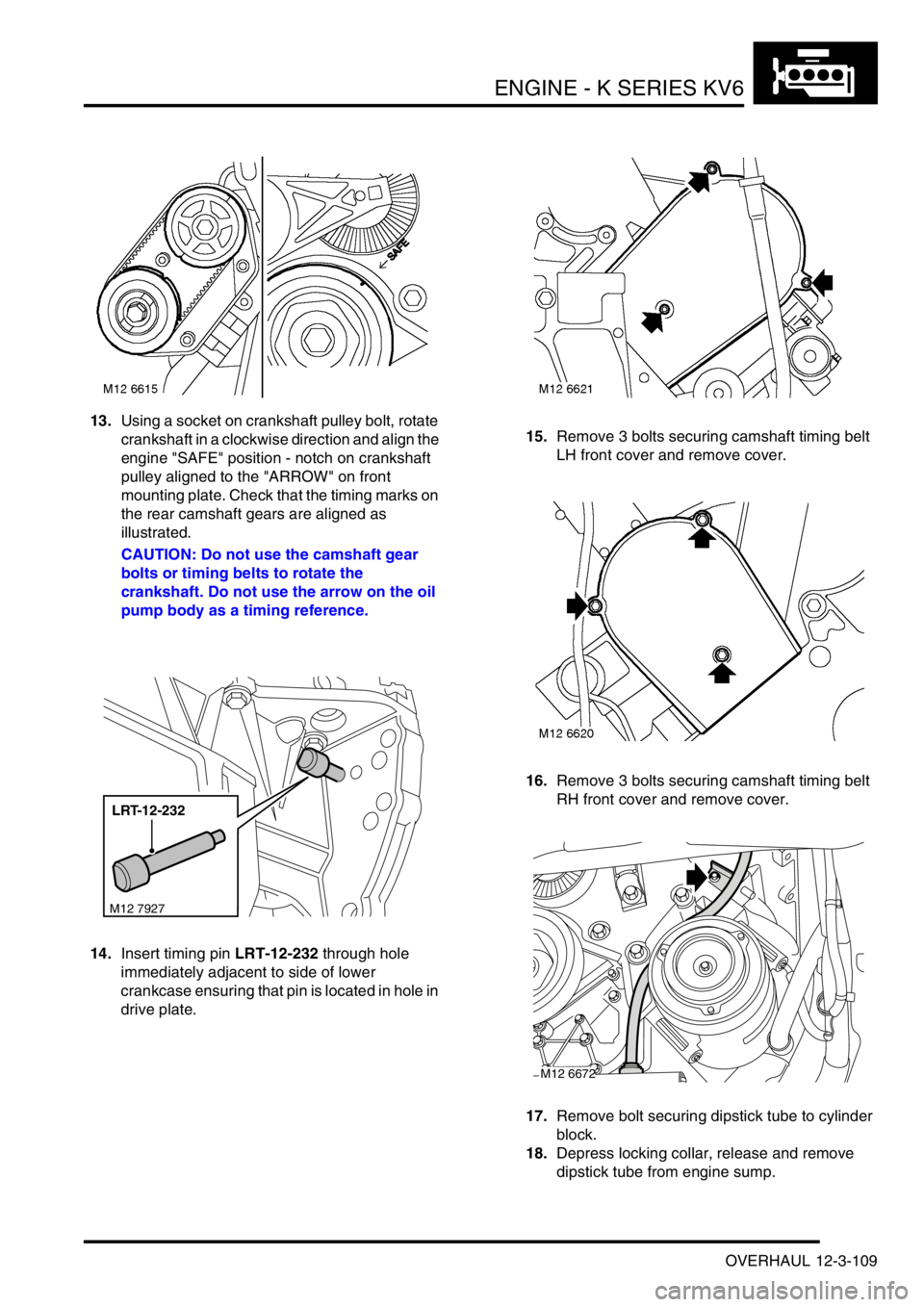
13.Using a socket on crankshaft pulley bolt, rotate
crankshaft in a clockwise direction and align the
engine "SAFE" position - notch on crankshaft
pulley aligned to the "ARROW" on front
mounting plate. Check that the timing marks on
the rear camshaft gears are aligned as
illustrated.
CAUTION: Do not use the camshaft gear
bolts or timing belts to rotate the
crankshaft. Do not use the arrow on the oil
pump body as a timing reference.
14.Insert timing pin LRT-12-232 through hole
immediately adjacent to side of lower
crankcase ensuring that pin is located in hole in
drive plate.15.Remove 3 bolts securing camshaft timing belt
LH front cover and remove cover.
16.Remove 3 bolts securing camshaft timing belt
RH front cover and remove cover.
17.Remove bolt securing dipstick tube to cylinder
block.
18.Depress locking collar, release and remove
dipstick tube from engine sump.
LRT-12-232
M12 7927
M12 6672
Page 288 of 1007
ENGINE - K SERIES KV6
OVERHAUL 12-3-111
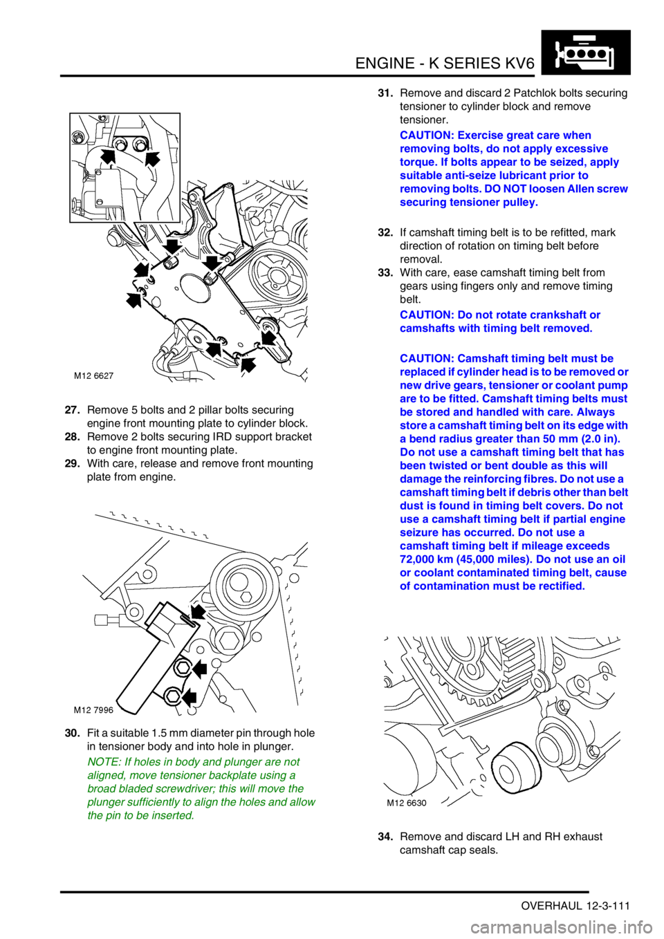
27.Remove 5 bolts and 2 pillar bolts securing
engine front mounting plate to cylinder block.
28.Remove 2 bolts securing IRD support bracket
to engine front mounting plate.
29.With care, release and remove front mounting
plate from engine.
30.Fit a suitable 1.5 mm diameter pin through hole
in tensioner body and into hole in plunger.
NOTE: If holes in body and plunger are not
aligned, move tensioner backplate using a
broad bladed screwdriver; this will move the
plunger sufficiently to align the holes and allow
the pin to be inserted.31.Remove and discard 2 Patchlok bolts securing
tensioner to cylinder block and remove
tensioner.
CAUTION: Exercise great care when
removing bolts, do not apply excessive
torque. If bolts appear to be seized, apply
suitable anti-seize lubricant prior to
removing bolts. DO NOT loosen Allen screw
securing tensioner pulley.
32.If camshaft timing belt is to be refitted, mark
direction of rotation on timing belt before
removal.
33.With care, ease camshaft timing belt from
gears using fingers only and remove timing
belt.
CAUTION: Do not rotate crankshaft or
camshafts with timing belt removed.
CAUTION: Camshaft timing belt must be
replaced if cylinder head is to be removed or
new drive gears, tensioner or coolant pump
are to be fitted. Camshaft timing belts must
be stored and handled with care. Always
store a camshaft timing belt on its edge with
a bend radius greater than 50 mm (2.0 in).
Do not use a camshaft timing belt that has
been twisted or bent double as this will
damage the reinforcing fibres. Do not use a
camshaft timing belt if debris other than belt
dust is found in timing belt covers. Do not
use a camshaft timing belt if partial engine
seizure has occurred. Do not use a
camshaft timing belt if mileage exceeds
72,000 km (45,000 miles). Do not use an oil
or coolant contaminated timing belt, cause
of contamination must be rectified.
34.Remove and discard LH and RH exhaust
camshaft cap seals.
Page 289 of 1007
ENGINE - K SERIES KV6
12-3-112 OVERHAUL
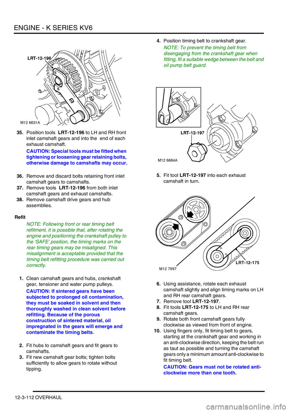
35.Position tools LRT-12-196 to LH and RH front
inlet camshaft gears and into the end of each
exhaust camshaft.
CAUTION: Special tools must be fitted when
tightening or loosening gear retaining bolts,
otherwise damage to camshafts may occur.
36.Remove and discard bolts retaining front inlet
camshaft gears to camshafts.
37.Remove tools LRT-12-196 from both inlet
camshaft gears and exhaust camshafts.
38.Remove camshaft drive gears and hub
assemblies.
Refit
NOTE: Following front or rear timing belt
refitment, it is possible that, after rotating the
engine and positioning the crankshaft pulley to
the 'SAFE' position, the timing marks on the
rear timing gears may be misaligned. This
misalignment is acceptable provided that the
timing belt refitting procedure was carried out
correctly.
1.Clean camshaft gears and hubs, crankshaft
gear, tensioner and water pump pulleys.
CAUTION: If sintered gears have been
subjected to prolonged oil contamination,
they must be soaked in solvent and then
thoroughly washed in clean solvent before
refitting. Because of the porous
construction of sintered material, oil
impregnated in the gears will emerge and
contaminate the timing belts.
2.Fit hubs to camshaft gears and fit gears to
camshafts.
3.Fit new camshaft gear bolts; tighten bolts
sufficiently to allow gears to rotate without
tipping.4.Position timing belt to crankshaft gear.
NOTE: To prevent the timing belt from
disengaging from the crankshaft gear when
fitting, fit a suitable wedge between the belt and
oil pump belt guard.
5.Fit tool LRT-12-197 into each exhaust
camshaft in turn.
6.Using assistance, rotate each exhaust
camshaft slightly and align timing marks on LH
and RH rear camshaft gears.
7.Remove tool LRT-12-197.
8.Fit tools LRT-12-175 to LH and RH rear
camshaft gears.
9.Rotate both front camshaft gears fully
clockwise as viewed from front of engine.
10.Using fingers only, fit timing belt to gears,
starting at the crankshaft gear and working in
an anti-clockwise direction, keeping the belt run
as taut as possible and turning the camshaft
gears only a minimum amount anti-clockwise to
fit timing belt.
CAUTION: Gears must not be rotated anti-
clockwise more than one tooth.
Page 290 of 1007
ENGINE - K SERIES KV6
OVERHAUL 12-3-113
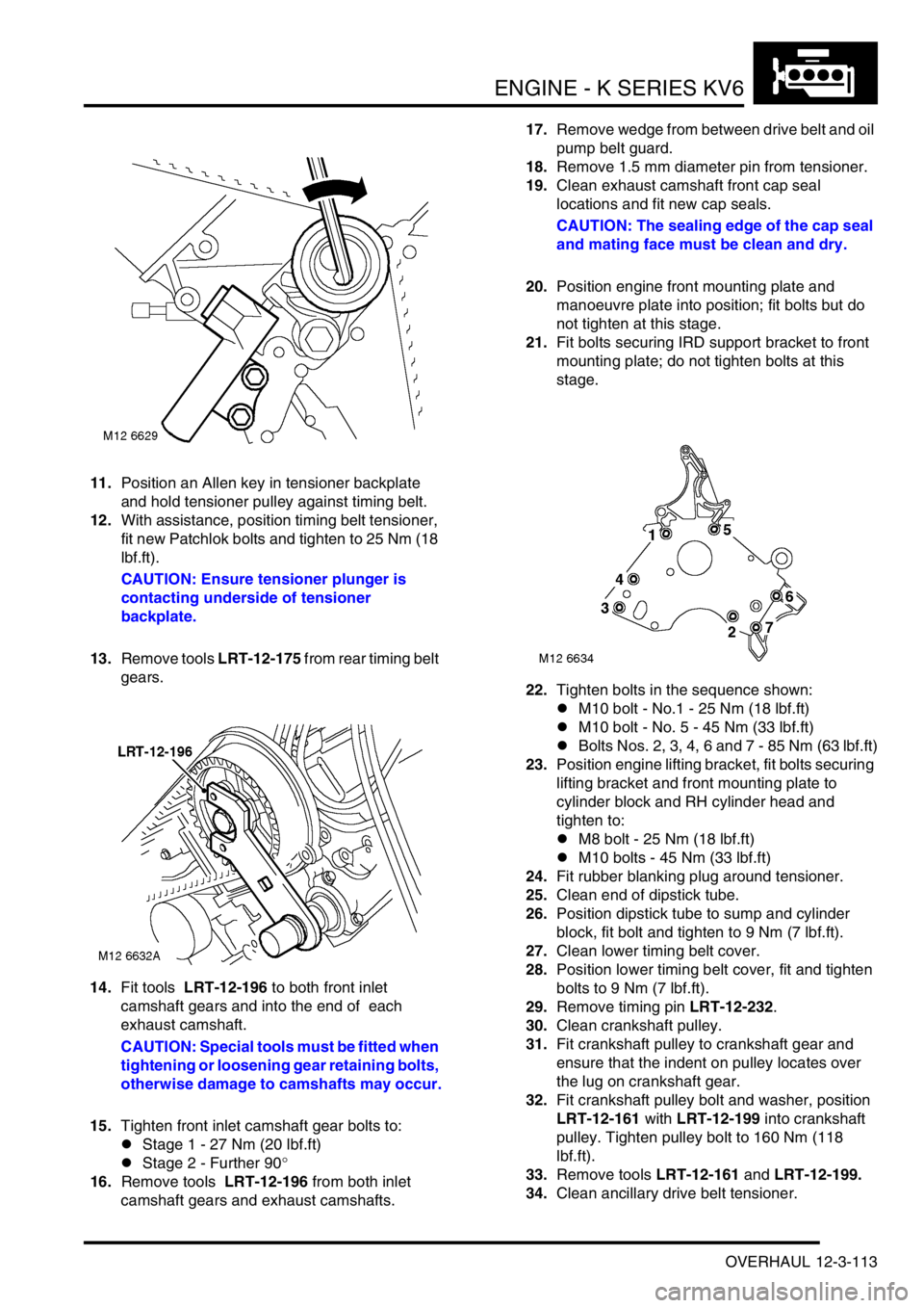
11.Position an Allen key in tensioner backplate
and hold tensioner pulley against timing belt.
12.With assistance, position timing belt tensioner,
fit new Patchlok bolts and tighten to 25 Nm (18
lbf.ft).
CAUTION: Ensure tensioner plunger is
contacting underside of tensioner
backplate.
13.Remove tools LRT-12-175 from rear timing belt
gears.
14.Fit tools LRT-12-196 to both front inlet
camshaft gears and into the end of each
exhaust camshaft.
CAUTION: Special tools must be fitted when
tightening or loosening gear retaining bolts,
otherwise damage to camshafts may occur.
15.Tighten front inlet camshaft gear bolts to:
lStage 1 - 27 Nm (20 lbf.ft)
lStage 2 - Further 90°
16.Remove tools LRT-12-196 from both inlet
camshaft gears and exhaust camshafts.17.Remove wedge from between drive belt and oil
pump belt guard.
18.Remove 1.5 mm diameter pin from tensioner.
19.Clean exhaust camshaft front cap seal
locations and fit new cap seals.
CAUTION: The sealing edge of the cap seal
and mating face must be clean and dry.
20.Position engine front mounting plate and
manoeuvre plate into position; fit bolts but do
not tighten at this stage.
21.Fit bolts securing IRD support bracket to front
mounting plate; do not tighten bolts at this
stage.
22.Tighten bolts in the sequence shown:
lM10 bolt - No.1 - 25 Nm (18 lbf.ft)
lM10 bolt - No. 5 - 45 Nm (33 lbf.ft)
lBolts Nos. 2, 3, 4, 6 and 7 - 85 Nm (63 lbf.ft)
23.Position engine lifting bracket, fit bolts securing
lifting bracket and front mounting plate to
cylinder block and RH cylinder head and
tighten to:
lM8 bolt - 25 Nm (18 lbf.ft)
lM10 bolts - 45 Nm (33 lbf.ft)
24.Fit rubber blanking plug around tensioner.
25.Clean end of dipstick tube.
26.Position dipstick tube to sump and cylinder
block, fit bolt and tighten to 9 Nm (7 lbf.ft).
27.Clean lower timing belt cover.
28.Position lower timing belt cover, fit and tighten
bolts to 9 Nm (7 lbf.ft).
29.Remove timing pin LRT-12-232.
30.Clean crankshaft pulley.
31.Fit crankshaft pulley to crankshaft gear and
ensure that the indent on pulley locates over
the lug on crankshaft gear.
32.Fit crankshaft pulley bolt and washer, position
LRT-12-161 with LRT-12-199 into crankshaft
pulley. Tighten pulley bolt to 160 Nm (118
lbf.ft).
33.Remove tools LRT-12-161 and LRT-12-199.
34.Clean ancillary drive belt tensioner.
Page 326 of 1007
FUEL DELIVERY SYSTEM - PETROL
ADJUSTMENTS 19-2-5
Fuel system - pressure test - KV6 - NAS
$% 19.50.13
Remove
1.Remove acoustic cover.
+ ENGINE - K SERIES KV6, REPAIRS,
Cover - engine acoustic.
2.Position absorbent cloth beneath fuel rail.
WARNING: Fuel vapour is highly flammable
and in confined spaces is also explosive
and toxic. Always have a fire extinguisher
containing foam, CO
2, gas or powder close
at hand when handling or draining fuel.
3. Up to 03MY: Remove nut and bolt securing coil
and position coil aside.
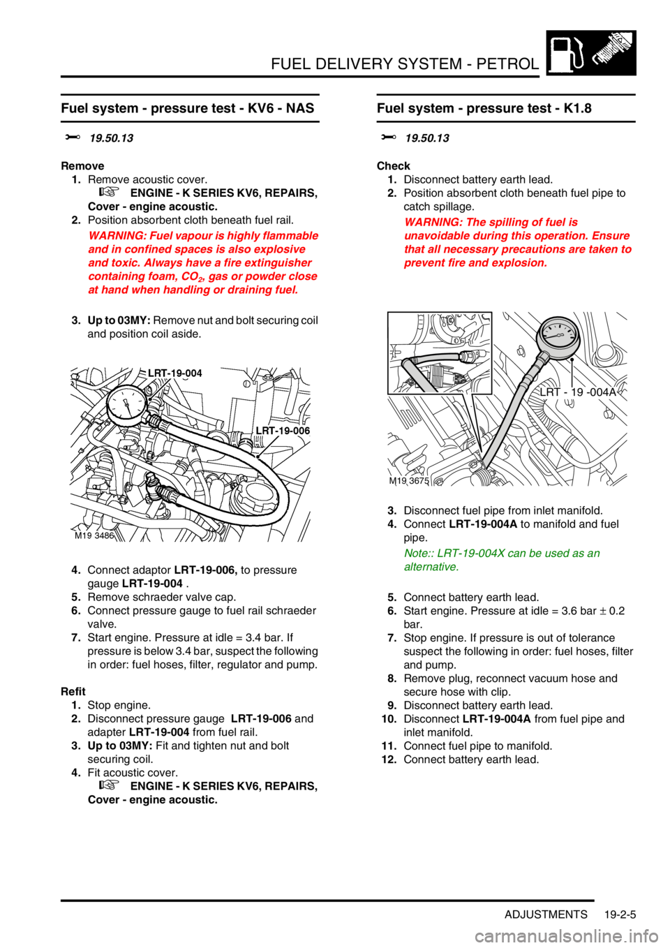
4.Connect adaptor LRT-19-006, to pressure
gauge LRT-19-004 .
5.Remove schraeder valve cap.
6.Connect pressure gauge to fuel rail schraeder
valve.
7.Start engine. Pressure at idle = 3.4 bar. If
pressure is below 3.4 bar, suspect the following
in order: fuel hoses, filter, regulator and pump.
Refit
1.Stop engine.
2.Disconnect pressure gauge LRT-19-006 and
adapter LRT-19-004 from fuel rail.
3. Up to 03MY: Fit and tighten nut and bolt
securing coil.
4.Fit acoustic cover.
+ ENGINE - K SERIES KV6, REPAIRS,
Cover - engine acoustic.
Fuel system - pressure test - K1.8
$% 19.50.13
Check
1.Disconnect battery earth lead.
2.Position absorbent cloth beneath fuel pipe to
catch spillage.
WARNING: The spilling of fuel is
unavoidable during this operation. Ensure
that all necessary precautions are taken to
prevent fire and explosion.
3.Disconnect fuel pipe from inlet manifold.
4.Connect LRT-19-004A to manifold and fuel
pipe.
Note:: LRT-19-004X can be used as an
alternative.
5.Connect battery earth lead.
6.Start engine. Pressure at idle = 3.6 bar ± 0.2
bar.
7.Stop engine. If pressure is out of tolerance
suspect the following in order: fuel hoses, filter
and pump.
8.Remove plug, reconnect vacuum hose and
secure hose with clip.
9.Disconnect battery earth lead.
10.Disconnect LRT-19-004A from fuel pipe and
inlet manifold.
11.Connect fuel pipe to manifold.
12.Connect battery earth lead.
LRT - 19 -004A
M19 3675
Page 357 of 1007
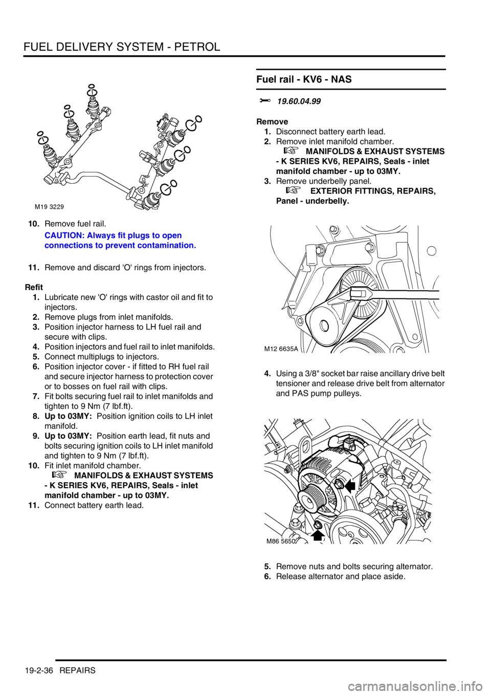
FUEL DELIVERY SYSTEM - PETROL
19-2-36 REPAIRS
10.Remove fuel rail.
CAUTION: Always fit plugs to open
connections to prevent contamination.
11.Remove and discard 'O' rings from injectors.
Refit
1.Lubricate new 'O' rings with castor oil and fit to
injectors.
2.Remove plugs from inlet manifolds.
3.Position injector harness to LH fuel rail and
secure with clips.
4.Position injectors and fuel rail to inlet manifolds.
5.Connect multiplugs to injectors.
6.Position injector cover - if fitted to RH fuel rail
and secure injector harness to protection cover
or to bosses on fuel rail with clips.
7.Fit bolts securing fuel rail to inlet manifolds and
tighten to 9 Nm (7 lbf.ft).
8. Up to 03MY: Position ignition coils to LH inlet
manifold.
9. Up to 03MY: Position earth lead, fit nuts and
bolts securing ignition coils to LH inlet manifold
and tighten to 9 Nm (7 lbf.ft).
10.Fit inlet manifold chamber.
+ MANIFOLDS & EXHAUST SYSTEMS
- K SERIES KV6, REPAIRS, Seals - inlet
manifold chamber - up to 03MY.
11.Connect battery earth lead.
Fuel rail - KV6 - NAS
$% 19.60.04.99
Remove
1.Disconnect battery earth lead.
2.Remove inlet manifold chamber.
+ MANIFOLDS & EXHAUST SYSTEMS
- K SERIES KV6, REPAIRS, Seals - inlet
manifold chamber - up to 03MY.
3.Remove underbelly panel.
+ EXTERIOR FITTINGS, REPAIRS,
Panel - underbelly.
4.Using a 3/8" socket bar raise ancillary drive belt
tensioner and release drive belt from alternator
and PAS pump pulleys.
5.Remove nuts and bolts securing alternator.
6.Release alternator and place aside.
Page 446 of 1007
AUTOMATIC GEARBOX - JATCO
REPAIRS 44-11
Oil seal - torque converter
$% 44.17.11
Remove
1.Remove gearbox assembly.
+ AUTOMATIC GEARBOX - JATCO,
REPAIRS, Gearbox - KV6.
+ AUTOMATIC GEARBOX - JATCO,
REPAIRS, Gearbox - Td4.
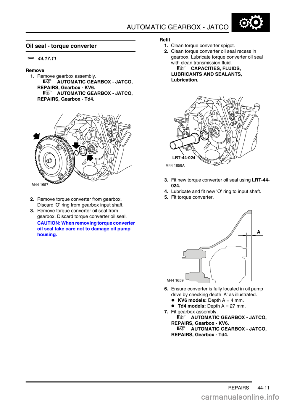
2.Remove torque converter from gearbox.
Discard 'O' ring from gearbox input shaft.
3.Remove torque converter oil seal from
gearbox. Discard torque converter oil seal.
CAUTION: When removing torque converter
oil seal take care not to damage oil pump
housing.Refit
1.Clean torque converter spigot.
2.Clean torque converter oil seal recess in
gearbox. Lubricate torque converter oil seal
with clean transmission fluid.
+ CAPACITIES, FLUIDS,
LUBRICANTS AND SEALANTS,
Lubrication.
3.Fit new torque converter oil seal using LRT-44-
024.
4.Lubricate and fit new 'O' ring to input shaft.
5.Fit torque converter.
6.Ensure converter is fully located in oil pump
drive by checking depth 'A' as illustrated.
lKV6 models: Depth A = 4 mm.
lTd4 models: Depth A = 27 mm.
7.Fit gearbox assembly.
+ AUTOMATIC GEARBOX - JATCO,
REPAIRS, Gearbox - KV6.
+ AUTOMATIC GEARBOX - JATCO,
REPAIRS, Gearbox - Td4.
M44 1659
A