ESP LAND ROVER FRELANDER 2 2006 Repair Manual
[x] Cancel search | Manufacturer: LAND ROVER, Model Year: 2006, Model line: FRELANDER 2, Model: LAND ROVER FRELANDER 2 2006Pages: 3229, PDF Size: 78.5 MB
Page 2997 of 3229

Index
277
R
Track selection . . . . . . . . . . . . . . . . . . . . 246
Traction control . . . . . . . . . . . . . . . . . . . . 139
Traffic information control . . . . . . . . . . . 226 Traffic Programme (TP) preference . . 227
Transmission Technical specifications . . . . . . . . . . . 122
Transporting the vehicle . . . . . . . . . . . . . 208
Trip computer . . . . . . . . . . . . . . . . . . . . . . 99
Type approvals . . . . . . . . . . . . . . . . . . . . 215
Declarations of conformity . . . . . . . . . 215
Tyre care . . . . . . . . . . . . . . . . . . . . . . . . . 177 Age degradation . . . . . . . . . . . . . . . . . 178
Directional tyres . . . . . . . . . . . . . . . . . 180
Flat spots . . . . . . . . . . . . . . . . . . . . . . 182
Pressure compensation for ambient
temperature changes . . . . . . . . . . . 182
Punctured tyres . . . . . . . . . . . . . . . . . 178
Replacement tyres . . . . . . . . . . . . . . . 179
Tyre checks. . . . . . . . . . . . . . . . . . . . . 179
Tyre pressures . . . . . . . . . . . . . . . . . . 180
Tyre wear . . . . . . . . . . . . . . . . . . . . . . 178
Tyre glossary. . . . . . . . . . . . . . . . . . . . . . 193 Terms used . . . . . . . . . . . . . . . . . . . . . 193
Tyre repair kit . . . . . . . . . . . . . . . . . . . . . 187
Checking the tyre pressure after a repair . . 191
Land Rover tyre repair kit . . . . . . . . . . 189
Land Rover tyre repair kit safety information 188
Using the Land Rover tyre repair kit . . 190
U
Using booster cables. . . . . . . . . . . . . . . . 173 Disconnecting the cables . . . . . . . . . . 173
Using cruise control . . . . . . . . . . . . . . . . 130 Engaging cruise control . . . . . . . . . . . 130
Increasing the cruise speed . . . . . . . . 131
Reducing the cruise speed . . . . . . . . . 130
Suspending cruise control . . . . . . . . . 130
Using HDC. . . . . . . . . . . . . . . . . . . . . . . . 137
HDC operation . . . . . . . . . . . . . . . . . . 137
Selecting HDC . . . . . . . . . . . . . . . . . . . 137
Warning messages . . . . . . . . . . . . . . . 138
Using seat belts during pregnancy . . . . . . 57
Using snow chains . . . . . . . . . . . . . . . . . 192 Using stability control. . . . . . . . . . . . . . . . 141
Deactivating DSC . . . . . . . . . . . . . . . . . 141
DSC . . . . . . . . . . . . . . . . . . . . . . . . . . . 141
DSC system fault . . . . . . . . . . . . . . . . . 141
Reactivating DSC . . . . . . . . . . . . . . . . . 141
Using terrain response . . . . . . . . . . . . . . . 132
Before driving off-road . . . . . . . . . . . . . 132
Driver override options . . . . . . . . . . . . 132
Terrain response messages . . . . . . . . . 134
Terrain Response operation . . . . . . . . . 133
Using the key . . . . . . . . . . . . . . . . . . . . . . . 40
Using the parking aid . . . . . . . . . . . . . . . . 127
Front PDC deactivation. . . . . . . . . . . . . 127
PDC activation . . . . . . . . . . . . . . . . . . . 127
Sensor care . . . . . . . . . . . . . . . . . . . . . 127
System fault . . . . . . . . . . . . . . . . . . . . . 127
Using the remote control . . . . . . . . . . . . . . 41 Approach lighting. . . . . . . . . . . . . . . . . . 42
Emergency alarm . . . . . . . . . . . . . . . . . . 43
Locking . . . . . . . . . . . . . . . . . . . . . . . . . 42
Remote battery . . . . . . . . . . . . . . . . . . . 43
Remote control . . . . . . . . . . . . . . . . . . . 41
Single and double locking . . . . . . . . . . . 42
Tailgate . . . . . . . . . . . . . . . . . . . . . . . . . 43
Unlocking . . . . . . . . . . . . . . . . . . . . . . . . 41
Using the telephone . . . . . . . . . . . . . . . . . 261 Ending telephone calls . . . . . . . . . . . . . 263
Making telephone calls. . . . . . . . . . . . . 262
Receiving telephone calls . . . . . . . . . . . 264
Selecting telephone mode . . . . . . . . . . 261
Telephone in-call menu . . . . . . . . . . . . 265
Voice mail . . . . . . . . . . . . . . . . . . . . . . 266
Using traction control . . . . . . . . . . . . . . . . 139
Before driving off-road . . . . . . . . . . . . . 139
Electronic Traction Control (ETC). . . . . 139
Using winter tyres . . . . . . . . . . . . . . . . . . 183
V
Vehicle build date plate . . . . . . . . . . . . . . . 210
Vehicle identification number (VIN) . . . . . 210
Vehicle identification plate . . . . . . . . . . . . 210
Vents . . . . . . . . . . . . . . . . . . . . . . . . . . . . 101
VIN . . . . . . . . . . . . . . . . . . . . . . . . . . . . . . 210
Volume control . . . . . . . . . . . . . . . . . . . . . 223 Automatic Volume Control (AVC). . . . . 223
Reset volume settings . . . . . . . . . . . . . 223
Page 3044 of 3229
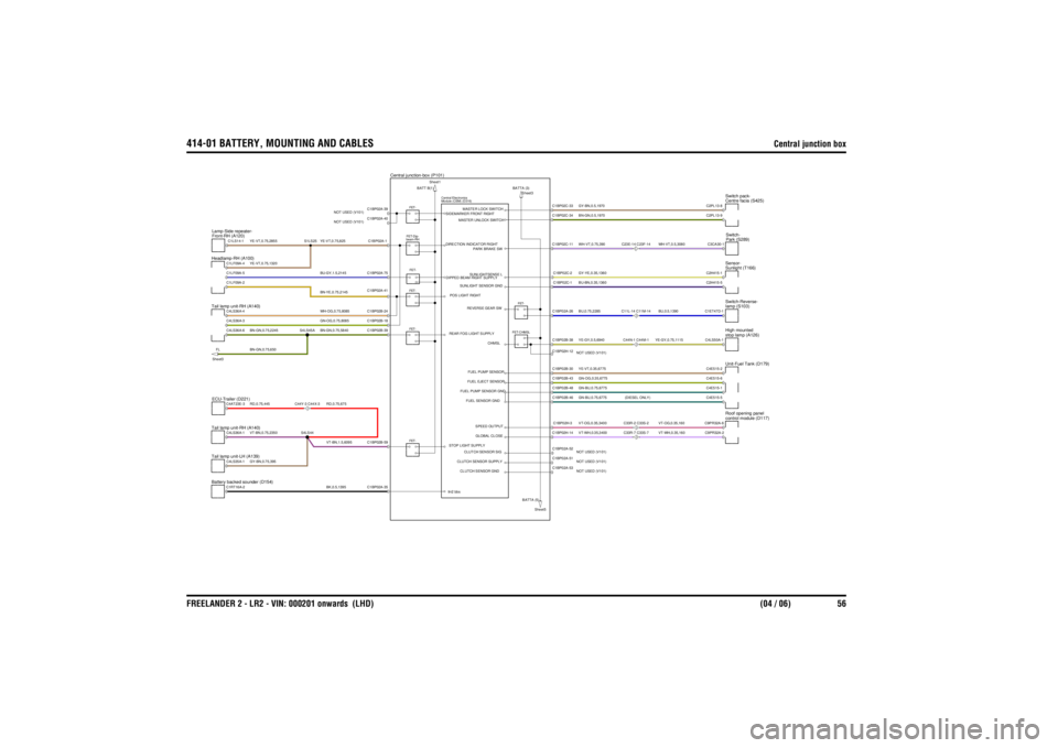
414-01 BATTERY, MOUNTING AND CABLES
Central junction box
FREELANDER 2 - LR2 - VIN: 000201 onwards (LHD) (04 / 06) 56
GY-BN,0.75,395
BK,0.5,1395BN-YE,0.75,2145WH-OG,0.75,8085GN-OG,0.75,8085BN-GN,0.75,5840RD,0.75,675VT-BN,1.5,6095
RD,0.75,445VT-BN,0.75,2350BN-GN,0.75,2245BN-GN,0.75,650
YE-VT,0.75,825BU-GY,1.5,2145
YE-VT,0.75,2855YE-VT,0.75,1320
BU-BN,0.35,1360YE-VT,0.35,6775GN-OG,0.35,6775
BU,0.5,1390
GN-BU,0.75,6775
YE-GY,0.75,1115VT-OG,0.35,160VT-WH,0.35,160
GN-BU,0.75,6775 (DIESEL ONLY)VT-OG,0.35,3400VT-WH,0.35,3400BU,0.75,2285YE-GY,0.5,6940GY-BN,0.5,1970GY-YE,0.35,1360BN-GN,0.5,1970
WH-VT,0.5,3080
WH-VT,0.75,390
Central junction-box (P101)
BATTA (5)
Sheet5
BATTA (3) Sheet3
Tail lamp unit-LH (A139)
Module (CEM) (D316)
Central Electronics
Battery backed sounder (D154)Headlamp-RH (A100)Tail lamp unit-RH (A140)ECU-Trailer (D221)
C44Y-3 C44X-3
Tail lamp unit-RH (A140)FL
Sheet3
FET-FET-FET-
FET-CHMSLFET-
FET-
Front-RH (A120)
Lamp-Side repeater-
beam-RH FET-Dip-FET-BATT B(1) Sheet1
Sunlight (T166)
Sensor-
C33R-7 C33S-7C33R-2 C33S-2C44N-1 C44M-1C11L-14 C11M-14
Unit-Fuel Tank (D179)control module (D117)
Roof opening panelstop lamp (A126)
High mountedlamp (S103)
Switch-Reverse-
C23E-14 C23F-14
Centre facia (S425)
Switch pack-Park (S289)
Switch-
C4LS35A-1
CLUTCH SENSOR SUPPLY
C1RT16A-2
C1BP02A-35
CLUTCH SENSOR GND
lin2 bbs
C1LF09A-2
SUNLIGHT SENSOR GND
C4LS36A-1C4AT23E-3
S4LS44
C4LS36A-6C4LS36A-3C4LS36A-4
S4LS45A
C1BP02B-59
CLUTCH SENSOR SIG
GLOBAL CLOSESPEED OUTPUT
STOP LIGHT SUPPLY
FUEL SENSOR GNDFUEL PUMP SENSOR GNDFUEL EJECT SENSOR
C1BP02B-39C1BP02B-18C1BP02B-24C1BP02A-41
FUEL PUMP SENSOR
REAR FOG LIGHT SUPPLY
CHMSL
REVERSE GEAR SW
POS LIGHT RIGHT
C1BP02A-40
NOT USED (V101)C1BP02A-39
NOT USED (V101)
C1LS14-1C1LF09A-4C1LF09A-5
S1LS25
C1BP02A-1C1BP02A-75
DIPPED BEAM RIGHT SUPPLYDIRECTION INDICATOR RIGHT
PARK BRAKE SWSUNLIGHTSENSE L
SIDEMARKER FRONT RIGHT
MASTER UNLOCK SWITCHMASTER LOCK SWITCH
C1BP02A-51 NOT USED (V101)C1BP02A-53NOT USED (V101)
C2H415-5
C1BP02C-1C1BP02B-30C1BP02A-52NOT USED (V101)C1BP02H-14C1BP02H-3C1BP02B-46C1BP02B-48C1BP02B-43C1BP02H-12 NOT USED (V101)C1BP02B-38C1BP02A-26
C4E515-2C9PR32A-6C9PR32A-2C4E515-5C4E515-1C4E515-6C4LS50A-1C1ET47D-1
C1BP02C-2C1BP02C-11C1BP02C-34C1BP02C-33
C2H415-1C3CA30-1C2PL13-9C2PL13-8
Page 3104 of 3229
USING THIS PUBLICATION
08/20089
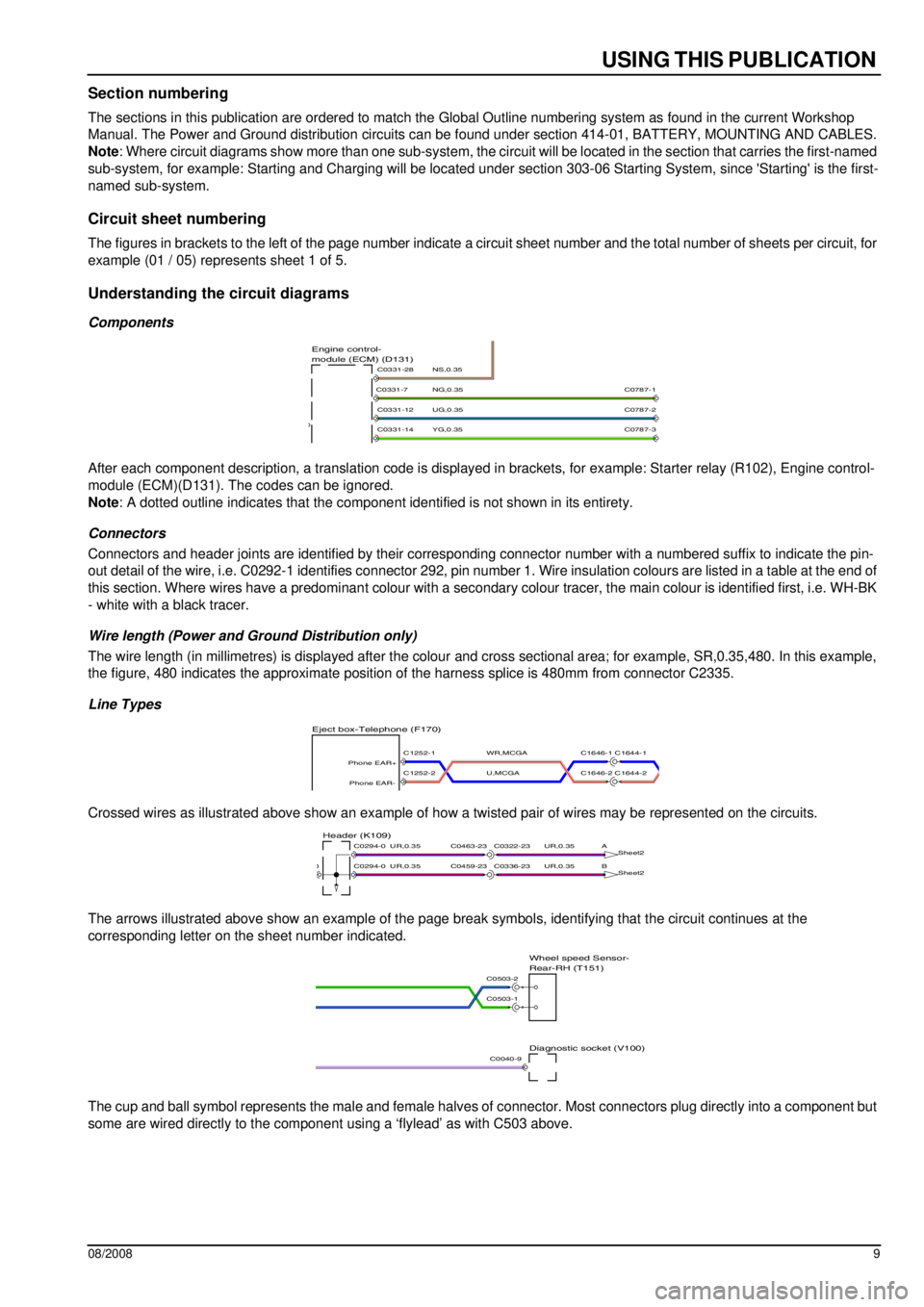
Section numbering
The sections in this publication are ordered to match the Global Outline numbering system as found in the current Workshop
Manual. The Power and Ground distribution circuits can be found under section 414-01, BATTERY, MOUNTING AND CABLES.
Note: Where circuit diagrams show more than one sub-system, the circuit will be located in the section that carries the first-named
sub-system, for example: Starting and Charging will be located under section 303-06 Starting System, since 'Starting' is the first-
named sub-system.
Circuit sheet numbering
The figures in brackets to the left of the page number indicate a circuit sheet number and the total number of sheets per circuit, for
example (01 / 05) represents sheet 1 of 5.
Understanding the circuit diagrams
Components
After each component description, a translation code is displayed in brackets, for example: Starter relay (R102), Engine control-
module (ECM)(D131). The codes can be ignored.
Note: A dotted outline indicates that the component identified is not shown in its entirety.
Connectors
Connectors and header joints are identified by their corresponding connector number with a numbered suffix to indicate the pin-
out detail of the wire, i.e. C0292-1 identifies connector 292, pin number 1. Wire insulation colours are listed in a table at the end of
this section. Where wires have a predominant colour with a secondary colour tracer, the main colour is identified first, i.e. WH-BK
- white with a black tracer.
Wire length (Power and Ground Distribution only)
The wire length (in millimetres) is displayed after the colour and cross sectional area; for example, SR,0.35,480. In this example,
the figure, 480 indicates the approximate position of the harness splice is 480mm from connector C2335.
Line Types
Crossed wires as illustrated above show an example of how a twisted pair of wires may be represented on the circuits.
The arrows illustrated above show an example of the page break symbols, identifying that the circuit continues at the
corresponding letter on the sheet number indicated.
The cup and ball symbol represents the male and female halves of connector. Most connectors plug directly into a component but
some are wired directly to the component using a ‘flylead’ as with C503 above.
YG,0.35
UG,0.35
NG,0.35
NS,0.35module (ECM) (D131) Engine control-
C0331-14
C0331-12
C0331-7
C0331-28
C0787-2
C0787-3
C0787-1
U,MCGA
WR,MCGA
Eject box-Telephone (F170)
C1646-1 C1644-1
C1646-2 C1644-2C1252-2
Phone EAR-
C1252-1
Phone EAR+
UR,0.35UR,0.35
UR,0.35UR,0.35
B
Sheet2
A
Sheet2Header (K109)
C0336-23C0459-23
C0322-23C0463-23
C0294-00
C0294-0
Diagnostic socket (V100)
Rear-RH (T151) Wheel speed Sensor-
C0503-1
C0503-2
C0040-9
Page 3150 of 3229
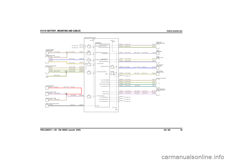
414-01 BATTERY, MOUNTING AND CABLES
Central junction box
FREELANDER 2 - LR2 - VIN: 000201 onwards (RHD) (04 / 06) 56
GY-BN,0.75,395
BK,0.5,1395BN-YE,0.75,2145WH-OG,0.75,8085GN-OG,0.75,8085BN-GN,0.75,5840RD,0.75,675VT-BN,1.5,6095
RD,0.75,445VT-BN,0.75,2350BN-GN,0.75,2245BN-GN,0.75,650
YE-VT,0.75,825BU-GY,1.5,2145
YE-VT,0.75,2855YE-VT,0.75,1320
BU-BN,0.35,1360YE-VT,0.35,6775GN-OG,0.35,6775
BU,0.5,1390
GN-BU,0.75,6775
YE-GY,0.75,1115VT-OG,0.35,160VT-WH,0.35,160
GN-BU,0.75,6775 (DIESEL ONLY)VT-OG,0.35,3400VT-WH,0.35,3400BU,0.75,2285YE-GY,0.5,6940GY-BN,0.5,1970GY-YE,0.35,1360BN-GN,0.5,1970
WH-VT,0.5,3080
WH-VT,0.75,390
Central junction-box (P101)
BATTA (5)
Sheet5
BATTA (3) Sheet3
Tail lamp unit-LH (A139)
Module (CEM) (D316)
Central Electronics
Battery backed sounder (D154)Headlamp-RH (A100)Tail lamp unit-RH (A140)ECU-Trailer (D221)
C44Y-3 C44X-3
Tail lamp unit-RH (A140)FL
Sheet3
FET-FET-FET-
FET-CHMSLFET-
FET-
Front-RH (A120)
Lamp-Side repeater-
beam-RH FET-Dip-FET-BATT B(1) Sheet1
Sunlight (T166)
Sensor-
C33R-7 C33S-7C33R-2 C33S-2C44N-1 C44M-1C11L-14 C11M-14
Unit-Fuel Tank (D179)control module (D117)
Roof opening panelstop lamp (A126)
High mountedlamp (S103)
Switch-Reverse-
C23E-14 C23F-14
Centre facia (S425)
Switch pack-Park (S289)
Switch-
C4LS35A-1
CLUTCH SENSOR SUPPLY
C1RT16A-2
C1BP02A-35
CLUTCH SENSOR GND
lin2 bbs
C1LF09A-2
SUNLIGHT SENSOR GND
C4LS36A-1C4AT23E-3
S4LS44
C4LS36A-6C4LS36A-3C4LS36A-4
S4LS45A
C1BP02B-59
CLUTCH SENSOR SIG
GLOBAL CLOSESPEED OUTPUT
STOP LIGHT SUPPLY
FUEL SENSOR GNDFUEL PUMP SENSOR GNDFUEL EJECT SENSOR
C1BP02B-39C1BP02B-18C1BP02B-24C1BP02A-41
FUEL PUMP SENSOR
REAR FOG LIGHT SUPPLY
CHMSL
REVERSE GEAR SW
POS LIGHT RIGHT
C1BP02A-40
NOT USED (V101)C1BP02A-39
NOT USED (V101)
C1LS14-1C1LF09A-4C1LF09A-5
S1LS25
C1BP02A-1C1BP02A-75
DIPPED BEAM RIGHT SUPPLYDIRECTION INDICATOR RIGHT
PARK BRAKE SWSUNLIGHTSENSE L
SIDEMARKER FRONT RIGHT
MASTER UNLOCK SWITCHMASTER LOCK SWITCH
C1BP02A-51 NOT USED (V101)C1BP02A-53NOT USED (V101)
C2H415-5
C1BP02C-1C1BP02B-30C1BP02A-52NOT USED (V101)C1BP02H-14C1BP02H-3C1BP02B-46C1BP02B-48C1BP02B-43C1BP02H-12 NOT USED (V101)C1BP02B-38C1BP02A-26
C4E515-2C9PR32A-6C9PR32A-2C4E515-5C4E515-1C4E515-6C4LS50A-1C1ET47D-1
C1BP02C-2C1BP02C-11C1BP02C-34C1BP02C-33
C2H415-1C3CA30-1C2PL13-9C2PL13-8
Page 3209 of 3229
USING THIS PUBLICATION
08/2008 9
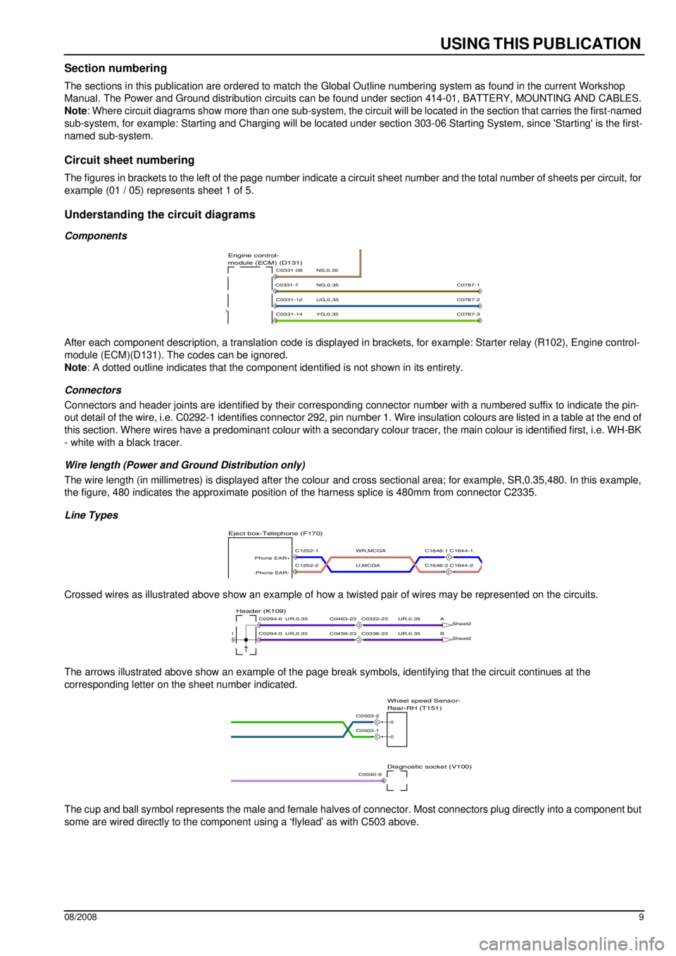
Section numbering
The sections in this publication are ordered to match the Global Outline numbering system as found in the current Workshop
Manual. The Power and Ground distribution circuits can be found under section 414-01, BATTERY, MOUNTING AND CABLES.
Note : Where circuit diagrams show more than one sub-system, the circ uit will be located in the section that carries the first-named
sub-system, for example: Starting and Charging will be located unde r section 303-06 Starting System, since 'Starting' is the first-
named sub-system.
Circuit sheet numbering
The figures in brackets to the left of the page number indicate a circuit sheet number and the total number of sheets per circu it, for
example (01 / 05) represents sheet 1 of 5.
Understanding the circuit diagrams
Components
After each component description, a translation code is displayed in brackets, for example: Starter relay (R102), Engine control-
module (ECM)(D131). The codes can be ignored.
Note : A dotted outline indicates that the compone nt identified is not shown in its entirety.
Connectors
Connectors and header joints are identified by their corresponding connector number wit h a numbered suffix to indicate the pin-
out detail of the wire, i.e. C0292-1 identifies connector 292, pin number 1. Wire insulation colours are listed in a table at t he end of
this section. Where wires have a predominan t colour with a secondary colour tracer, the main colour is identified first, i.e. WH-BK
- white with a black tracer.
Wire length (Power and Ground Distribution only)
The wire length (in millimetres) is displayed after the colour and cross sectional area; for example, SR,0.35,480. In this example,
the figure, 480 indicates the approximate position of the harness splice is 480mm from connector C2335.
Line Types
Crossed wires as illustrated above show an example of how a twisted pair of wires may be represented on the circuits.
The arrows illustrated above show an example of the page break symbols, identifying that the circuit continues at the
corresponding letter on the sheet number indicated.
The cup and ball symbol represents the male and female halves of connector. Most connectors plug directly into a component but
some are wired directly to the component using a ‘flylead’ as with C503 above.
YG,0.35
UG,0.35
NG,0.35
NS,0.35module (ECM) (D131)
Engine control-
C0331-14
C0331-12
C0331-7
C0331-28
C0787-2
C0787-3
C0787-1
U,MCGA
WR,MCGA
Eject box-Telephone (F170)
C1646-1 C1644-1
C1646-2 C1644-2C1252-2
Phone EAR-
C1252-1
Phone EAR+
UR,0.35UR,0.35
UR,0.35UR,0.35
B Sheet2
A
Sheet2Header (K109)
C0336-23C0459-23
C0322-23C0463-23
C0294-00
C0294-0
Diagnostic socket (V100)
Rear-RH (T151)
Wheel speed Sensor-
C0503-1
C0503-2
C0040-9