width LAND ROVER FRELANDER 2 2006 Repair Manual
[x] Cancel search | Manufacturer: LAND ROVER, Model Year: 2006, Model line: FRELANDER 2, Model: LAND ROVER FRELANDER 2 2006Pages: 3229, PDF Size: 78.5 MB
Page 31 of 3229

Invert the compres s or and gravi ty drain the oi l into a calibrated meas uri ng cyl inder. Rotat e t he compres sor clut ch tomake s ure the compres s or is complet el y drai ned.Note the quanti ty of oi l drained (Y cm³).Calculate the quanti ty of oi l to be drained from t he new compres sor us ing t he fol lowi ng formula:X cm³ — (Y cm³ +20 cm³) = Q cm³Remove the drain pl ug from the new compres s or and drain Q cm3 of oi l. ins t al l and tight en t he compres sor drai nplug.
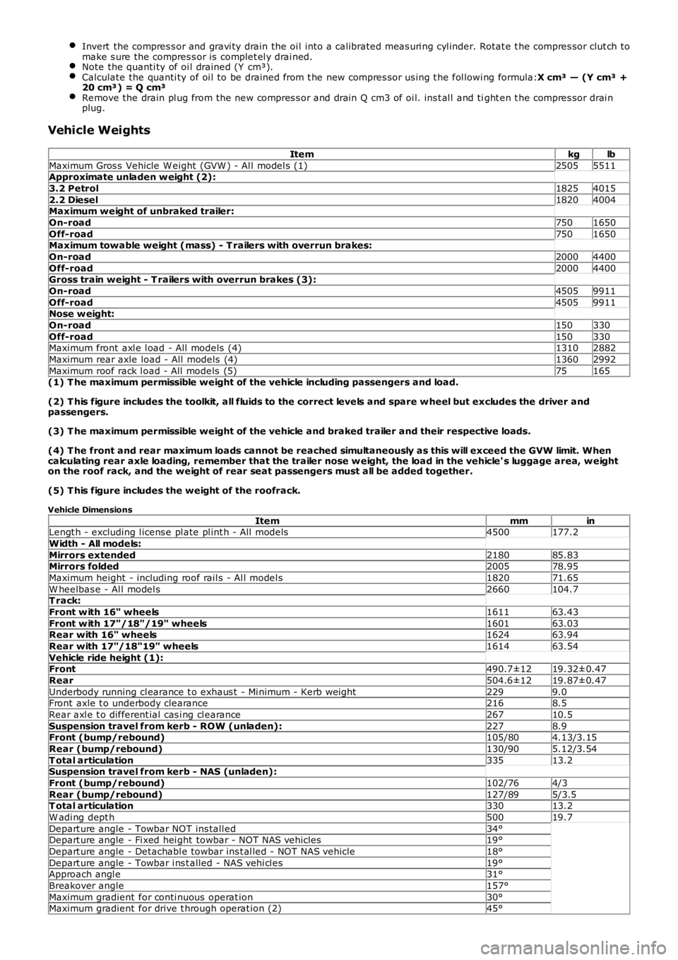
Vehicle Weights
Itemkglb
Maximum Gros s Vehicle W eight (GVW ) - Al l model s (1)25055511Approximate unladen w eight (2):
3.2 Petrol18254015
2.2 Diesel18204004Maximum weight of unbraked trailer:
On-road7501650
Off-road7501650Maximum towable weight (mass) - T railers with overrun brakes:
On-road20004400
Off-road20004400Gross train weight - T railers with overrun brakes (3):
On-road45059911
Off-road45059911Nose w eight:
On-road150330
Off-road150330Maximum front axl e l oad - All models (4)13102882
Maximum rear axle load - All models (4)13602992
Maximum roof rack l oad - All models (5)75165(1) T he maximum permissible weight of the vehicle including passengers and load.
(2) T his figure includes the toolkit, all fluids to the correct levels and spare w heel but excludes the driver andpassengers.
(3) T he maximum permissible weight of the vehicle and braked trailer and their respective loads.
(4) T he front and rear maximum loads cannot be reached simultaneously as this will exceed the GVW limit. Whencalculating rear axle loading, remember that the trailer nose w eight, the load in the vehicle' s luggage area, w eighton the roof rack, and the weight of rear seat passengers must all be added together.
(5) T his figure includes the weight of the roofrack.
Vehicle Dimensions
ItemmminLengt h - excluding l icens e pl ate pl int h - All models4500177.2
Width - All models:
Mirrors extended218085.83Mirrors folded200578.95
Maximum height - including roof rail s - Al l model s182071.65
W heelbas e - Al l model s2660104.7T rack:
Front w ith 16" wheels161163.43
Front w ith 17"/18"/19" wheels160163.03Rear with 16" wheels162463.94
Rear with 17"/18"19" wheels161463.54
Vehicle ride height (1):Front490.7±1219.32±0.47
Rear504.6±1219.87±0.47
Underbody running cl earance t o exhaus t - Mi nimum - Kerb wei ght2299.0Front axle t o underbody clearance2168.5
Rear axl e t o different ial cas i ng cl earance26710.5
Suspension travel from kerb - ROW (unladen):2278.9Front (bump/rebound)105/804.13/3.15
Rear (bump/rebound)130/905.12/3.54
T otal articulation33513.2Suspension travel from kerb - NAS (unladen):
Front (bump/rebound)102/764/3
Rear (bump/rebound)127/895/3.5T otal articulation33013.2
W adi ng dept h50019.7
Depart ure angle - Towbar NOT ins tall ed34°Depart ure angle - Fi xed hei ght towbar - NOT NAS vehicles19°
Depart ure angle - Detachabl e towbar ins t al led - NOT NAS vehicle18°
Depart ure angle - Towbar i ns t alled - NAS vehi cl es19°Approach angl e31°
Breakover angle157°
Maximum gradient for conti nuous operat ion30°Maximum gradient for drive t hrough operat ion (2)45°
Page 2517 of 3229

The clinched fl anges on the hood, doors, t ail gat e and l iftgate mus t be s eal ed wit h cli nched flange s eal er, i f this is notalready appli ed.
Weld Components
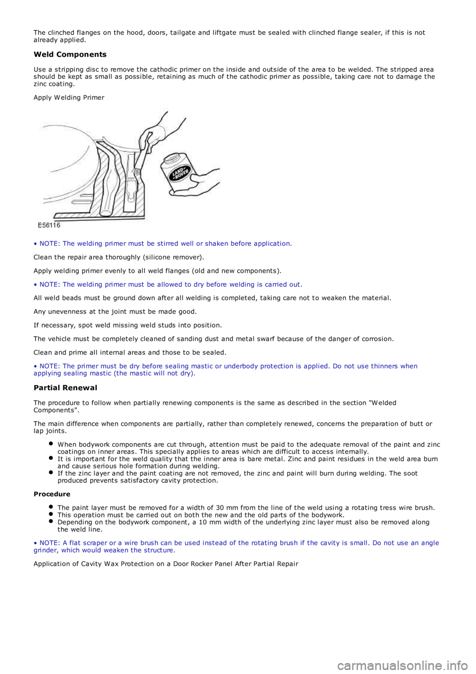
Us e a s t ri ppi ng dis c t o remove t he cathodic primer on t he i ns i de and out s ide of t he area t o be wel ded. The s t ri pped areas houl d be kept as small as poss i bl e, ret ai ning as much of t he cat hodic pri mer as poss i bl e, taking care not to damage t hezinc coat ing.
Apply W el ding Primer
• NOTE: The weldi ng pri mer must be st irred well or shaken before appl icati on.
Clean t he repair area t horoughly (s il icone remover).
Apply wel di ng pri mer evenly to al l weld flanges (ol d and new component s ).
• NOTE: The weldi ng pri mer must be allowed t o dry before welding is carried out .
All wel d beads must be ground down aft er al l welding i s complet ed, t aki ng care not to weaken the mat eri al.
Any unevenness at t he joint mus t be made good.
If necess ary, s pot weld mis s ing wel d s tuds i nt o pos it ion.
The vehi cl e mus t be complet ely cleaned of s anding dus t and met al swarf because of the danger of corrosi on.
Clean and prime al l int ernal areas and thos e t o be s ealed.
• NOTE: The pri mer mus t be dry before s eali ng mas ti c or underbody prot ect ion is appli ed. Do not us e t hinners whenappl ying s ealing mast ic (t he mas ti c wil l not dry).
Partial Renewal
The procedure t o fol low when parti all y renewing component s i s the same as descri bed in the s ecti on "W eldedComponent s".
The main difference when component s are parti ally, rat her than complet ely renewed, concerns t he preparat ion of but t orlap joint s.
W hen bodywork component s are cut t hrough, at t ent ion mus t be pai d to the adequate removal of t he paint and zinccoat ings on i nner areas . This s peci all y appl ies t o areas whi ch are di fficult t o acces s int ernall y.It is i mport ant for the wel d quali ty t hat the i nner area is bare met al. Zinc and paint resi dues in t he weld area burnand caus e s eri ous hol e format ion duri ng weldi ng.If the zinc l ayer and t he paint coat ing are not removed, the zi nc and pai nt wil l burn duri ng welding. The s ootproduced prevent s s ati sfact ory cavit y prot ect ion.
Procedure
The paint layer mus t be removed for a widt h of 30 mm from the l ine of t he weld usi ng a rotat ing t res s wi re brush.This operat ion mus t be carried out on bot h t he new and t he old part s of t he bodywork.Dependi ng on the bodywork component , a 10 mm width of the underl yi ng zinc l ayer mus t als o be removed alongt he weld l ine.
• NOTE: A flat s craper or a wire brus h can be us ed i ns t ead of the rotat ing brus h if t he cavit y i s s mall . Do not us e an angl egri nder, which would weaken t he s truct ure.
Applicati on of Cavi ty W ax Prot ect ion on a Door Rocker Panel Aft er Part ial Repai r
Page 2896 of 3229

Wheels and tyres
176
L
Wheels and tyresGENERAL INFORMATION
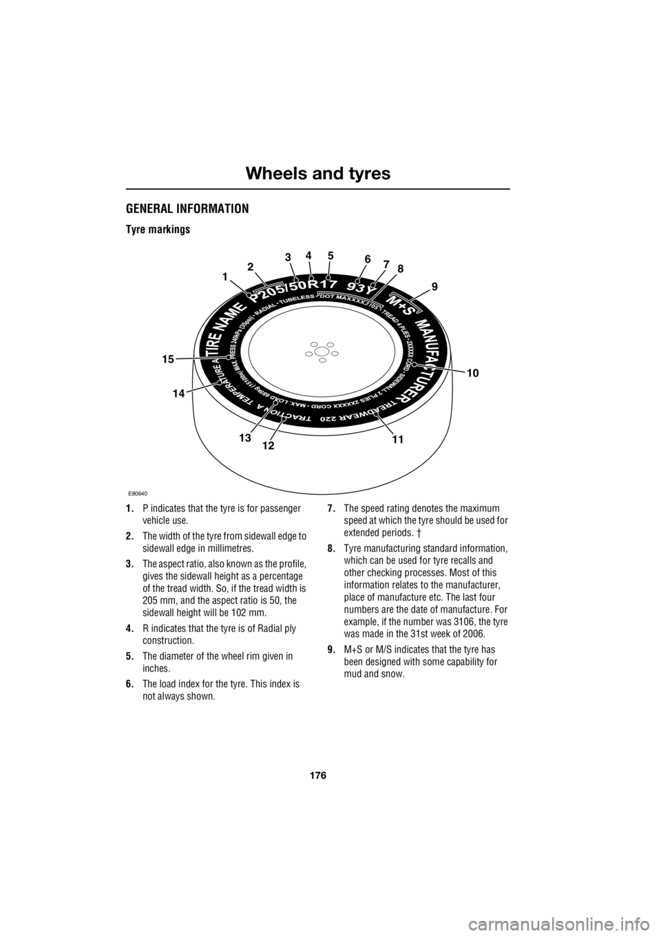
Tyre markings
1. P indicates that the tyre is for passenger
vehicle use.
2. The width of the tyre fr om sidewall edge to
sidewall edge in millimetres.
3. The aspect ratio, also known as the profile,
gives the sidewall height as a percentage
of the tread width. So, if the tread width is
205 mm, and the aspect ratio is 50, the
sidewall height will be 102 mm.
4. R indicates that the ty re is of Radial ply
construction.
5. The diameter of the wheel rim given in
inches.
6. The load index for the tyre. This index is
not always shown. 7.
The speed rating de notes the maximum
speed at which the tyre should be used for
extended periods. †
8. Tyre manufacturing standard information,
which can be used for tyre recalls and
other checking processe s. Most of this
information relates to the manufacturer,
place of manufacture etc. The last four
numbers are the date of manufacture. For
example, if the number was 3106, the tyre
was made in the 31st week of 2006.
9. M+S or M/S indicates that the tyre has
been designed with some capability for
mud and snow.
10
12345678
9
111213
14
15
E80640
Page 2933 of 3229

213
Technical specifications
R
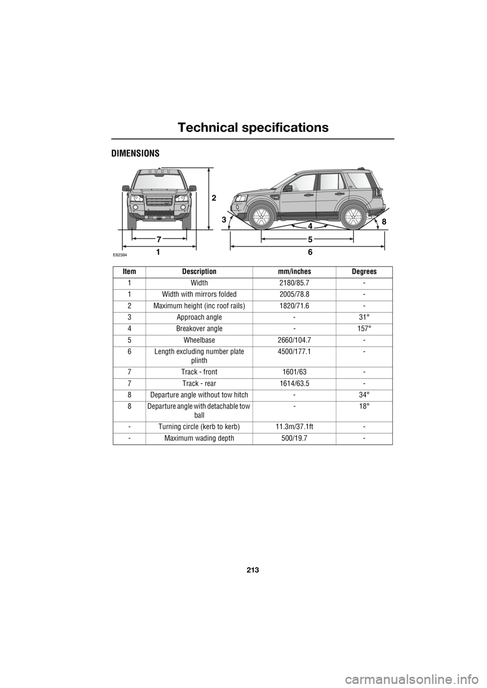
DIMENSIONS
2
E8238416
5
438
7
Item Description mm/inches Degrees 1 Width 2180/85.7 -
1 Width with mirrors folded 2005/78.8 -
2 Maximum height (inc roof rails) 1820/71.6 -
3 Approach angle - 31°
4 Breakover angle - 157°
5 Wheelbase 2660/104.7 -
6 Length excluding number plate plinth 4500/177.1 -
7 Track - front 1601/63 -
7 Track - rear 1614/63.5 -
8 Departure angle without tow hitch - 34°
8 Departure angle with detachable tow ball - 18°
- Turning circle (kerb to kerb) 11.3m/37.1ft -
- Maximum wading depth 500/19.7 -