tire type LAND ROVER FRELANDER 2 2006 Repair Manual
[x] Cancel search | Manufacturer: LAND ROVER, Model Year: 2006, Model line: FRELANDER 2, Model: LAND ROVER FRELANDER 2 2006Pages: 3229, PDF Size: 78.5 MB
Page 44 of 3229
Publi s hed: 11-May-2011
General Information - Road/Roller Testing
Des cript ion and Operat ion
Road or roll ing road t es t ing may be carri ed out for various reasons and a procedure det ail ing pre-t es t checks , throughengi ne s tarti ng and s topping, pre-driving checks , on-t es t checks to final checks on complet ion of t he tes t are given.
Unles s complete vehi cl e performance is bei ng checked, t he ful l road t est procedure need not be carried out . Ins tead, t hos eit ems part icularly relevant t o t he s yst em(s) bei ng checked can be ext racted.
Pre-Test Checks
W ARNING: If t he brake s yst em hydraul ic fluid level i s l ow, pedal travel i s exces si ve or a hydraulic leak is found, donot att empt to road t est t he vehicle unt il t he reas on for t he low fl ui d l evel, excess ive pedal travel or hydraulic leak isfound and rect ified.
It is s ugges t ed that pre-t es t and funct ional t es ts of t hose sys tems/circuit s whi ch affect t he safe and l egal operati ons oft he vehi cl e, s uch as brakes , light s and s teeri ng, should al ways be carri ed out before the road or roll ing road tes t .
Engi ne oil l evelEngi ne cool ant levelTires, for correct pres sure, compat ible types and tread patt erns , and wear wi thi n limi ts .There i s s ufficient fuel in the t ank to compl ete the t est .Check al l around the engine, t rans mis s ion and under the vehicle for oil , coolant , hydraul ic and fuel l eaks . Make anote of any apparent leaks and wipe off t he surrounding areas t o make it easi er to identi fy t he extent of the leakon complet ion of t he tes t.
Starting the Engine
• NOTE: On i nit ial dri ve away from cold and wit hi n t he fi rs t 1.5 km (1 mile), do not depress accelerat or pedal beyond halft ravel unt il t he vehi cl e has att ained a minimum s peed of 25 km/h (15 mil es /h). Never operat e at high engi ne speed or wi tht he accelerat or pedal at ful l travel whil st the engine i s cold.
With the ignition off, check:
The parking brake is appli ed.Automatic transmission: The s el ect or lever is i n 'P' - PARK.Manual transmission: The gear l ever i s in NEUTRAL.All i ns t rument gauges read zero.
With the ignition on, check:
Igni ti on cont roll ed warni ng li ght s come on.Engi ne t emperature gauge regis t ers a readi ng compat ibl e wi th t he engine t emperat ure.Fuel gauge regi st ers a reading appropriate to the fuel l evel i n t he tank.The operati on of the parki ng brake warning l ight and fl ui d l evel warni ng indicator light.
On Road Test Check:
CAUTION: At commencement of road tes ti ng, check the brake operati on while s ti ll travel li ng at low speed beforecont inuing wit h t he tes t. If t he brakes pul l to one si de, or appear to be ot herwi se fault y, do not cont inue wit h t he roadt es t unti l the fault has been found and rect ified.
The parking brake releas es completel y.Gear changing i s s mooth, and t here are no abnormal noi s es or vi brati ons from t he t rans mis s ion.The engi ne power out put is s ati s factory, accel erati on is smoot h and accel erator pedal operat ion is not s ti ff orheavy, and engi ne s peed ret urns t o idl e correctl y.There i s no exces s ive or abnormall y colored s moke from t he engi ne under normal driving, heavy l oad or overruncondi ti ons .Steering operat ion i s s moot h, accurat e, not exces s ively heavy or wit h exces s ive free pl ay or vibrat ion. Does not pul lt o one s ide and s elf centres smoot hly after corneri ng.All i ns t rument s regis t er the correct readi ngs and operate correctl y.Swit ches and controls operat e s moothl y and posi ti vel y, warning or i ndi cat or light s operate correctl y and thedirect ion i ndi cat or cont rol s elf cancels when the s t eering i s ret urned t o t he s traight ahead pos it ion.Heati ng and vent il at ion sys tems work correct ly and effect ively.Brakes operate efficientl y.
Brake Testing
Avoi d brake t es ti ng on busy roads where i t can caus e i nconveni ence or danger t o ot her road users.
CAUTION: Brake t es ti ng which i ncludes heavy brake appl icati ons should not be carri ed out wit h new brake pads /dis csunti l the component s have bedded-i n. New brake fri ct ion component s wi ll not reach ful l efficiency unt il t he beddi ng-inprocess is complet e. Not e t hat when new parking brake shoes or rear brake di scs have been ins t al led, it i s es sent ial thatt he 'beddi ng-in' procedure i s carri ed out.For addit ional informat ion, refer t o: Parking Brake Shoes Bedding-In (206-05 Parking Brake and Actuati on, GeneralProcedures).
Test t he brakes at s everal speeds wit hin the normal operat ing range usi ng both light and heavy pedal pres s ure. Note anyt endency to snat ch, pull or drag, and any undue del ay in appli cat ion or release.
Page 156 of 3229
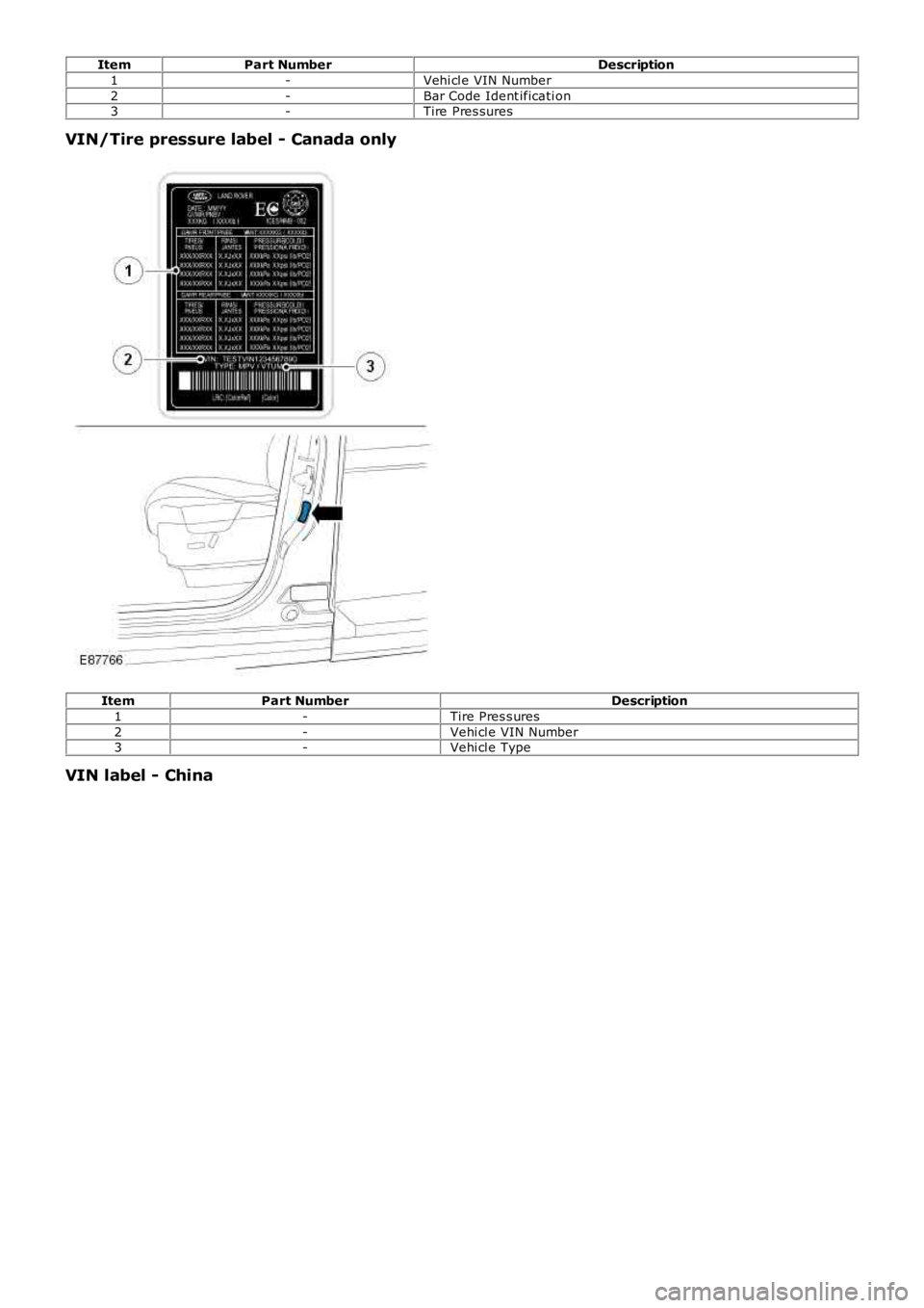
ItemPart NumberDescription
1-Vehi cl e VIN Number
2-Bar Code Ident ificati on3-Tire Pres sures
VIN/Tire pressure label - Canada only
ItemPart NumberDescription
1-Tire Pres s ures
2-Vehi cl e VIN Number3-Vehi cl e Type
VIN label - China
Page 272 of 3229
Publi s hed: 11-May-2011
Wheels and Tires -
Wheel Type
• CAUTIO NS:
CAUTIO N: W it h reduced s ize s pare wheel fit ted, do not exceed 50 mph (80 km/h) and repl ace wi th s tandard s izewheel at earlies t opportuni ty.
CAUTIO N: Do not use power t ool s when operat ing t he s pare wheel winch, rais e and l ower winch manual ly us i ng handt ool s only.
ItemSpecification
All oy6.5J x 16
All oy7.5J x 17All oy8.0J x 18
St eel7.0 J X 17
All oy wheel (Acces s ory)8.5J x 19St eel wheel (Spaces aver)4.0J x 17
Tire Sizes - Standard Fit
CAUTION: CAUTION: Inner tubes mus t not be fi tt ed wi th any of t hes e ti res .
Wheel SizeT ire SizeLoad index & Speed Rating6.5J x 16215/75 R16103H or 107H
7.5J x 17235/65 R17104V or 108V
7.0J X 17235/65 R17103H8.0J x 18235/60 R18103V OR 107V
4.0J x 17135/90 R17
Tire Sizes - Accessory Fit
CAUTION: CAUTION: Inner tubes mus t not be fi tt ed wi th any of t hes e ti res .
Wheel SizeT ire sizeSpeed Rating
8.0J x 19235/55 R19105V
Tire Pressures
Loading conditionbarlb/in²All conditions - Vehicle loaded to maximum vehicle gross w eight:
Front2.232
Rear2.232Spaces aver s pare wheel2.232
St andard si ze s pare wheel2.232
19" Acces sory wheel2.435
Recommended Lubricant
ItemLand Rover Part No.W heel hub s pigotRY L 105020
Torque Specifications
DescriptionNmlb-ft
Road wheel nut s *13398Tire l ow pres s ure s ens or86
* Road wheel nuts must be tightened by diagonal selection
Page 409 of 3229
Publi s hed: 11-May-2011
Brake System - General Information - Brake System
Diagnosi s and Tes ti ng
Principle of Operation
For a detail ed descripti on of the brake s ys t em, refer t o t he rel evant Des cript ion and Operat ion secti on in the workshopmanual. REFER to:
Brake Syst em (206-00 Brake Sys t em - General Informat ion, Des cript ion and Operat ion),Front Dis c Brake (206-03 Front Di sc Brake, Des cri pt ion and Operati on),Rear Di sc Brake (206-04 Rear Di s c Brake, Des cri pti on and Operati on),Parking Brake (206-05 Parki ng Brake and Actuat ion, Descri pti on and Operat ion),Hydraul ic Brake Act uati on (206-06 Hydraul ic Brake Act uati on, Des cript ion and Operat ion),Brake Boost er (206-07 Power Brake Act uat ion, Des cript ion and Operat ion).
Inspection and Verification
1. Verify t he cus t omer concern.1.
2. Vis ually ins pect for obvious s igns of damage and s ys t em i ntegri ty.2.
Visual Inspection
MechanicalElectricalBrake mast er cyl inderBrake cali per pi st on(s )Brake di scsW heel bearingsBrake padsPower brake boos t erVacuum pumpBrake pedal li nkageBrake boos ter vacuum hos eTires
Damaged or corroded wiring harnes sBrake mas ter cyli nder fluid level s wi tch
3. If an obvious cause for an obs erved or report ed concern is found, correct t he caus e (if pos s ible) beforeproceeding t o t he next s t ep.3.
4. If t he caus e is not vis ually evi dent , verify t he concern and refer t o t he Sympt om Chart.4.
Road Test
Carry out a road tes t to compare act ual vehicl e braking performance wi th the performance s t andards expected by t hedri ver. The abi li ty of t he t est driver to make val id compari s ons and det ect performance defi cienci es wil l depend onexperience.
The dri ver s hould have a t horough knowl edge of brake s ys t em operat ion and accept ed general performance guideli nes tomake good comparis ons and detect performance concerns .
An experienced brake t echnician will al ways es t abl is h a route that wi ll be us ed for all brake di agnos is road t es t s . Theroads s elected will be reasonably s moot h and level. Gravel or bumpy roads are not sui table because the s urface does notall ow t he ti res t o grip t he road equall y. Crowned roads s houl d be avoided becaus e of t he large amount of wei ght s hifted tot he low set of wheels on t his type of road. Once the route is es tabl is hed and cons ist ent ly us ed, the road s urface vari ablecan be eli minat ed from t he t es t resul ts .
Before a road tes t, obt ain a compl et e des cript ion of t he cus t omer concerns or s uspected condit ion. From t he des cript ion,t he techni cian's experience wi ll all ow t he techni cian t o mat ch pos s ibl e caus es wi th s ympt oms. Certai n components wil l bet agged as pos si ble s us pect s whil e others wil l be eli minated by the evidence. More i mport ant ly, t he cus t omer des cri pt ioncan reveal uns afe condit ions which s hould be checked or correct ed before the road t est . The descri pti on wil l als o help formt he bas i c approach t o t he road tes t by narrowi ng t he concern t o s peci fi c components , vehicle s peed or condit ions .
Begin t he road tes t wit h a general brake performance check. Keepi ng t he des cri pti on of the concern in mind, t est t hebrakes at different vehicle s peeds usi ng both light and heavy pedal pres s ure.
If the concern becomes evident duri ng thi s check, verify it fit s t he descri pti on given before the road t est . If t he concern isnot evi dent , att empt to dupl icate t he condi ti on us ing t he informat ion from the des cri pt ion.
If a concern exi st s , refer t o t he Symptom Chart.
Symptom Chart
SymptomPossible CauseAction
Brakes nois yBrake padsBrake dis csGO t o Pinpoint Test A.
Vibrati on when brakes areappliedW heels /t ires out of bal anceW heel hub nut s loos eBrake cal iper mounti ng bolt s loos eBrake padsForeign mat eri al /s crat ches /corrosi onon brake dis c contact surfacesExcess i ve brake dis c t hicknes s
GO t o Pinpoint Test B.
Page 632 of 3229
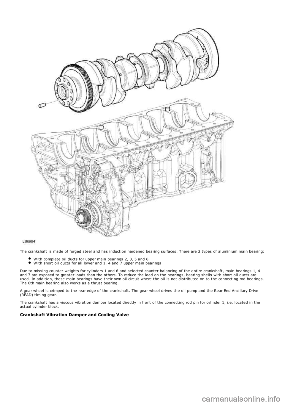
The crankshaft is made of forged s teel and has induction hardened bearing s urfaces . There are 2 types of aluminium main bearing:
W it h complet e oil duct s for upper main bearings 2, 3, 5 and 6W it h short oil ducts for all lower and 1, 4 and 7 upper main bearings
Due t o mis s ing count er-weight s for cylinders 1 and 6 and s elected count er-balancing of the entire crankshaft , main bearings 1, 4and 7 are exposed t o great er loads t han the ot hers. To reduce t he load on the bearings , bearing shells wit h s hort oil duct s areus ed. In addit ion, these main bearings have t heir own oil circuit where t he oil is not dis tribut ed on t o t he connecting rod bearings.The 6t h main bearing als o works as a t hrus t bearing.
A gear wheel is crimped to t he rear edge of the crankshaft . The gear wheel drives t he oil pump and the Rear End Ancillary Drive(READ) t iming gear.
The crankshaft has a vis cous vibration damper locat ed directly in front of t he connecting rod pin for cylinder 1, i.e. located in theact ual cylinder block.
Crankshaft Vibration Damper and Cooling Valve
Page 3104 of 3229
USING THIS PUBLICATION
08/20089
Section numbering
The sections in this publication are ordered to match the Global Outline numbering system as found in the current Workshop
Manual. The Power and Ground distribution circuits can be found under section 414-01, BATTERY, MOUNTING AND CABLES.
Note: Where circuit diagrams show more than one sub-system, the circuit will be located in the section that carries the first-named
sub-system, for example: Starting and Charging will be located under section 303-06 Starting System, since 'Starting' is the first-
named sub-system.
Circuit sheet numbering
The figures in brackets to the left of the page number indicate a circuit sheet number and the total number of sheets per circuit, for
example (01 / 05) represents sheet 1 of 5.
Understanding the circuit diagrams
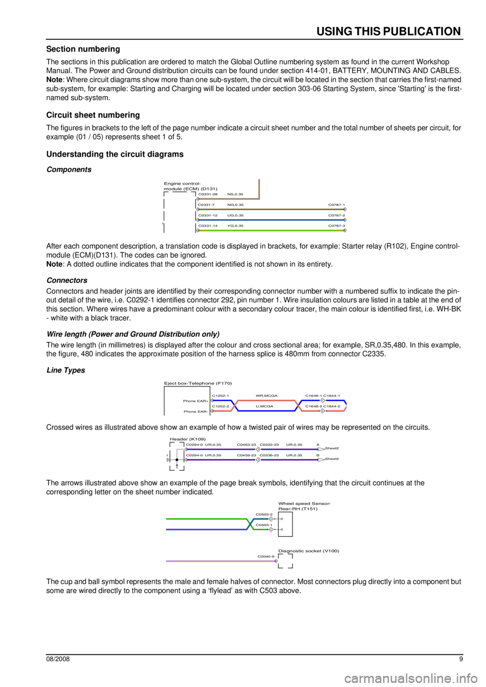
Components
After each component description, a translation code is displayed in brackets, for example: Starter relay (R102), Engine control-
module (ECM)(D131). The codes can be ignored.
Note: A dotted outline indicates that the component identified is not shown in its entirety.
Connectors
Connectors and header joints are identified by their corresponding connector number with a numbered suffix to indicate the pin-
out detail of the wire, i.e. C0292-1 identifies connector 292, pin number 1. Wire insulation colours are listed in a table at the end of
this section. Where wires have a predominant colour with a secondary colour tracer, the main colour is identified first, i.e. WH-BK
- white with a black tracer.
Wire length (Power and Ground Distribution only)
The wire length (in millimetres) is displayed after the colour and cross sectional area; for example, SR,0.35,480. In this example,
the figure, 480 indicates the approximate position of the harness splice is 480mm from connector C2335.
Line Types
Crossed wires as illustrated above show an example of how a twisted pair of wires may be represented on the circuits.
The arrows illustrated above show an example of the page break symbols, identifying that the circuit continues at the
corresponding letter on the sheet number indicated.
The cup and ball symbol represents the male and female halves of connector. Most connectors plug directly into a component but
some are wired directly to the component using a ‘flylead’ as with C503 above.
YG,0.35
UG,0.35
NG,0.35
NS,0.35module (ECM) (D131) Engine control-
C0331-14
C0331-12
C0331-7
C0331-28
C0787-2
C0787-3
C0787-1
U,MCGA
WR,MCGA
Eject box-Telephone (F170)
C1646-1 C1644-1
C1646-2 C1644-2C1252-2
Phone EAR-
C1252-1
Phone EAR+
UR,0.35UR,0.35
UR,0.35UR,0.35
B
Sheet2
A
Sheet2Header (K109)
C0336-23C0459-23
C0322-23C0463-23
C0294-00
C0294-0
Diagnostic socket (V100)
Rear-RH (T151) Wheel speed Sensor-
C0503-1
C0503-2
C0040-9
Page 3209 of 3229
USING THIS PUBLICATION
08/2008 9
Section numbering
The sections in this publication are ordered to match the Global Outline numbering system as found in the current Workshop
Manual. The Power and Ground distribution circuits can be found under section 414-01, BATTERY, MOUNTING AND CABLES.
Note : Where circuit diagrams show more than one sub-system, the circ uit will be located in the section that carries the first-named
sub-system, for example: Starting and Charging will be located unde r section 303-06 Starting System, since 'Starting' is the first-
named sub-system.
Circuit sheet numbering
The figures in brackets to the left of the page number indicate a circuit sheet number and the total number of sheets per circu it, for
example (01 / 05) represents sheet 1 of 5.
Understanding the circuit diagrams
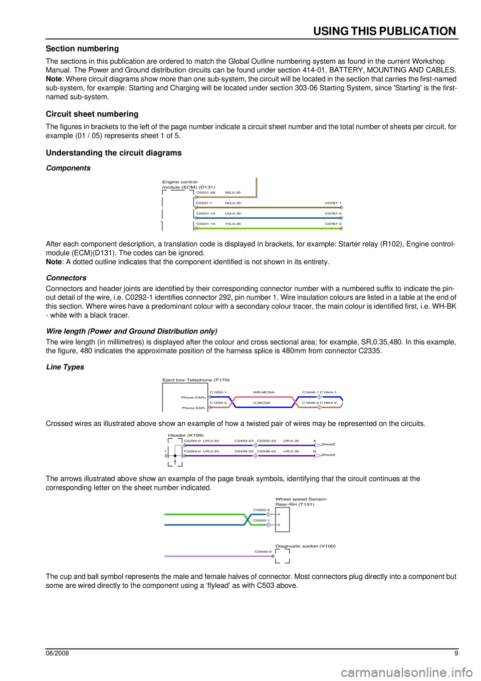
Components
After each component description, a translation code is displayed in brackets, for example: Starter relay (R102), Engine control-
module (ECM)(D131). The codes can be ignored.
Note : A dotted outline indicates that the compone nt identified is not shown in its entirety.
Connectors
Connectors and header joints are identified by their corresponding connector number wit h a numbered suffix to indicate the pin-
out detail of the wire, i.e. C0292-1 identifies connector 292, pin number 1. Wire insulation colours are listed in a table at t he end of
this section. Where wires have a predominan t colour with a secondary colour tracer, the main colour is identified first, i.e. WH-BK
- white with a black tracer.
Wire length (Power and Ground Distribution only)
The wire length (in millimetres) is displayed after the colour and cross sectional area; for example, SR,0.35,480. In this example,
the figure, 480 indicates the approximate position of the harness splice is 480mm from connector C2335.
Line Types
Crossed wires as illustrated above show an example of how a twisted pair of wires may be represented on the circuits.
The arrows illustrated above show an example of the page break symbols, identifying that the circuit continues at the
corresponding letter on the sheet number indicated.
The cup and ball symbol represents the male and female halves of connector. Most connectors plug directly into a component but
some are wired directly to the component using a ‘flylead’ as with C503 above.
YG,0.35
UG,0.35
NG,0.35
NS,0.35module (ECM) (D131)
Engine control-
C0331-14
C0331-12
C0331-7
C0331-28
C0787-2
C0787-3
C0787-1
U,MCGA
WR,MCGA
Eject box-Telephone (F170)
C1646-1 C1644-1
C1646-2 C1644-2C1252-2
Phone EAR-
C1252-1
Phone EAR+
UR,0.35UR,0.35
UR,0.35UR,0.35
B Sheet2
A
Sheet2Header (K109)
C0336-23C0459-23
C0322-23C0463-23
C0294-00
C0294-0
Diagnostic socket (V100)
Rear-RH (T151)
Wheel speed Sensor-
C0503-1
C0503-2
C0040-9