ECU LAND ROVER FRELANDER 2 2006 User Guide
[x] Cancel search | Manufacturer: LAND ROVER, Model Year: 2006, Model line: FRELANDER 2, Model: LAND ROVER FRELANDER 2 2006Pages: 3229, PDF Size: 78.5 MB
Page 96 of 3229
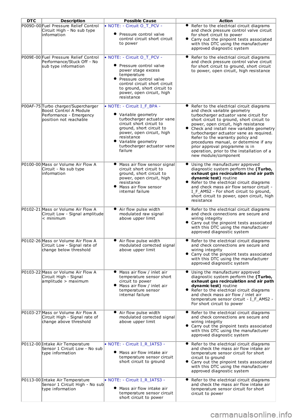
DT CDescriptionPossible CauseAction
P009D-00Fuel Pres s ure Rel ief ControlCircui t High - No s ub typeinformat ion
• NO TE: - Ci rcuit O_T_PCV -
Pres s ure control val vecontrol circui t s hort circuitt o power
Refer to the el ect ri cal circui t diagramsand check pres s ure control valve ci rcuitfor s hort circui t to powerCarry out t he pinpoint t est s as s oci at edwit h t his DTC us ing the manufact urerapproved di agnos ti c s ys t em
P009E-00Fuel Pres s ure Rel ief ControlPerformance/Stuck Off - Nos ub type i nformati on
• NO TE: - Ci rcuit O_T_PCV -
Pres s ure control val vepower s tage exces st emperaturePres s ure control val vecontrol circui t s hort circuitt o ground, s hort ci rcuit t opower, open circui t, highresi st ance
Refer to the el ect ri cal circui t diagramsand check pres s ure control valve ci rcuitfor s hort circui t to ground, s hort circui tto power, open ci rcuit , hi gh res i st ance
P00AF-75Turbo charger/SuperchargerBoost Cont rol A ModulePerformance - Emergencyposi ti on not reachable
• NO TE: - Ci rcuit I_F_BPA -
Vari able geometryt urbocharger actuat or vanecircui t s hort ci rcuit t oground, s hort circuit t opower, open circui t, highresi st anceVari able geometryt urbocharger actuat or vanefailure
Refer to the el ect ri cal circui t diagramsand check variabl e geomet ryturbocharger act uator vane ci rcuit forshort ci rcuit t o ground, s hort circuit t opower, open ci rcuit , high res i st anceCheck and i ns t all new vari abl e geometryturbocharger act uator vane as required.Refer to the warrant y policy andprocedures manual , or det ermi ne if anyprior approval programme is i noperati on, prior to the i nst all ati on of anew module/component
P0100-00Mas s or Vol ume Ai r Fl ow ACircui t - No s ub t ypeinformat ion
Mas s air flow sens or si gnalcircui t s hort ci rcuit t oground, s hort circuit t opower, open circui t, highresi st anceMas s air flow sens ori nt ernal fai lure
Usi ng t he manufacturer approveddiagnos t ic s yst em perform t he (T urbo,exhaust gas recirculation and air pathdynamic test) rout ineRefer to the el ect ri cal circui t diagramsand check mas s air flow sens or ci rcuit -I_F_AMS2 - For short ci rcuit t o ground,short ci rcuit t o power, open circui t, highres is t ance
P0102-21Mas s or Vol ume Ai r Fl ow ACircui t Low - Signal amplit ude< minimum
Ai r flow puls e wi dt hmodulat ed raw s ignalabove upper l imi t
Refer to the el ect ri cal circui t diagramsand check connecti ons are s ecure andwiring i ntegri tyCarry out t he pinpoint t est s as s oci at edwit h t his DTC us ing the manufact urerapproved di agnos ti c s ys t em
P0102-26Mas s or Vol ume Ai r Fl ow ACircui t Low - Signal rat e ofchange below threshold
Ai r flow puls e wi dt hmodulat ed correct ed si gnalabove upper l imi t
Refer to the el ect ri cal circui t diagramsand check connecti ons are s ecure andwiring i ntegri tyCarry out t he pinpoint t est s as s oci at edwit h t his DTC us ing the manufact urerapproved di agnos ti c s ys t em
P0103-22Mas s or Vol ume Ai r Fl ow ACircui t High - Si gnalampli tude > maximum
Mas s air flow / inlet ai rt emperature s ensor s hortcircui t to powerMas s air flow / inlet ai rt emperature s ensori nt ernal fai lure
Usi ng t he manufacturer approveddiagnos t ic s yst em perform t he (T urbo,exhaust gas recirculation and air pathdynamic test) rout ineRefer to the el ect ri cal circui t diagramsand check mas s air flow / inlet ai rtemperat ure sens or ci rcuit - I_F_AMS2 -For s hort circui t to power
P0103-27Mas s or Vol ume Ai r Fl ow ACircui t High - Si gnal rat e ofchange above threshold
Ai r flow puls e wi dt hmodulat ed correct ed si gnalabove upper l imi t
Refer to the el ect ri cal circui t diagramsand check connecti ons are s ecure andwiring i ntegri tyCarry out t he pinpoint t est s as s oci at edwit h t his DTC us ing the manufact urerapproved di agnos ti c s ys t em
P0112-00Int ake Air Temperat ureSens or 1 Ci rcuit Low - No s ubt ype i nformati on
• NO TE: - Ci rcuit I_R_IATS3 -
Mas s air flow int ake ai rt emperature s ensor circui ts hort circui t to ground
Refer to the el ect ri cal circui t diagramsand check t he mas s air flow i ntake airtemperat ure sens or ci rcuit for shortci rcuit t o groundCarry out t he pinpoint t est s as s oci at edwit h t his DTC us ing the manufact urerapproved di agnos ti c s ys t em
P0113-00Int ake Air Temperat ureSens or 1 Ci rcuit Hi gh - No s ubt ype i nformati on
• NO TE: - Ci rcuit I_R_IATS3 -
Mas s air flow int ake ai rt emperature s ensor circui ts hort circui t to power
Refer to the el ect ri cal circui t diagramsand check t he mas s air flow i ntake airtemperat ure sens or ci rcuit for shortci rcuit t o power
Page 105 of 3229
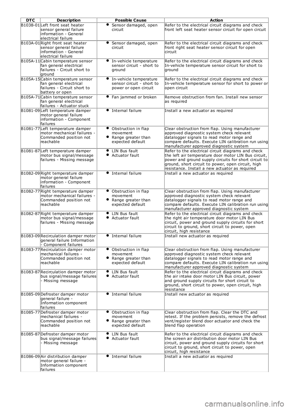
DT CDescriptionPossible CauseAction
B1038-01Left front s eat heaters ens or general fail ureinformat ion - Generalelectrical fail ure
Sens or damaged, opencircuitRefer t o t he electrical ci rcuit diagrams and checkfront left s eat heater s ensor circui t for open circuit
B103A-01Right front seat heaters ens or general fail ureinformat ion - Generalelectrical fail ure
Sens or damaged, opencircuitRefer t o t he electrical ci rcuit diagrams and checkfront ri ght seat heater s ens or circui t for opencircui t
B105A-11Cabi n t emperature s ensorfan general electricalfai lures - Ci rcuit s hort t oground
In-vehi cl e t emperatures ens or circuit - short toground
Refer t o t he electrical ci rcuit diagrams and checkIn-vehicle t emperat ure s ens or circui t for s hort t oground
B105A-15Cabi n t emperature s ensorfan general electricalfai lures - Ci rcuit s hort t obatt ery or open
In-vehi cl e t emperatures ens or circuit - short topower or open circui t
Refer t o t he electrical ci rcuit diagrams and checkIn-vehicle t emperat ure s ens or for short to power oropen circui t
B105A-71Cabi n t emperature s ensorfan general electricalfai lures - Act uat or s tuck
Fan jammed or brokenRemove obs truct ion from fan. Ins t all new s ensoras requi red
B1081-09Left t emperature dampermot or general fai lureinformat ion - Componentfai lures
Int ernal fai lureInst all a new act uat or as required
B1081-77Left t emperature dampermot or mechanical fail ures -Commanded pos i ti on notreachabl e
Obs truct ion i n flapmovementRange greater t hanexpected defaul t
Cl ear obs truct ion from fl ap. Usi ng manufacturerapproved diagnost ic s ys tem check rel evantdatal ogger s ignals t o read motor range andcompare defaul ts . Execut e LIN cal ibrat ion run us ingmanufact urer approved di agnos ti c s ys t emB1081-87Left t emperature dampermot or bus s ignal/mes s agefai lures - Mis s ing mes s age
LIN Bus faultAct uator faul tRefer t o t he electrical ci rcuit diagrams and checkt he left air t emperature door motor LIN Bus ci rcuit ,power and ground s uppl y circuit s for short ci rcuit t oground, s hort circuit t o power, open circui t, hi ghresi st ance. Inst all a new act uat or as required
B1082-09Right t emperature dampermot or general fai lureinformat ion - Componentfai lures
Int ernal fai lureInst all a new act uat or as required
B1082-77Right t emperature dampermot or mechanical fail ures -Commanded pos i ti on notreachabl e
Obs truct ion i n flapmovementRange greater t hanexpected defaul t
Cl ear obs truct ion from fl ap. Usi ng manufacturerapproved diagnost ic s ys tem check rel evantdatal ogger s ignals t o read motor range andcompare defaul ts . Execut e LIN cal ibrat ion run us ingmanufact urer approved di agnos ti c s ys t em
B1082-87Right t emperature dampermot or bus s ignal/mes s agefai lures - Mis s ing mes s age
LIN Bus faultAct uator faul tRefer t o t he electrical ci rcuit diagrams and checkt he ri ght ai r temperature door mot or LIN Buscircui t, power and ground s uppl y circuit s for shortcircui t to ground, s hort circui t t o power, opencircui t, hi gh res is t anceB1083-09Reci rculat ion damper motorgeneral fail ure Informati on- Component failures
Int ernal fai lureInst all new actuat or as required
B1083-77Reci rculat ion damper motormechani cal fai lures -Commanded pos i ti on notreachabl e
Obs truct ion i n flapmovementRange greater t hanexpected defaul t
Cl ear obs truct ion from fl ap. Usi ng manufacturerapproved diagnost ic s ys tem check rel evantdatal ogger s ignals t o read motor range andcompare defaul ts . Execut e LIN cal ibrat ion run us ingmanufact urer approved di agnos ti c s ys t em
B1083-87Reci rculat ion damper motorbus s ignal /mess age fai lures- Mis s ing mess age
LIN Bus faultAct uator faul tRefer t o t he electrical ci rcuit diagrams and checkt he air i nt ake door motor LIN Bus ci rcuit , powerand ground s upply circui ts for s hort circuit toground, s hort circuit t o power, open circui t, hi ghresi st anceB1085-09Defrost er damper mot orgeneral fail ure -Informat ion componentfai lures
Int ernal fai lureInst all new actuat or as required
B1085-77Defrost er damper mot ormechani cal fai lures -Commanded pos i ti on notreachabl e
Obs truct ion i n flapmovementRange greater t hanexpected defaul t
Cl ear obs truct ion from fl ap. Cl ear the DTC andretes t. If the problem pers is ts , remove the defros tvent/regis t er bl end door actuat or and check theblend flap operat ion
B1085-87Defrost er damper mot orbus s ignal /mess age fai lures- Mis s ing mess age
LIN Bus faultAct uator faul tRefer t o t he electrical ci rcuit diagrams and checkt he s creen air dis t ri but ion door mot or LIN Buscircui t, power and ground s uppl y circuit s for shortcircui t to ground, s hort circui t t o power, opencircui t, hi gh res is t ance
B1086-09Air dis t ri but ion dampermot or general fai lure -Informat ion componentfai lures
Int ernal fai lureInst all a new act uat or as required
Page 117 of 3229
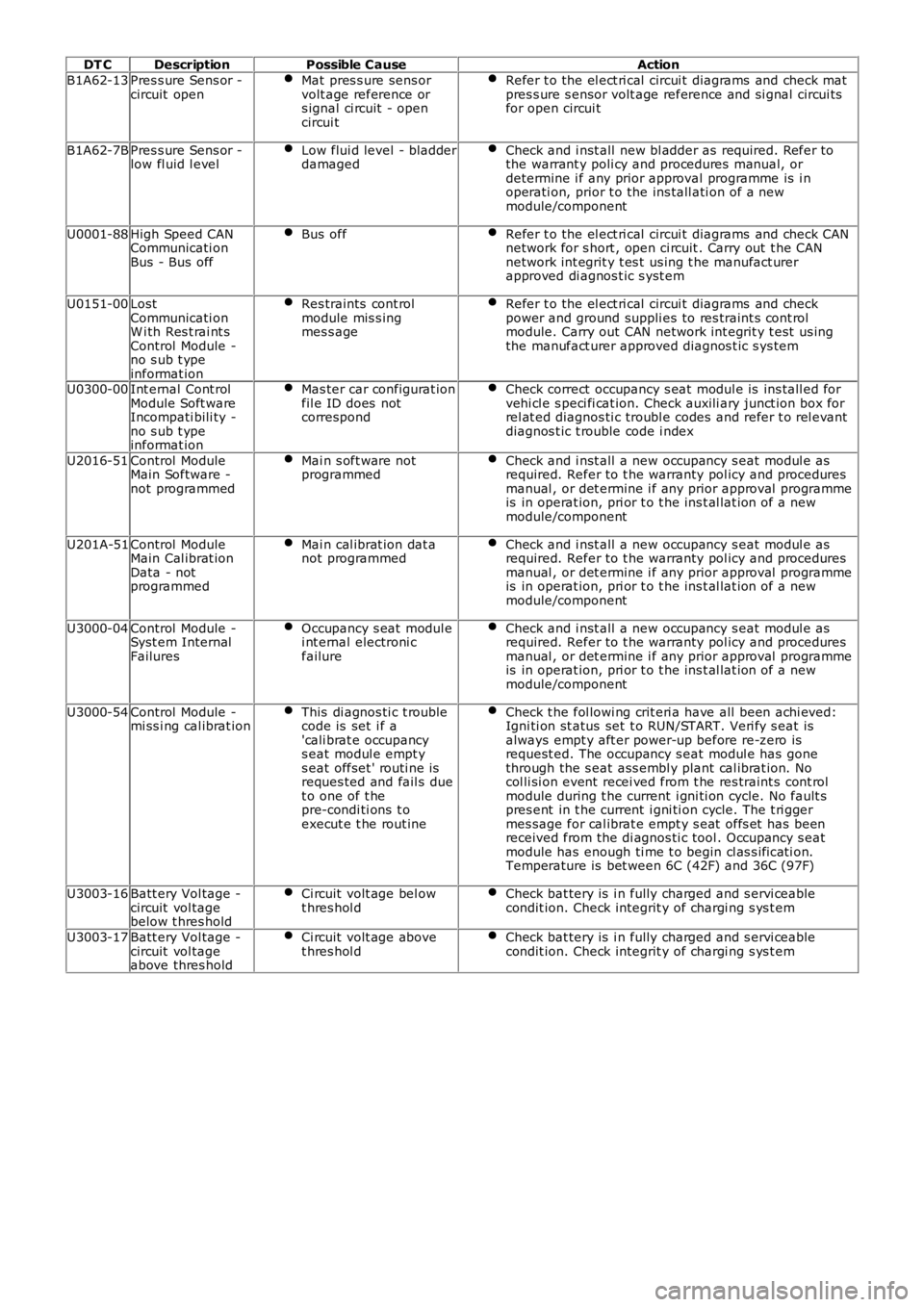
DT CDescriptionPossible CauseAction
B1A62-13Pres s ure Sens or -circuit openMat pres s ure sens orvolt age reference ors ignal ci rcuit - opencircui t
Refer t o the el ect ri cal circui t diagrams and check matpres s ure s ensor volt age reference and si gnal circui tsfor open circui t
B1A62-7BPres s ure Sens or -low fl uid l evelLow flui d level - bladderdamagedCheck and i nst all new bl adder as required. Refer tothe warrant y poli cy and procedures manual, ordetermine i f any prior approval programme is i noperati on, prior t o the ins tall ati on of a newmodule/component
U0001-88High Speed CANCommunicati onBus - Bus off
Bus offRefer t o the el ect ri cal circui t diagrams and check CANnetwork for s hort , open ci rcuit . Carry out t he CANnetwork int egrit y t es t us ing t he manufact urerapproved di agnos t ic s yst em
U0151-00LostCommunicati onW i th Res t rai nt sControl Module -no s ub t ypeinformat ion
Res traints cont rolmodule mis s ingmes s age
Refer t o the el ect ri cal circui t diagrams and checkpower and ground suppli es to res traint s cont rolmodule. Carry out CAN network int egrit y t est us ingthe manufact urer approved diagnos t ic s ys tem
U0300-00Int ernal Cont rolModule Soft wareIncompati bili ty -no s ub t ypeinformat ion
Mas ter car configurat ionfil e ID does notcorrespond
Check correct occupancy s eat modul e is ins tall ed forvehi cl e s peci fi cat ion. Check auxili ary junct ion box forrel at ed diagnos ti c troubl e codes and refer t o rel evantdiagnos t ic t rouble code i ndex
U2016-51Control ModuleMain Software -not programmed
Mai n s oft ware notprogrammedCheck and i nst all a new occupancy s eat modul e asrequired. Refer to t he warranty pol icy and proceduresmanual , or det ermine i f any prior approval programmeis in operat ion, pri or t o t he ins t al lat ion of a newmodule/component
U201A-51Control ModuleMain Cal ibrat ionData - notprogrammed
Mai n cal ibrat ion dat anot programmedCheck and i nst all a new occupancy s eat modul e asrequired. Refer to t he warranty pol icy and proceduresmanual , or det ermine i f any prior approval programmeis in operat ion, pri or t o t he ins t al lat ion of a newmodule/component
U3000-04Control Module -Syst em InternalFailures
Occupancy s eat modul ei nt ernal electroni cfailure
Check and i nst all a new occupancy s eat modul e asrequired. Refer to t he warranty pol icy and proceduresmanual , or det ermine i f any prior approval programmeis in operat ion, pri or t o t he ins t al lat ion of a newmodule/component
U3000-54Control Module -mi ss i ng cal ibrat ionThis di agnos ti c t roublecode is set i f a'cali brat e occupancys eat modul e empt ys eat offset ' routi ne isreques ted and fail s duet o one of t hepre-condi ti ons t oexecut e t he rout ine
Check t he fol lowi ng crit eri a have all been achi eved:Igni ti on st atus set t o RUN/START. Veri fy s eat isalways empt y aft er power-up before re-zero isrequest ed. The occupancy s eat modul e has gonethrough the s eat ass embl y plant cal ibrat ion. Nocol li si on event recei ved from t he res traint s cont rolmodule during t he current i gni ti on cycle. No fault spres ent in t he current i gni ti on cycle. The t ri ggermes sage for cal ibrat e empt y s eat offs et has beenreceived from the di agnos ti c tool . Occupancy s eatmodule has enough ti me t o begin cl as s ificati on.Temperature is bet ween 6C (42F) and 36C (97F)
U3003-16Batt ery Vol tage -circuit vol tagebelow t hres hold
Ci rcuit volt age bel owt hres hol dCheck bat tery is i n fully charged and s ervi ceablecondit ion. Check integrit y of chargi ng s ys t em
U3003-17Batt ery Vol tage -circuit vol tageabove thres hold
Ci rcuit volt age abovet hres hol dCheck bat tery is i n fully charged and s ervi ceablecondit ion. Check integrit y of chargi ng s ys t em
Page 163 of 3229
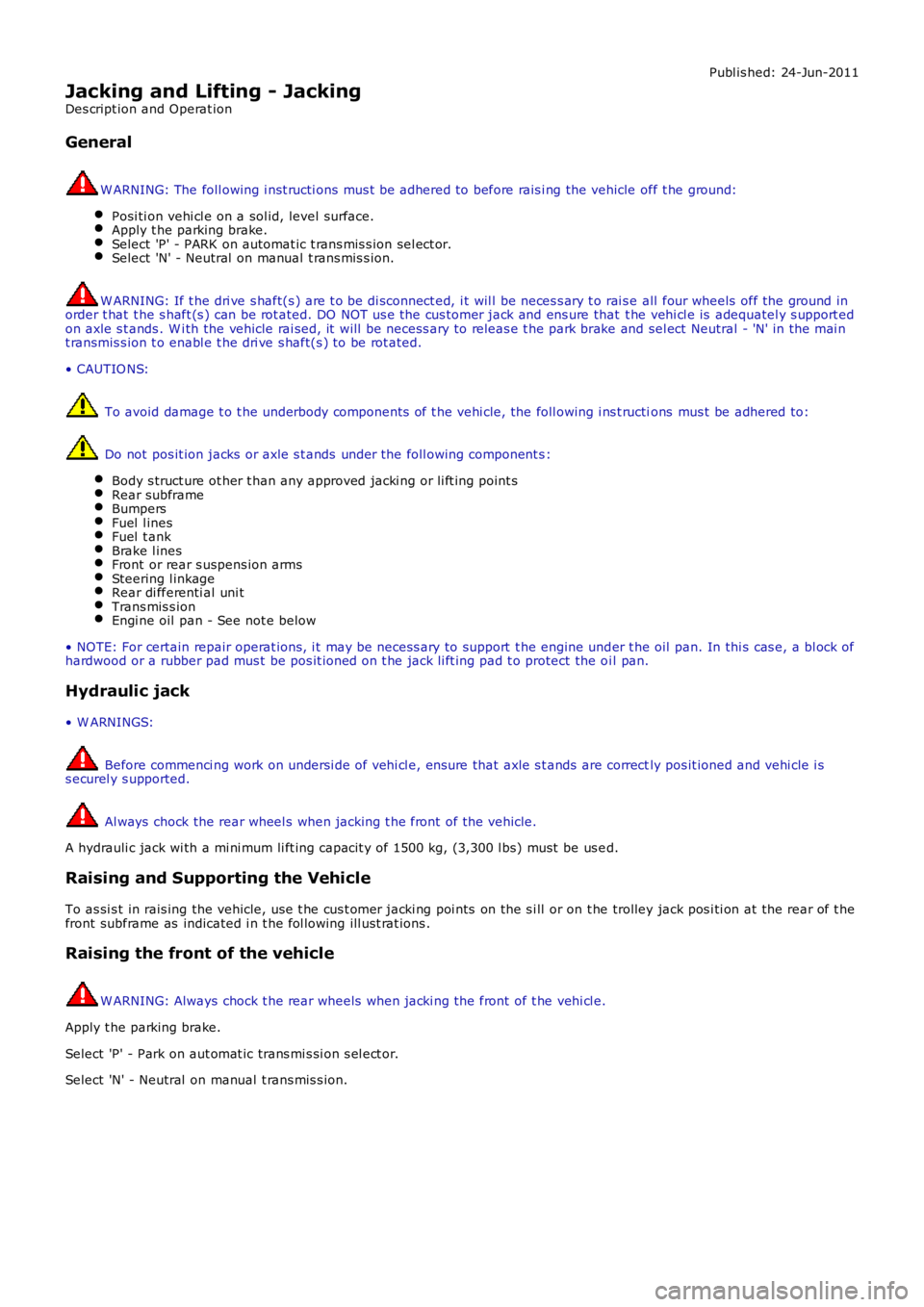
Publ is hed: 24-Jun-2011
Jacking and Lifting - Jacking
Des cript ion and Operat ion
General
W ARNING: The foll owing i nst ructi ons mus t be adhered to before rais i ng the vehicle off t he ground:
Posi ti on vehi cl e on a sol id, level surface.Apply t he parking brake.Select 'P' - PARK on automat ic t rans mis s ion sel ect or.Select 'N' - Neutral on manual t rans mis s ion.
W ARNING: If t he dri ve s haft(s ) are t o be di sconnect ed, i t wil l be neces s ary t o rai s e all four wheels off the ground inorder t hat t he s haft (s ) can be rot ated. DO NOT us e the cus tomer jack and ens ure that t he vehi cl e is adequatel y s upport edon axle s t ands . W i th the vehicle rai sed, it will be necess ary to releas e t he park brake and sel ect Neutral - 'N' in the mai nt ransmis s ion t o enabl e t he dri ve s haft(s ) to be rot ated.
• CAUTIO NS:
To avoid damage t o t he underbody components of t he vehi cle, the foll owing i ns t ructions mus t be adhered to:
Do not pos it ion jacks or axle s t ands under the foll owing component s :
Body s truct ure ot her t han any approved jacki ng or li ft ing point sRear subframeBumpersFuel l inesFuel t ankBrake l inesFront or rear s uspens ion armsSteering l inkageRear di fferenti al uni tTrans mis s ionEngi ne oil pan - See not e below
• NOTE: For certain repair operat ions, i t may be necess ary to support t he engine under t he oil pan. In thi s cas e, a bl ock ofhardwood or a rubber pad mus t be pos it ioned on t he jack li ft ing pad t o protect the oi l pan.
Hydraulic jack
• W ARNINGS:
Before commenci ng work on undersi de of vehi cl e, ens ure that axle s t ands are correctly pos it ioned and vehi cle i ss ecurel y s upported.
Al ways chock the rear wheel s when jacking t he front of the vehicle.
A hydrauli c jack wi th a mi ni mum li ft ing capacit y of 1500 kg, (3,300 l bs) must be us ed.
Raising and Supporting the Vehicle
To as si s t in rais ing the vehicle, us e t he cus t omer jacki ng poi nts on the s i ll or on t he trolley jack pos i ti on at the rear of t hefront subframe as indicated i n t he fol lowing ill ust rat ions .
Raising the front of the vehicle
W ARNING: Always chock t he rear wheels when jacki ng the front of t he vehi cl e.
Apply t he parking brake.
Select 'P' - Park on aut omat ic trans mi s si on s el ect or.
Select 'N' - Neutral on manual t rans mis s ion.
Page 164 of 3229
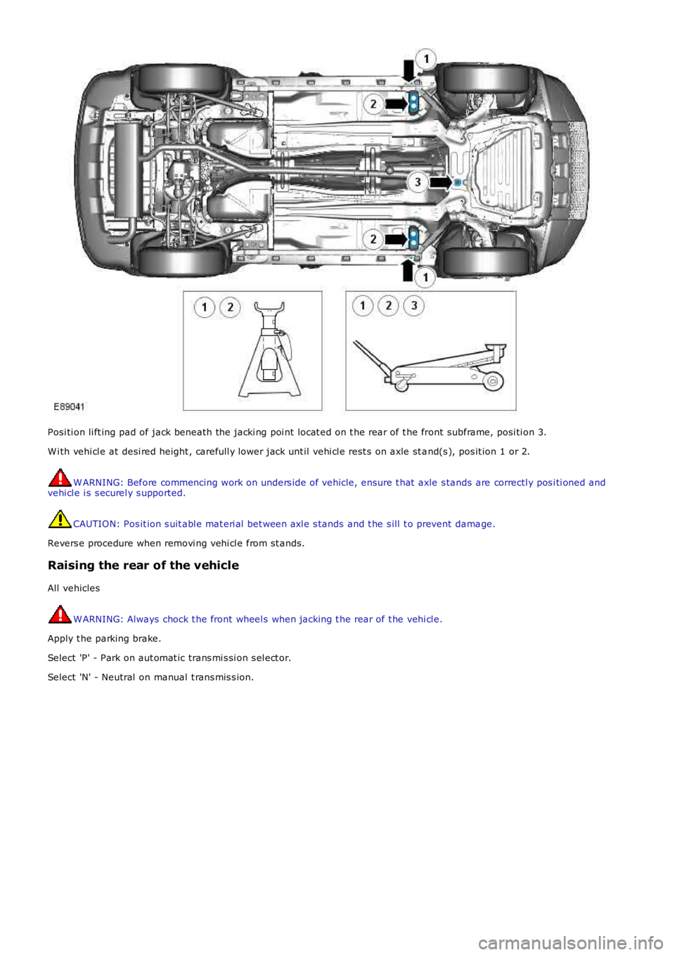
Posi ti on li ft ing pad of jack beneath the jacki ng poi nt locat ed on t he rear of t he front subframe, posi ti on 3.
W i th vehi cl e at desi red height , carefull y lower jack unt il vehi cl e rest s on axle st and(s ), pos it ion 1 or 2.
W ARNING: Before commencing work on unders ide of vehicle, ensure t hat axle s tands are correctl y pos i ti oned andvehi cl e i s s ecurel y s upported.
CAUTION: Pos it ion s uit abl e mat eri al bet ween axl e s tands and t he s ill t o prevent damage.
Revers e procedure when removi ng vehi cl e from st ands.
Raising the rear of the vehicle
All vehicles
W ARNING: Always chock t he front wheel s when jacking t he rear of t he vehi cl e.
Apply t he parking brake.
Select 'P' - Park on aut omat ic trans mi s si on s el ect or.
Select 'N' - Neutral on manual t rans mis s ion.
Page 165 of 3229
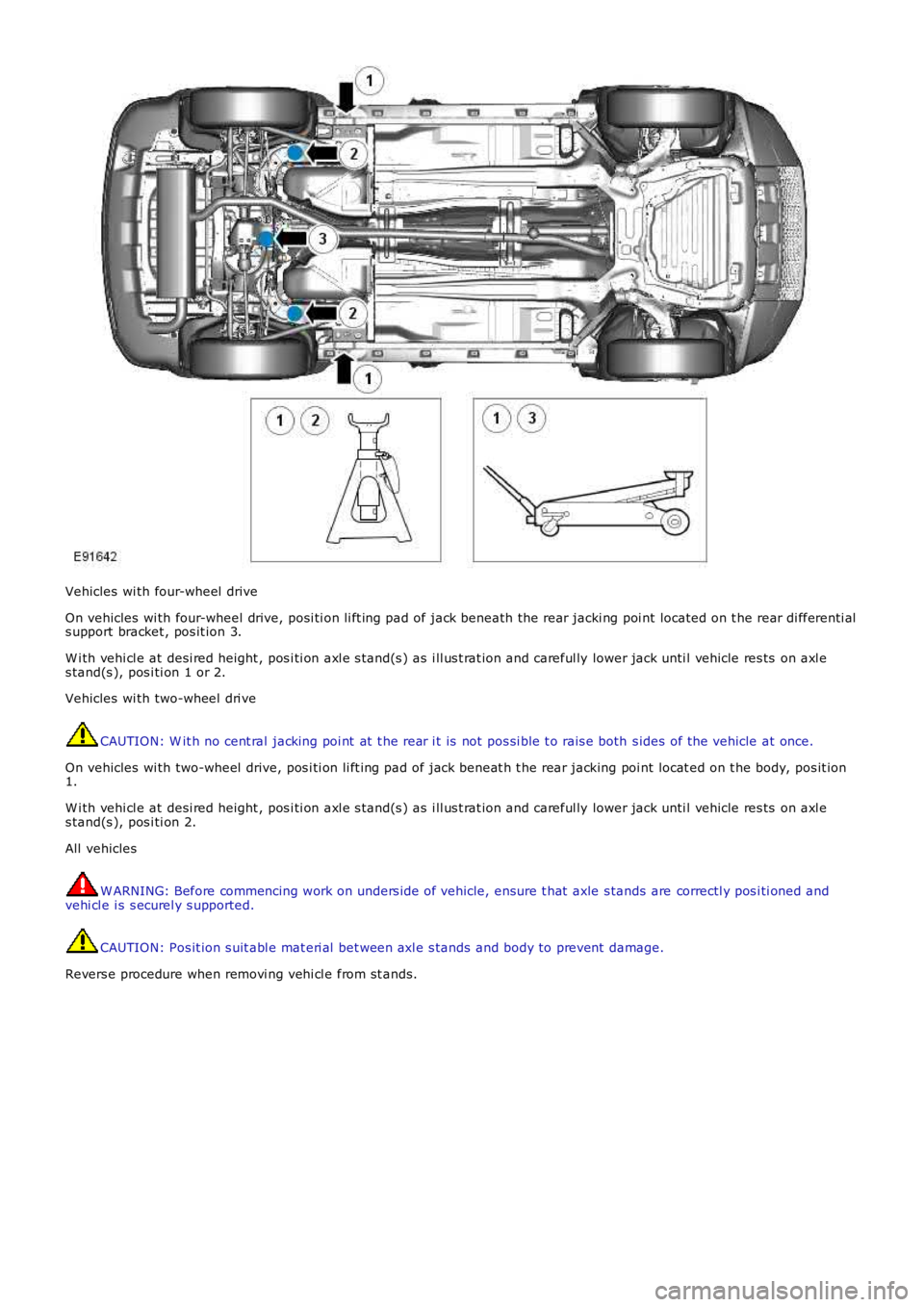
Vehicles wi th four-wheel drive
On vehicles wi th four-wheel drive, posi ti on li ft ing pad of jack beneath the rear jacki ng poi nt located on t he rear di fferenti als upport bracket , pos it ion 3.
W i th vehi cl e at desi red height , pos i ti on axl e s tand(s ) as i ll us t rat ion and careful ly lower jack unti l vehicle res ts on axl es tand(s ), pos i ti on 1 or 2.
Vehicles wi th two-wheel dri ve
CAUTION: W it h no cent ral jacking poi nt at t he rear i t is not pos si ble t o rais e both s ides of the vehicle at once.
On vehicles wi th two-wheel drive, pos i ti on li ft ing pad of jack beneat h t he rear jacking poi nt locat ed on t he body, pos it ion1.
W i th vehi cl e at desi red height , pos i ti on axl e s tand(s ) as i ll us t rat ion and careful ly lower jack unti l vehicle res ts on axl es tand(s ), pos i ti on 2.
All vehicles
W ARNING: Before commencing work on unders ide of vehicle, ensure t hat axle s tands are correctl y pos i ti oned andvehi cl e i s s ecurel y s upported.
CAUTION: Pos it ion s uit abl e mat eri al bet ween axl e s tands and body to prevent damage.
Revers e procedure when removi ng vehi cl e from st ands.
Page 169 of 3229
Publi s hed: 11-May-2011
Jacking and Lifting - Vehicle Recovery
Des cript ion and Operat ion
Towing Points
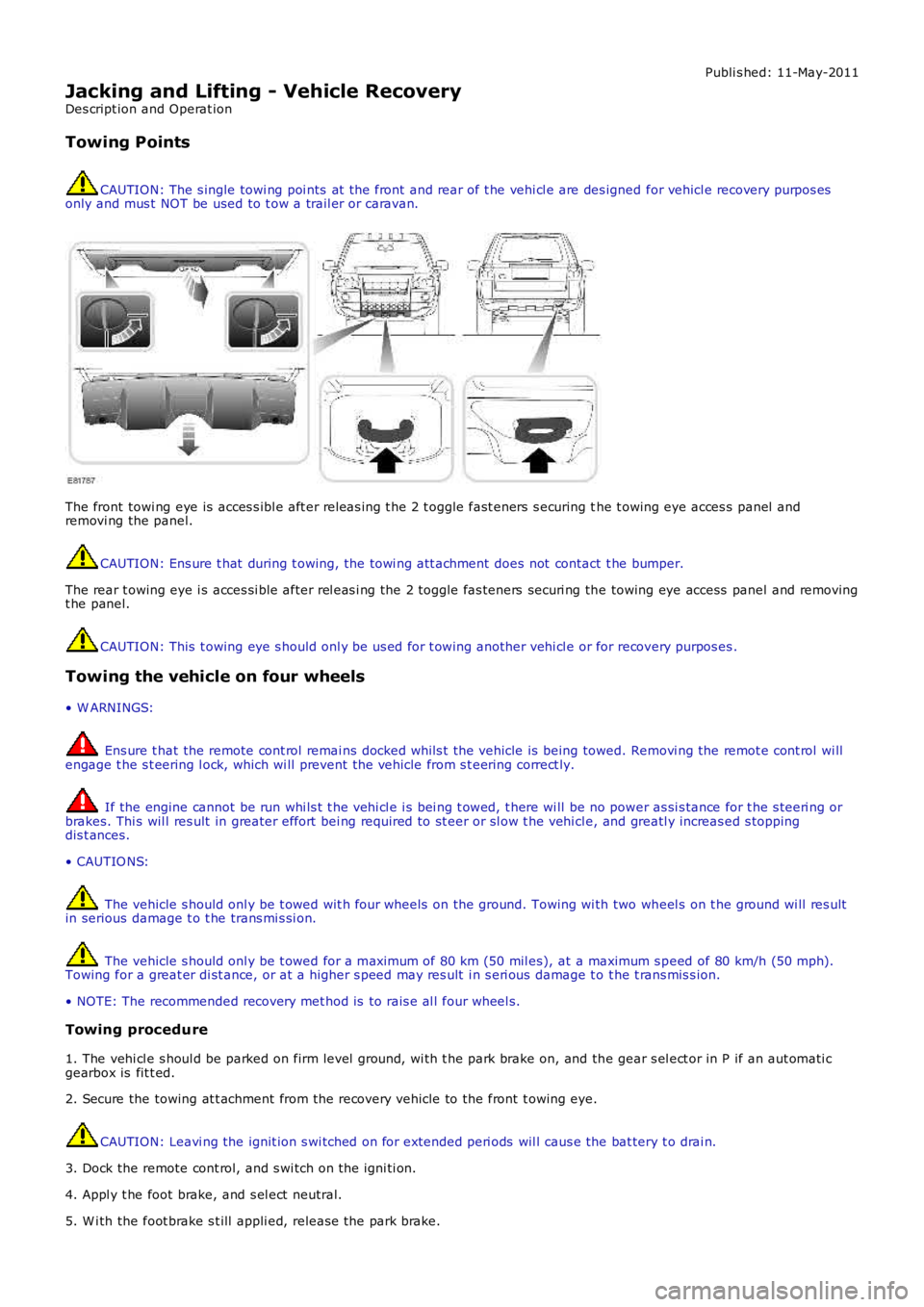
CAUTION: The s ingle towi ng poi nts at t he front and rear of t he vehi cl e are des igned for vehicl e recovery purpos esonly and mus t NOT be used to t ow a trail er or caravan.
The front towi ng eye is acces s ibl e aft er releas ing t he 2 t oggle fast eners s ecuring the t owing eye acces s panel andremovi ng the panel.
CAUTION: Ens ure t hat during t owing, the towi ng att achment does not contact t he bumper.
The rear t owing eye i s acces si ble after rel eas i ng the 2 toggle fas teners securi ng the towing eye access panel and removingt he panel.
CAUTION: This t owing eye s hould onl y be us ed for t owing another vehi cl e or for recovery purpos es .
Towing the vehicle on four wheels
• W ARNINGS:
Ens ure t hat the remote cont rol remai ns docked whil s t the vehicle is being towed. Removi ng the remot e cont rol wi llengage t he s t eering l ock, which wi ll prevent the vehicle from s t eering correct ly.
If the engine cannot be run whi ls t t he vehi cl e i s bei ng t owed, t here wi ll be no power as si s tance for t he s teeri ng orbrakes. Thi s wil l res ult in greater effort bei ng required to st eer or sl ow t he vehi cl e, and greatl y increas ed s toppingdis t ances.
• CAUTIO NS:
The vehicle s hould onl y be t owed wit h four wheels on the ground. Towing wi th two wheel s on t he ground wi ll res ultin serious damage t o t he trans mi s si on.
The vehicle s hould onl y be t owed for a maxi mum of 80 km (50 mil es), at a maximum s peed of 80 km/h (50 mph).Towing for a great er di st ance, or at a higher s peed may res ult i n s eri ous damage t o t he t rans mis s ion.
• NOTE: The recommended recovery met hod is to rais e al l four wheel s.
Towing procedure
1. The vehi cl e s houl d be parked on firm level ground, wi th t he park brake on, and the gear s el ect or in P if an aut omati cgearbox is fit t ed.
2. Secure the towing at t achment from the recovery vehicle to the front t owing eye.
CAUTION: Leavi ng the ignit ion s wi tched on for extended peri ods wil l caus e the bat tery t o drai n.
3. Dock the remote cont rol, and s wi tch on t he igni ti on.
4. Appl y t he foot brake, and s el ect neutral.
5. W i th the foot brake s t ill appli ed, releas e the park brake.
Page 170 of 3229
6. The vehi cl e can now be t owed a maxi mum of 80 km (50 mil es) at a maxi mum speed of 80 km/h (50 mph).
7. Upon arrival at t he des ti nat ion, ensure wherever pos s ibl e that t he vehi cl e i s par
ked on firm l evel ground.
8. Appl y t he park brake, and place t he s el ect or lever into the P pos i ti on.
9. Swit ch off t he ignit ion, and remove t he remote control. W ARNING: Use ext reme caut ion when det aching towing equi pment . Vehi cle movement is po
s s ible which can res ult i n
s erious i njuri es.
10. Remove the t owing at tachment from t he t owing eye.
Lashing Points
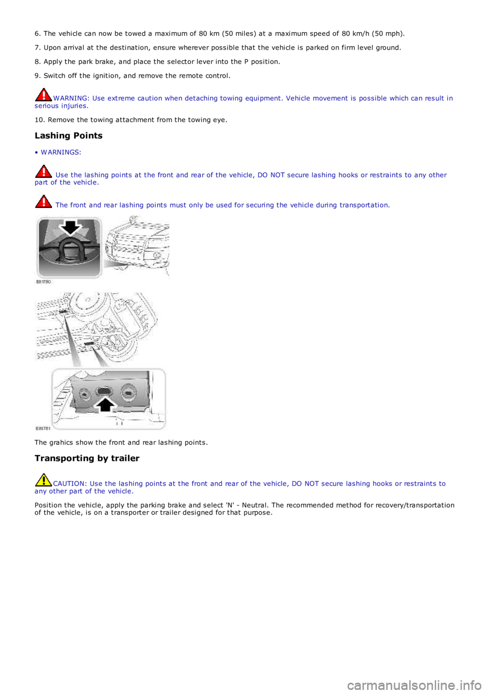
• W ARNINGS: Us e t he las hing poi nt s at t he front and rear of the vehicle, DO NOT s ecure las hing
hooks or res traint s to any other
part of t he vehi cl e. The front and rear l as hing poi nt s mus t only be used for s ecuri ng t he vehi cl e duri ng
trans port ati on.The grahics s how t he front and rear las hing point s .
Transporting by trailer CAUTION: Us e t he las hing point s at t he front and rear of the vehicle, DO NOT s ecure
las hing hooks or res traint s to
any other part of t he vehi cl e.
Posi ti on t he vehi cl e, apply the parki ng brake and s elect 'N' - Neutral. The recommen ded met hod for recovery/t rans portat ion
of the vehicle, i s on a t rans port er or t rai ler desi gned for t hat purpos e.
Page 172 of 3229
Check condit ion of batt ery.Check/top up bat tery electrolyte level .
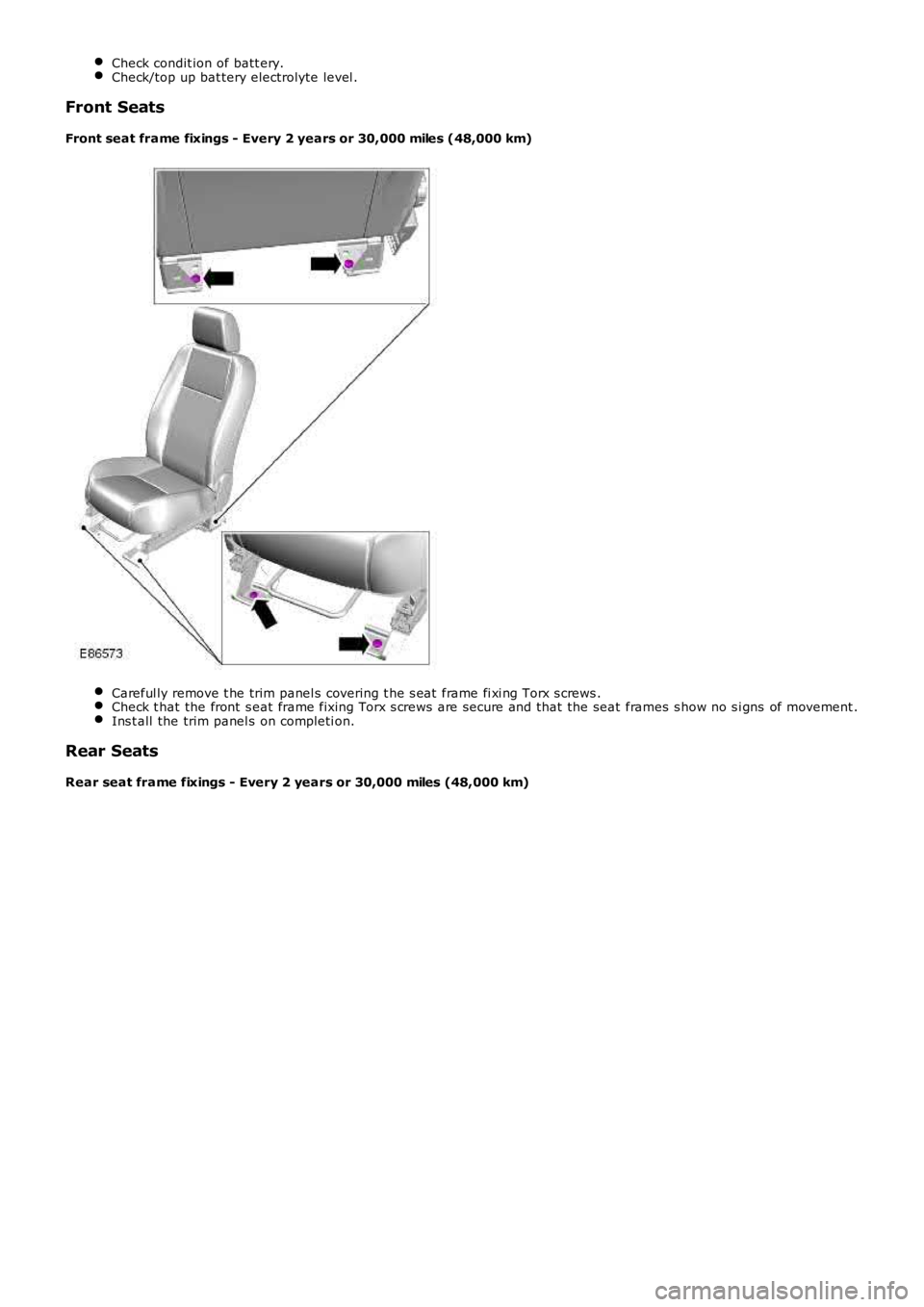
Front Seats
Front seat frame fixings - Every 2 years or 30,000 miles (48,000 km)
Careful ly remove t he trim panel s covering t he s eat frame fi xi ng Torx s crews .Check t hat the front s eat frame fixing Torx s crews are secure and that the seat frames s how no s i gns of movement .Ins t all the trim panel s on completi on.
Rear Seats
Rear seat frame fixings - Every 2 years or 30,000 miles (48,000 km)
Page 173 of 3229
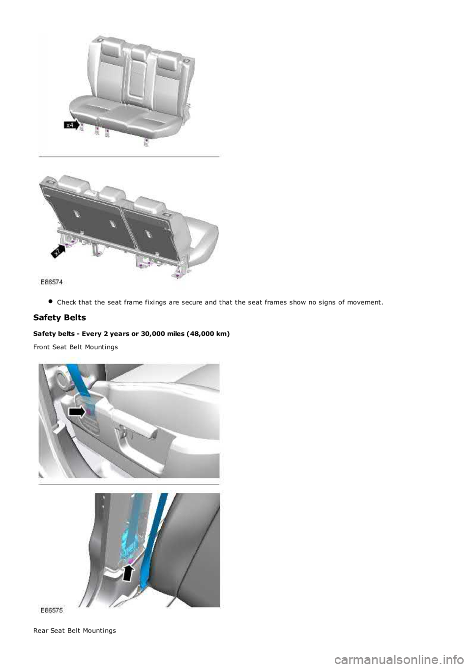
Check t hat the seat frame fixi ngs are s ecure and t hat t he s eat frames s how no s igns of movement .
Safety Belts
Safety belts - Every 2 years or 30,000 miles (48,000 km)
Front Seat Bel t Mount ings
Rear Seat Belt Mount ings