instrument panel LAND ROVER FRELANDER 2 2006 User Guide
[x] Cancel search | Manufacturer: LAND ROVER, Model Year: 2006, Model line: FRELANDER 2, Model: LAND ROVER FRELANDER 2 2006Pages: 3229, PDF Size: 78.5 MB
Page 2315 of 3229
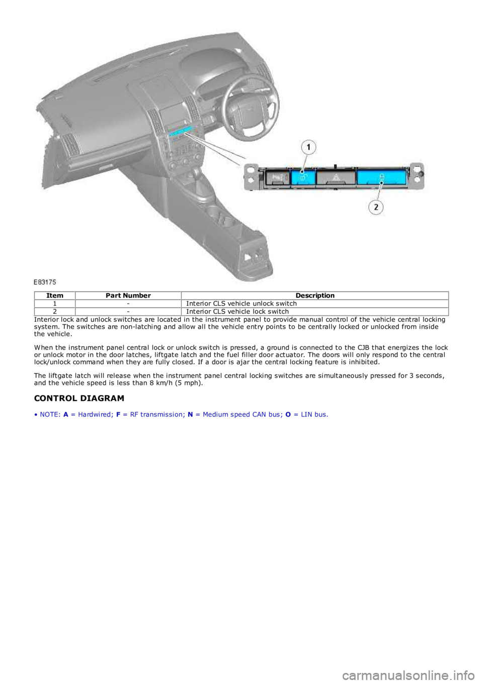
ItemPart NumberDescription1-Int eri or CLS vehi cle unl ock s witch2-Int eri or CLS vehi cle lock s wi tchInterior l ock and unl ock s witches are l ocated in the instrument panel to provide manual control of the vehicle cent ral lockingsystem. The s witches are non-l atchi ng and allow al l t he vehi cle ent ry points to be cent ral ly locked or unlocked from ins idethe vehicle.
W hen the i ns trument panel central lock or unlock swit ch is pres sed, a ground i s connected t o the CJB t hat energizes the lockor unlock mot or in the door latches, liftgat e l at ch and the fuel fil ler door act uator. The doors wil l only res pond to t he centrallock/unlock command when they are fully closed. If a door is ajar the cent ral locking feature is inhi bi ted.
The lift gate latch wi ll rel ease when the i ns trument panel central locki ng s wi tches are si mult aneous ly pres sed for 3 s econds ,and the vehicle speed is less than 8 km/h (5 mph).
CONTROL DIAGRAM
• NOTE: A = Hardwi red; F = RF transmis si on; N = Medium s peed CAN bus ; O = LIN bus.
Page 2317 of 3229
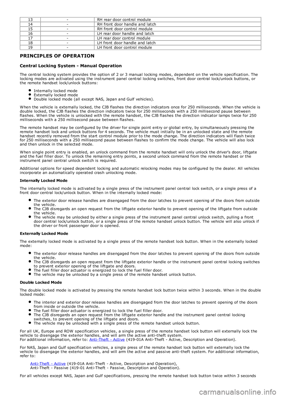
13-RH rear door cont rol module14-RH front door handl e and l at ch15-RH front door control module16-LH rear door handle and latch17-LH rear door cont rol modul e18-LH front door handle and l atch19-LH front door control module
PRINCIPLES OF OPERATION
Central Locking System - Manual Operation
The central locking s ys tem provides the option of 2 or 3 manual l ocking modes , dependent on the vehicle s pecificati on. Thelocki ng modes are acti vated usi ng t he inst rument panel cent ral locking switches, front door cent ral lock/unl ock but tons , orthe remote hands et lock/unlock butt ons:
Internall y l ocked modeExternal ly locked modeDouble l ocked mode (all except NAS, Japan and Gulf vehicles).
W hen the vehicle is externall y l ocked, the CJB flashes the di recti on indi cators once for 250 mi llis econds . W hen t he vehicle isdouble locked, t he CJB fl as hes the direct ion indicators t wi ce for 250 mil lis econds with a 250 mill isecond pause bet weenflashes . W hen t he vehicl e is unlocked with the remote hands et , t he CJB fl as hes the direction indicat or lamps twice for 250mi lli seconds wit h a 250 mi llis econd paus e between flashes.
The remote hands et may be confi gured by the dri ver for si ngle point ent ry or global ent ry, by s imultaneousl y press ing theremote hands et lock and unlock but tons for 4 s econds . The vehicle mus t i nit ially be i n an unlocked s tat e and the remotehandset recentl y removed from the start control module prior t o t he mode change. The di rection indi cat ors wil l flas h twicefor 250 mill iseconds with a 250 mill isecond pause bet ween flas hes to confirm the mode change. The vehi cle will also lockand then unlock in t he select ed mode.
W hen singl e point ent ry is enabled, an unl ock command from t he remot e handset wil l onl y unl ock the driver's door, l ift gateand the fuel fill er door. To unlock the remaining ent ry points , a s econd unlock command from the remote handset or theins trument panel central unlock swit ch is required.
Addi tional options for speed dependent locki ng and automat ic relocki ng modes may be configured by the deal er. All vehiclesincorporate an aut omatical ly operat ed cras h unlocki ng mode.
Internally Locked Mode
The int ernally locked mode is acti vated by a single pres s of the i ns trument panel central lock switch, or a s ingle pres s of afront door central lock/unlock butt on. W hen i n t he i nternal ly locked mode:
The exterior door releas e handles are di sengaged from the door lat ches t o prevent openi ng of the doors from outs idethe vehi cle.The CJB di sregards an open request from the l ift gate exterior handle to prevent opening of the lift gate from outsi dethe vehi cle.The vehi cle may be unlocked by eit her a s ingle press of the instrument panel cent ral unlock s wi tch, pulling a frontdoor central l ock/unlock butt on, or a s ingle press of t he remot e handset unl ock button. The vehicle wil l also unl ock i fthe driver or front pas senger door is opened.
Externally Locked Mode
The externally l ocked mode is act ivated by a si ngle pres s of the remote hands et lock butt on. W hen i n t he ext ernally lockedmode:
The exterior door releas e handles are di sengaged from the door lat ches t o prevent openi ng of the doors from outs idethe vehi cle.The CJB di sregards an open request from the l ift gate exterior handle or the inst rument panel cent ral locking s witchesto prevent exterior opening of the l ift gate and doors.The fuel fil ler door act uator i s energized t o l ock t he fuel filler door.The vehi cle may be unlocked by a s ingle press of the remote hands et unl ock but ton.
Double Locked Mode
The double locked mode is activat ed by pres sing the remote hands et lock butt on twice wi thin 3 seconds. W hen in the doublelocked mode:
The interior and ext erior door releas e handles are dis engaged from the door latches to prevent opening of the doorsfrom ins ide or out si de the vehi cle.The fuel fil ler door act uator i s energized t o l ock t he fuel filler door.The CJB di sregards an open request from the l ift gate exterior handle and the ins trument panel central lockingswit ches , t o prevent openi ng of t he li ftgat e and doors.The vehi cle may be unlocked with a s ingle pres s of the remote hands et unlock but ton.
For all UK, Europe and ROW s peci ficat ion vehicles , a s ingl e press of t he remot e handset l ock button wi ll externally lock t hevehicle to dis engage t he exterior handles, and wi ll arm the act ive ant i-t heft syst em.For addit ional informat ion, refer t o: Anti -Theft - Act ive (419-01A Anti-Theft - Act ive, Description and Operat ion).
For NAS, Japan and Gulf specifi cat ion vehicles, a singl e press of t he remot e handset lock button will externall y l ock t hevehicle to dis engage t he exterior handles, and wi ll arm the act ive and pas si ve anti -theft s ys tem. For additi onal informati on,refer to:
Ant i-Theft - Active (419-01A Anti -Theft - Active, Des cri pti on and Operation),Ant i-Theft - Pass ive (419-01 Ant i-Theft - Pass ive, Description and Operat ion).
For all vehi cles except NAS, Japan and Gul f s pecificati ons, pres si ng the remote hands et lock but ton t wi ce within 3 seconds
Page 2592 of 3229
Publis hed: 11-May-2011
Side Panel Sheet Metal Repairs - Side PanelRemoval and Installation
Removal
CAUTION: The side panel must be MIG slot brazed to its reinforcement, which contains DP600, (Dual Phase steel). MIG plug
w e lds / spot w e lds, must not be use d.
• NOTE: The side panel is serviced as a separate weld on panel, serviced less the fender mounting bracket, which is serviced
separately.
• NOTE: There are NVH elements attached inside this panel, they are not serviced on the new panel. If damaged, new element/s
will be required.
1. The s ide panel is replaced in conjunct ion wit h:
Front bumper cover
Front fender
Hood
Front door
Rear door
Quarter glass
Instrument panel
Windshield glass
Headliner
Rear bumper cover
2. For additional information relating to this repair procedure please
see the following:
Fo r a d d i t i o na l i nf o rma t i o n, re f e r t o : Body and Frame
(501-26 Body
Repairs - Vehicle Specific Information and Tolerance Checks,
Description and Operation) /
St a nd a rd W o rks ho p P ra ct i ce s
(100-00 General Informat ion,
Description and Operation).
3. Remove t he hood.
4. Remove the front fender.
5. Remove the front door.
Fo r a d d i t i o na l i nf o rma t i o n, re f e r t o : Front Door
(501-03 Body
Closures, Removal and Installation).
6. Remove t he rear door.
Fo r a d d i t i o na l i nf o rma t i o n, re f e r t o : Rear Door
(501-03 Body
Closures, Removal and Installation).
7. Remove the headliner.
Fo r a d d i t i o na l i nf o rma t i o n, re f e r t o : Headliner - Vehicles Without:
Tilting Roof Opening Panel (501-05 Int eri or Tri m and
Ornamentat ion, Removal and Inst all at ion) /
Headliner - Vehicles With: Tilting Roof Opening Panel
(501-05
Interior Trim and Ornamentation, Removal and Installation).
8. Re mo ve t he i ns t rume nt pa ne l .
Fo r a d d i t i o na l i nf o rma t i o n, re f e r t o : Inst rument Panel - TD4 2.2L
Di es e l (501-12 Inst rument Panel and Cons ole, Removal and
Installation).
9. Remove the windshield glass.
Fo r a d d i t i o na l i nf o rma t i o n, re f e r t o : Windshield Glass
(501-11
Glass, Frames and Mechanisms, Removal and Installation).
10. Remove the rear quarter glass.
Fo r a d d i t i o na l i nf o rma t i o n, re f e r t o : Rear Quarter Window Glass
(501-11 Glass, Frames and Mechanisms, Removal and Installation).
11. Re move t he re a r bumpe r co ve r.
Fo r a d d i t i o na l i nf o rma t i o n, re f e r t o : Rear Bumper Cover
(501-19
Bumpe rs , Re mo va l a nd I ns t a l l a t i o n).
12. Remove the upper and lower door hinges from the A-Pillar, 4 x
bolts.
13. Remove the upper and lower door hinges from the B-Pillar, 4 x
bolts.
14. Remove the front door striker from the B-Pillar.
15. Remove the rear door striker from the C-Pillar.
16. Remove the roof moulding, front and rear sect ions .
17. Re mo ve t he s i d e a i r curt a i n mo d ul e .
Fo r a d d i t i o na l i nf o rma t i o n, re f e r t o : Si d e A i r Curt a i n Mo d ul e
(501-20B Supplement al Res t raint Syst em, Removal and
Page 2593 of 3229
Installation).
18. Remove the front seat.
Fo r a d d i t i o na l i nf o rma t i o n, re f e r t o : Front Seat
(501-10 Seat ing,
Removal and Installation).
19. Remove the floor console.
Fo r a d d i t i o na l i nf o rma t i o n, re f e r t o : Fl oor Cons ol e
(501-12
Instrument Panel and Console, Removal and Installation).
20. Remove the RH & LH rocker panel inner trims.
21. Remove the rear seat cushion.
Fo r a d d i t i o na l i nf o rma t i o n, re f e r t o : Rear Seat Cushion
(501-10
Seating, Removal and Installation).
22. Re mo ve t he re a r ca rp e t s e ct i o n.
23. Remove the B-Pillar side impact sensor.
Fo r a d d i t i o na l i nf o rma t i o n, re f e r t o : B-Pillar Side Impact Sensor
(501-20B Supplement al Res t raint Syst em, Removal and
Installation).
24. Remove the front safety belt retractor.
Fo r a d d i t i o na l i nf o rma t i o n, re f e r t o : Front Safety Belt Retractor
(501-20A Safet y Belt Sys t em, Removal and Ins t al lat ion).
25. Remove the rear safety belt retractor.
Fo r a d d i t i o na l i nf o rma t i o n, re f e r t o : Rear Safety Belt Retractor
(501-20A Safet y Belt Sys t em, Removal and Ins t al lat ion).
26. Release and lay aside the front carpet section.
27. Re mo ve t he re a r ca rp e t s e ct i o n.
28. Remove the front wheel and tire. LINK
29. Remove the rear wheel and tire.
Fo r a d d i t i o na l i nf o rma t i o n, re f e r t o : Wheel and Tire
(204-04
Wheels and Tires, Removal and Installation).
30. Remove the rocker panel out er mouldi ng.
31. Remove the liftgate aperture weatherseal.
32. Remove the forced air extraction grille.
33. Release and lay aside the insulating material at the inner
bulkhead.
34. Release and lay aside the insulating material at the inner quarter
panel.
35. Release and lay aside the wiring harnesses at the A-Pillar,
B-Pillar and rocker panel.
36. Release and lay aside the wiring harness along the inner quarter
panel and back panel.
37. Release and lay aside the insulating material at the inner quarter
panel.
38. RH side: Drain the fuel tank.
Fo r a d d i t i o na l i nf o rma t i o n, re f e r t o : Fuel Tank Draining
(310-00
Fuel Sys t em - General Informat ion, General Procedures).
39. RH side: Remove the fuel tank filler pipe.
Fo r a d d i t i o na l i nf o rma t i o n, re f e r t o : Fuel Tank Filler Pipe
(310-01A
Fuel Tank and Lines - I6 3.2L Petrol, Removal and Installation).
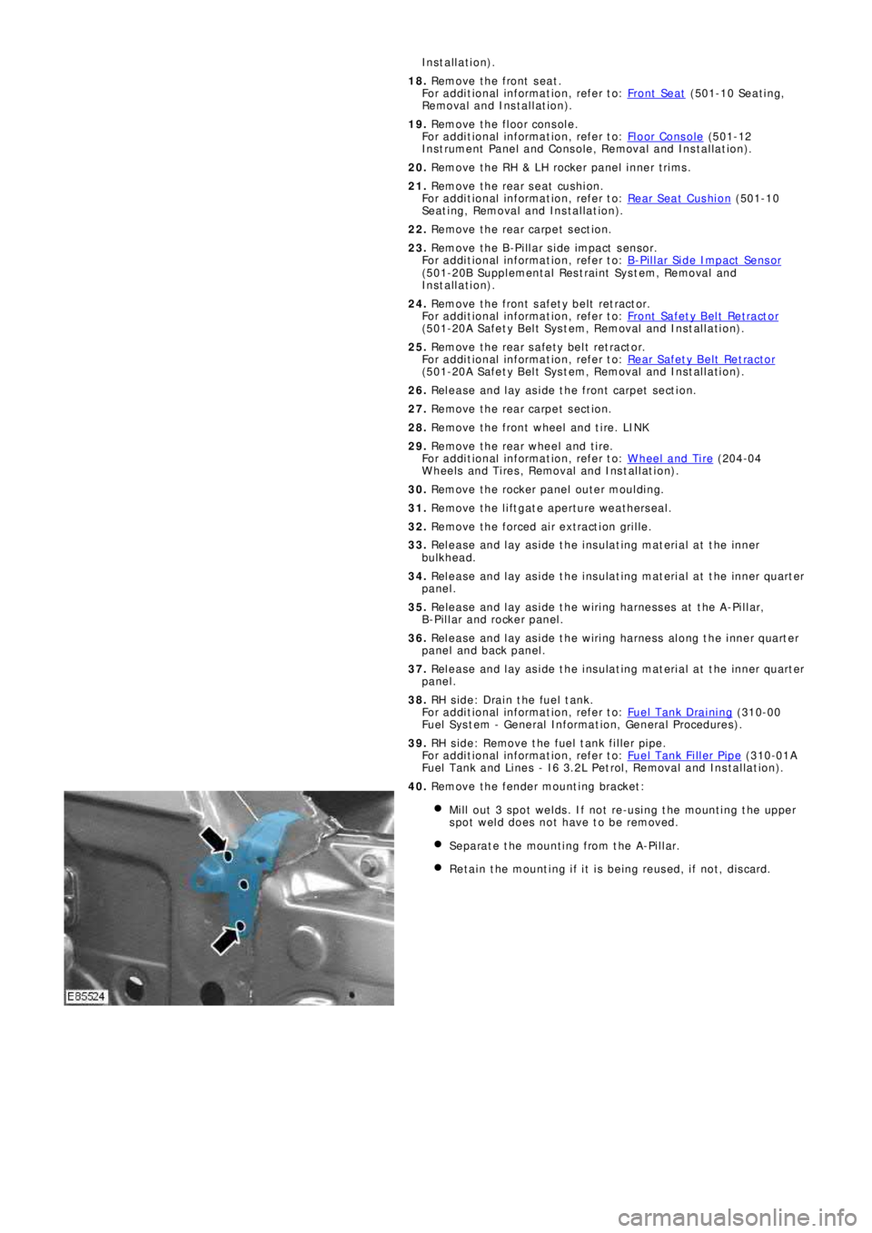
40. Remove the fender mounting bracket:
Mill out 3 spot welds. If not re-using the mounting the upper
spot weld does not have to be removed.
Separate the mounting from the A-Pillar.
Retain the mounting if it is being reused, if not, discard.
Page 2600 of 3229
Publ is hed: 11-May-2011
Side Panel Sheet Metal Repairs - Side Panel Front Section
Removal and Installation
Removal
CAUTION: The side panel front section must be MIG slot brazed to its reinforcement, which contains DP600, (Dual
Phase steel). MIG plug we lds / spot w elds, must not be use d.
• NOTE: The side panel front section is serviced as a separate weld on panel, serviced less the fender mounting bracket,
which is serviced separately.
• NOTE: There are NVH elements attached inside this panel, they are not serviced on the new panel. If damaged, new
element/s will be required.
1. The s ide panel front s ect ion is replaced in conjunct ion wit h:
Front bumper cover
Front fender
Hood
Front door
Rear door
Instrument panel
Windshield glass
Headliner
2. Fo r a d d i t i o na l i nf o rma t i o n re l a t i ng t o t hi s re p a i r p ro ce d ure
please see the following:
Fo r a d d i t i o na l i nf o rma t i o n, re f e r t o : Body and Frame
(501-26
Body Repairs - Vehicle Specific Information and Tolerance
Checks, Description and Operation) /
St a nd a rd W o rks ho p P ra ct i ce s
(100-00 Ge ne ra l I nf o rma t i o n,
Description and Operation).
3. Remove the hood.
4. Remove the front fender.
5. Remove the front door.
Fo r a d d i t i o na l i nf o rma t i o n, re f e r t o : Front Door
(501-03 Body
Closures, Removal and Installation).
6. Remove the rear door.
Fo r a d d i t i o na l i nf o rma t i o n, re f e r t o : Rear Door
(501-03 Body
Closures, Removal and Installation).
7. Remove the headliner.
Fo r a d d i t i o na l i nf o rma t i o n, re f e r t o : Headliner - Vehicles
Without: Tilting Roof Opening Panel (501-05 Int eri or Tri m and
Ornamentation, Removal and Installation) /
Headliner - Vehicles With: Tilting Roof Opening Panel
(501-05
Int erior Trim and Ornamentat ion, Removal and Installat ion).
8. Re move t he i ns t rume nt pa ne l .
Fo r a d d i t i o na l i nf o rma t i o n, re f e r t o : Instrument Panel - TD4
2.2L Di es el (501-12 Ins t rument Panel and Cons ole, Removal
and Installation).
9. Remove the windshield glass.
Fo r a d d i t i o na l i nf o rma t i o n, re f e r t o : Windshield Glass
(501-11
Glass, Frames and Mechanisms, Removal and Installation).
10. Remove the upper and lower door hinges from the A-Pillar, 4
x bol t s .
11. Remove the upper and lower door hinges from the B-Pillar, 4
x bol t s .
12. Remove the front door striker from the B-Pillar.
13. Re mo ve t he s i d e a i r curt a i n mo d ul e .
Fo r a d d i t i o na l i nf o rma t i o n, re f e r t o : Si d e A i r Curt a i n Mo d ul e
(501-20B Suppl ement al Res t rai nt Sys t em, Removal and
Installation).
14. Remove the rear seat cushion.
Fo r a d d i t i o na l i nf o rma t i o n, re f e r t o : Rear Seat Cushion
(501-10
Seating, Removal and Installation).
15. Remove the RH & LH rocker panel inner trims.
16. Remove the B-Pillar side impact sensor.
Fo r a d d i t i o na l i nf o rma t i o n, re f e r t o : B-Pillar Side Impact Sensor
Page 2607 of 3229
Publ is hed: 11-May-2011
Side Panel Sheet Metal Repairs - A-Pillar Outer Panel
Removal and Installation
Removal
CAUTION: The A-Pillar outer panel must be MIG slot brazed to the reinforcement, which is DP600, (Dual Phase steel).
MIG plug we lds / spot we lds, must not be used.
• NOTE: The A-Pillar outer panel is serviced as a separate weld-on panel. The fender mounting bracket is serviced
separately.
• NOTE: There are NVH elements attached inside this panel; they are not serviced on the new panel. If damaged, new
element(s) will be required.
1. The A-Pillar out er panel is replaced in conjunct ion wit h:
Front bumper cover
Hood
Front fender
Front door
Instrument panel
Windshield glass
Headliner
2. Fo r a d d i t i o na l i nf o rma t i o n re l a t i ng t o t hi s re p a i r p ro ce d ure
please see the following:
Fo r a d d i t i o na l i nf o rma t i o n, re f e r t o : Body and Frame
(501-26
Body Repairs - Vehicle Specific Information and Tolerance
Checks, Description and Operation) /
St a nd a rd W o rks ho p P ra ct i ce s
(100-00 Ge ne ra l I nf o rma t i o n,
Description and Operation).
3. Remove the hood.
4. Remove the front fender.
5. Remove the front door.
Fo r a d d i t i o na l i nf o rma t i o n, re f e r t o : Front Door
(501-03 Body
Closures, Removal and Installation).
6. Remove the headliner.
Fo r a d d i t i o na l i nf o rma t i o n, re f e r t o : Headliner - Vehicles
Without: Tilting Roof Opening Panel (501-05 Int eri or Tri m and
Ornamentation, Removal and Installation) /
Headliner - Vehicles With: Tilting Roof Opening Panel
(501-05
Int erior Trim and Ornamentat ion, Removal and Installat ion).
7. Re move t he i ns t rume nt pa ne l .
Fo r a d d i t i o na l i nf o rma t i o n, re f e r t o : Instrument Panel - TD4
2.2L Di es el (501-12 Ins t rument Panel and Cons ole, Removal
and Installation).
8. Remove the windshield glass.
Fo r a d d i t i o na l i nf o rma t i o n, re f e r t o : Windshield Glass
(501-11
Glass, Frames and Mechanisms, Removal and Installation).
9. Remove t he upper and l ower door hi nges from t he pi l lar, 4 x
bolts.
10. Re mo ve t he ro cke r p a ne l i nne r t ri m.
11. Re mo ve t he s i d e a i r curt a i n mo d ul e .
Fo r a d d i t i o na l i nf o rma t i o n, re f e r t o : Si d e A i r Curt a i n Mo d ul e
(501-20B Suppl ement al Res t rai nt Sys t em, Removal and
Installation).
12. Remove the front wheel and tire.
Fo r a d d i t i o na l i nf o rma t i o n, re f e r t o : Wheel and Tire
(204-04
Wheels and Tires, Removal and Installation).
13. Remove the rocker panel outer moulding.
14. Release and lay aside the front carpet section.
15. Re mo ve t he re a r ca rp e t s e ct i o n.
16. Remove the roof moulding, front and rear sections.
17. Release and lay aside the wiring harness along the A-Pillar
i nne r a nd i nne r ro cke r p a ne l .
18. Release and lay aside the insulating material at the inner
bulkhead.
Page 2613 of 3229
Publ is hed: 11-May-2011
Side Panel Sheet Metal Repairs - A-Pillar Reinforcement
Removal and Installation
Removal
• CAUTIONS:
The A-Pillar reinforcement is DP600, (Dual Phase steel) and must be MIG plug welded to the inner. Spot we lds must
not be used.
Ensure that all welded joints are suitably sealed and waterproofed, particularly in the areas where the original panel
adhesive / sealer cannot be replicated. W here necessary, seal the joints prior to the fitment of outer panels.
• NOTE: The A-Pillar reinforcement is unpicked from the side panel reinforcement 'ring-frame', it is not serviced separately.
• NOTE: There are NVH elements attached inside this panel, they are not serviced on the new panel. If damaged, new
element/s will be required.
1. The A-Pillar reinforcement is replaced in conjunction with:
Front bumper cover
Front fender
Front door
Instrument panel
Windshield glass
A-Pillar outer panel
2. Fo r a d d i t i o na l i nf o rma t i o n re l a t i ng t o t hi s re p a i r p ro ce d ure
please see the following:
Fo r a d d i t i o na l i nf o rma t i o n, re f e r t o : Body and Frame
(501-26
Body Repairs - Vehicle Specific Information and Tolerance
Checks, Description and Operation) /
St a nd a rd W o rks ho p P ra ct i ce s
(100-00 Ge ne ra l I nf o rma t i o n,
Description and Operation).
3. Remove the A-Pillar outer panel.
Fo r a d d i t i o na l i nf o rma t i o n, re f e r t o : A -P i l l a r O ut e r P a ne l
(501-29 Side Panel Sheet Metal Repairs, Removal and
Installation).
Page 2630 of 3229
Publ is hed: 11-May-2011
Side Panel Sheet Metal Repairs - Rocker Panel
Removal and Installation
Removal
CAUTION: The rocker panel must be MIG slot brazed to the rocker panel inner reinforcement, which is DP600, (Dual
Phase steel). MIG plug we lds / spot w elds must not be use d.
• N O T E: T he ro cke r p a ne l i s s e rvi ce d a s a s e p a ra t e w e l d -o n p a ne l .
1. The rocker pane l i s repl ace d i n conjunct i on wi t h:
Front bumper cover
Front fender
Front door
Rear door
2. Fo r a d d i t i o na l i nf o rma t i o n re l a t i ng t o t hi s re p a i r p ro ce d ure
please see the following:
Fo r a d d i t i o na l i nf o rma t i o n, re f e r t o : Body and Frame
(501-26
Body Repairs - Vehicle Specific Information and Tolerance
Checks, Description and Operation) /
St a nd a rd W o rks ho p P ra ct i ce s
(100-00 Ge ne ra l I nf o rma t i o n,
Description and Operation).
3. Remove the fender.
4. Remove the front door.
Fo r a d d i t i o na l i nf o rma t i o n, re f e r t o : Front Door
(501-03 Body
Closures, Removal and Installation).
5. Remove the rear door.
Fo r a d d i t i o na l i nf o rma t i o n, re f e r t o : Rear Door
(501-03 Body
Closures, Removal and Installation).
6. Remove the front road wheel.
Fo r a d d i t i o na l i nf o rma t i o n, re f e r t o : Wheel and Tire
(204-04
Wheels and Tires, Removal and Installation).
7. Re mo ve t he re a r ro a d w he e l .
Fo r a d d i t i o na l i nf o rma t i o n, re f e r t o : Wheel and Tire
(204-04
Wheels and Tires, Removal and Installation).
8. LH side: Remove the hood release handle.
9. Remove the front seat.
Fo r a d d i t i o na l i nf o rma t i o n, re f e r t o : Front Seat
(501-10
Seating, Removal and Installation).
10. Remove the floor console.
Fo r a d d i t i o na l i nf o rma t i o n, re f e r t o : Floor Console
(501-12
Instrument Panel and Console, Removal and Installation).
11. Remove the front door aperture weatherseal.
12. Remove the rear door aperture weatherseal.
13. Remove the cowl side trim panel.
Fo r a d d i t i o na l i nf o rma t i o n, re f e r t o : Cowl Side Trim Panel
(501-05 Int eri or Trim and Ornament at i on, Removal and
Installation).
14. Re mo ve t he B -P i l l a r up p e r t ri m.
Fo r a d d i t i o na l i nf o rma t i o n, re f e r t o : B-Pillar Upper Trim Panel
(501-05 Int eri or Trim and Ornament at i on, Removal and
Installation).
15. Remove the RH & LH B-Pillar lower trims.
Fo r a d d i t i o na l i nf o rma t i o n, re f e r t o : B-Pillar Lower Trim Panel
(501-05 Int eri or Trim and Ornament at i on, Removal and
Installation).
16. Remove the rear quarter trim panel.
Fo r a d d i t i o na l i nf o rma t i o n, re f e r t o : Rear Quarter Trim Panel
(501-05 Int eri or Trim and Ornament at i on, Removal and
Installation).
17. Remove the RH & LH rocker panel inner trims.
18. Remove the rocker panel outer moulding.
19. Remove the back panel inner trim.
20. Remove the rear seat cushion.
Fo r a d d i t i o na l i nf o rma t i o n, re f e r t o : Rear Seat Cushion
(501-10
Seating, Removal and Installation).
21. Remove the front safety belt retractor.
Page 2636 of 3229
Publ is hed: 11-May-2011
Rear End Sheet Metal Repairs - Quarter Panel
Removal and Installation
Removal
CAUTION: The quarter panel must be MIG slot brazed to the rocker panel inner reinforcement, which is DP600, (Dual
Phase steel). MIG plug we lds / spot w elds must not be use d in this are a.
• NOTE: The quarter panel is serviced as a separate weld-on panel.
• NOTE: There are NVH elements inside this panel, they are not serviced on the new panel. If damaged, a new element
will be required.
1. The quarter panel is replaced in conjunction with:
Rear bumper cover
Rear door
Quarter glass
Headliner
2. Fo r a d d i t i o na l i nf o rma t i o n re l a t i ng t o t hi s re p a i r p ro ce d ure
please see the following:
Fo r a d d i t i o na l i nf o rma t i o n, re f e r t o : Body and Frame
(501-26
Body Repairs - Vehicle Specific Information and Tolerance
Checks, Description and Operation) /
St a nd a rd W o rks ho p P ra ct i ce s
(100-00 Ge ne ra l I nf o rma t i o n,
Description and Operation).
3. Re move t he re a r bumpe r co ve r.
Fo r a d d i t i o na l i nf o rma t i o n, re f e r t o : Rear Bumper
(501-19
Bumpe rs , Re mo va l a nd Ins t a l l a t i on).
4. Remove the rear door.
Fo r a d d i t i o na l i nf o rma t i o n, re f e r t o : Rear Door
(501-03 Body
Closures, Removal and Installation).
5. Remove the headliner.
Fo r a d d i t i o na l i nf o rma t i o n, re f e r t o : Headliner - Vehicles
Without: Tilting Roof Opening Panel (501-05 Int eri or Tri m and
Ornamentation, Removal and Installation) /
Headliner - Vehicles With: Tilting Roof Opening Panel
(501-05
Int erior Trim and Ornamentat ion, Removal and Installat ion).
6. Re mo ve t he re a r d o o r s t ri ke r f ro m t he C-P i l l a r.
7. Remove the roof moulding, front and rear sections.
8. Re mo ve t he s i d e a i r curt a i n mo d ul e .
Fo r a d d i t i o na l i nf o rma t i o n, re f e r t o : Si d e A i r Curt a i n Mo d ul e
(501-20B Suppl ement al Res t rai nt Sys t em, Removal and
Installation).
9. Remove the rear quarter glass.
Fo r a d d i t i o na l i nf o rma t i o n, re f e r t o : Rear Quarter Window
Gl a s s (501-11 Glass, Frames and Mechanisms, Removal and
Installation).
10. Remove the front seat.
Fo r a d d i t i o na l i nf o rma t i o n, re f e r t o : Front Seat
(501-10
Seating, Removal and Installation).
11. Remove the floor console.
Fo r a d d i t i o na l i nf o rma t i o n, re f e r t o : Floor Console
(501-12
Instrument Panel and Console, Removal and Installation).
12. Remove the RH & LH rocker panel inner trims.
13. Remove the rear seat cushion.
Fo r a d d i t i o na l i nf o rma t i o n, re f e r t o : Rear Seat Cushion
(501-10
Seating, Removal and Installation).
14. Re mo ve t he re a r ca rp e t s e ct i o n.
15. Remove the rear safety belt retractor.
Fo r a d d i t i o na l i nf o rma t i o n, re f e r t o : Rear Safety Belt Retractor
(501-20A Safe t y Bel t Sys t em, Removal and Ins t al l at i on).
16. Remove the liftgate aperture weatherseal.
17. Remove the forced air extraction grille.
18. Remove the rear wheel and tire.
Fo r a d d i t i o na l i nf o rma t i o n, re f e r t o : Wheel and Tire
(204-04
Wheels and Tires, Removal and Installation).
19. Remove the rocker panel outer moulding.
20. Release and lay aside the wiring harness along the inner
Page 2723 of 3229

Contents
3
R
Quick start
QUICK START ................................................... 7
Filling station information
FILLING STATION INFORMATION................... 33
Introduction
SYMBOLS GLOSSARY .................................... 35
LABEL LOCATIONS ......................................... 35
HEALTH AND SAFETY ..................................... 36
DATA RECORDING.......................................... 37
DISABILITY MODIFICATIONS ......................... 37
PARTS AND ACCESSORIES ............................ 37
Keys and remote controls
USING THE KEY .............................................. 40
GENERAL INFORMATION ON RADIO
FREQUENCIES ................................................ 40
USING THE REMOTE CONTROL ..................... 41
Locks
LOCKING AND UNLOCKING ............................ 44
Alarm
ARMING THE ALARM ..................................... 45
DISARMING THE ALARM ............................... 46
Seats
SITTING IN THE CORRECT POSITION ............ 47
MANUAL SEATS ............................................. 48
ELECTRIC SEATS ............................................ 49
HEAD RESTRAINTS ........................................ 51
REAR SEATS................................................... 51
HEATED SEATS............................................... 53
Seat belts
PRINCIPLE OF OPERATION ............................ 54
SEAT BELT REMINDER ................................... 55
FASTENING THE SEAT BELTS ........................ 56
SEAT BELT HEIGHT ADJUSTMENT................. 56
USING SEAT BELTS DURI NG PREGNANCY .... 57
Supplementary restraints system
PRINCIPLE OF OPERATION ............................ 58
AIRBAG WARNING LAMP ............................... 61
DISABLING THE PASSENGER AIRBAG ........... 62
AIRBAG SERVICE INFORMATION ................... 63
Child safety
CHILD SEATS ................................................. 64
BOOSTER CUSHIONS ..................................... 66
ISOFIX ANCHOR POINTS................................ 67
CHILD SAFETY LOCKS ................................... 69
Steering wheel
ADJUSTING THE STEERING WHEEL .............. 70
AUDIO CONTROL ........................................... 70
Lighting
LIGHTING CONTROL ...................................... 72
FRONT FOG LAMPS........................................ 72
REAR FOG LAMPS.......................................... 73
ADJUSTING THE HEADLAMPS....................... 73
HEADLAMP LEVELLING ................................. 73
HAZARD WARNING FLASHERS...................... 74
ADAPTIVE FRONT LIGHTING SYSTEM (AFS) . 74
DIRECTION INDICATORS ............................... 75
INTERIOR LAMPS .......................................... 76
APPROACH LAMPS ........................................ 76
CHANGING A BULB ........................................ 77
BULB SPECIFICATION CHART ........................ 86
Wipers and washers
WINDSCREEN WIPERS .................................. 87
RAIN SENSOR ................................................ 87
WINDSCREEN WASHERS............................... 88
HEADLAMP WASHERS................................... 88
REAR WINDOW WIPER AND WASHERS ........ 89
ADJUSTING THE WINDSCREEN WASHER JETS .
89
CHECKING THE WIPER BLADES .................... 90
CHANGING THE WIPER BLADES.................... 90
Windows and mirrors
ELECTRIC WINDOWS ..................................... 93
EXTERIOR MIRRORS ..................................... 94
ELECTRIC EXTERIOR MIRRORS .................... 95
INTERIOR MIRROR ........................................ 96
Instruments
INSTRUMENT PANEL OVERVIEW .................. 97
Information displays
TRIP COMPUTER ........................................... 99
INFORMATION MESSAGES ............................ 99