instrument panel LAND ROVER FRELANDER 2 2006 Owner's Manual
[x] Cancel search | Manufacturer: LAND ROVER, Model Year: 2006, Model line: FRELANDER 2, Model: LAND ROVER FRELANDER 2 2006Pages: 3229, PDF Size: 78.5 MB
Page 2739 of 3229
19
Quick start
R
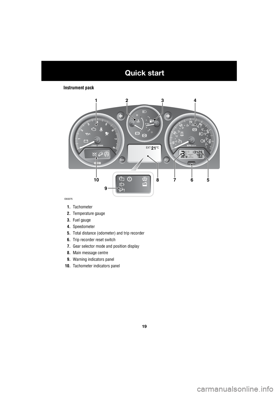
Instrument pack
1. Tachometer
2. Temperature gauge
3. Fuel gauge
4. Speedometer
5. Total distance (odometer) and trip recorder
6. Trip recorder reset switch
7. Gear selector mode and position display
8. Main message centre
9. Warning indicators panel
10. Tachometer indi cators panel
EXT C21
E83375
567108
9
1423
Page 2759 of 3229
39
Introduction
R
Airbag system
To prevent malfunction of the airbag system
always consult a Land Rover Dealer/
Authorised Repairer before fitting any of the
following:
• Electronic equipment such as a mobile
phone, two-way radio or in-car
entertainment system.
• Accessories attached to the front of the
vehicle.
• Any modification to the front of the vehicle.
• Any modification involving the removal or
repair of any wiring or component in the
vicinity of any of the airbag system
components, including the steering wheel,
steering column, instrument or facia
panels.
• Any modification to th e facia panels or
steering wheel.
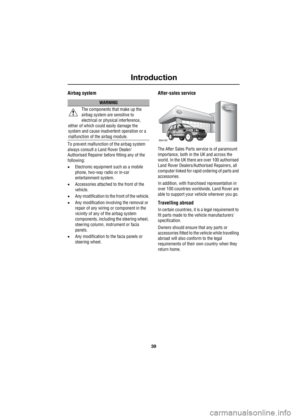
After-sales service
The After Sales Parts service is of paramount
importance, both in th e UK and across the
world. In the UK there are over 100 authorised
Land Rover Dealers/Authorised Repairers, all
computer linked for rapid ordering of parts and
accessories.
In addition, with franch ised representation in
over 100 countries worldwide, Land Rover are
able to support your vehicle wherever you go.
Travelling abroad
In certain countries, it is a legal requirement to
fit parts made to the vehicle manufacturers'
specification.
Owners should ensure that any parts or
accessories fitted to the vehicle while travelling
abroad will also conform to the legal
requirements of their own country when they
return home.
WARNING
The components that make up the
airbag system are sensitive to
electrical or physical interference,
either of which coul d easily damage the
system and cause inadvertent operation or a
malfunction of th e airbag module.
E84193
Page 2817 of 3229
97
Instruments
R
InstrumentsINSTRUMENT PANEL OVERVIEW
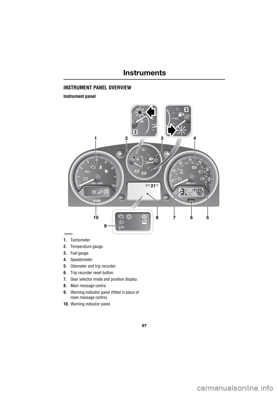
Instrument panel
1. Tachometer.
2. Temperature gauge.
3. Fuel gauge.
4. Speedometer.
5. Odometer and trip recorder.
6. Trip recorder reset button.
7. Gear selector mode and position display.
8. Main message centre.
9. Warning indicator panel (fitted in place of
main message centre).
10. Warning indicator panel.
EXT C21
E83004
567108
9
1423
2
3
Page 2818 of 3229
Instruments
98
L
Tachometer
Indicates engine spee d in revolutions per
minute (RPM) x 1000.
Temperature gauge
If the pointer moves onto the red line and the
red warning indicator illu minates severe engine
damage can occur.
If the engine overheats, stop the vehicle as
soon as safety pe rmits. Switch the engine off
and allow it to cool down. If the problem
reoccurs, seek qualified assistance before
continuing.
Note: If engine temperatur e rises to the point
where overheating may occur, there may be a
noticeable reduction in engine power, and the
air conditioning may cease operation. This is a
normal operating strate gy to reduce load on
the engine and assist with cooling.
Fuel gauge
Once the fuel level has dropped to the point
where the range is approximately 80 km (50
miles) the low fuel warning indicator will
illuminate.
As a reminder for the location of the fuel filler,
there is an arrow next to the fuel pump symbol
which points to the releva nt side of the vehicle.
Speedometer
Indicates road speed. Odometer
Indicates the total distance which the vehicle
has travelled.
Trip recorder
Indicates the distance travelled since the last
reset, and can be used to measure the distance
of individual journeys.
Trip recorder reset button
Resets the distance shown on the trip recorder
to zero.
Note: Once the trip recorder has been reset to
zero, the previously recorded distance will be
lost.
Gear selector mode and positiondisplay
Displays the currently selected gear on
vehicle's fitted with automatic transmission.
Main message centre
Displays warning, and information messages.
See INFORMATION MESSAGES (page 99).
Warning indicator panel (fitted in place of
main message centre)
If a main message centre is not fitted, the
warning indicator pane l will provide system
status information.
Warning indicator panel
The warning indicator panel will provide
system status information.
CAUTION
Serious engine damage can occur if the
vehicle is driven whilst the engine is
overheating.
CAUTION
Never allow the vehicle to run out of
fuel. The resulting mis-fire may cause
serious damage to the catalytic
convertor.
Page 2875 of 3229
155
Vehicle care
R
Underbody maintenance
Corrosive materials used on highways to
control snow and ice, as well as accumulations
from off-road driving or wading in salt water,
can collect on the vehi cle's underbody. If these
materials are not removed accelerated
corrosion can occur. Regularly flush the
underbody with plain wate r, and pay particular
attention to areas where mud and debris
collect.
If damage or corrosion are detected, have the
vehicle checked by a Land Rover
Dealer/Authorised Re pairer as soon as
possible.
Glass and mirrors
The rear screen, and mi rror glass' should only
be cleaned using soapy water and a soft cloth.
This will avoid damaging the reflective surface
of the mirror, and the heating elements and
antenna in the rear screen.
Never use abrasive cleaning products, or metal
ice scrapers on the mirrors or the front/rear
screens.
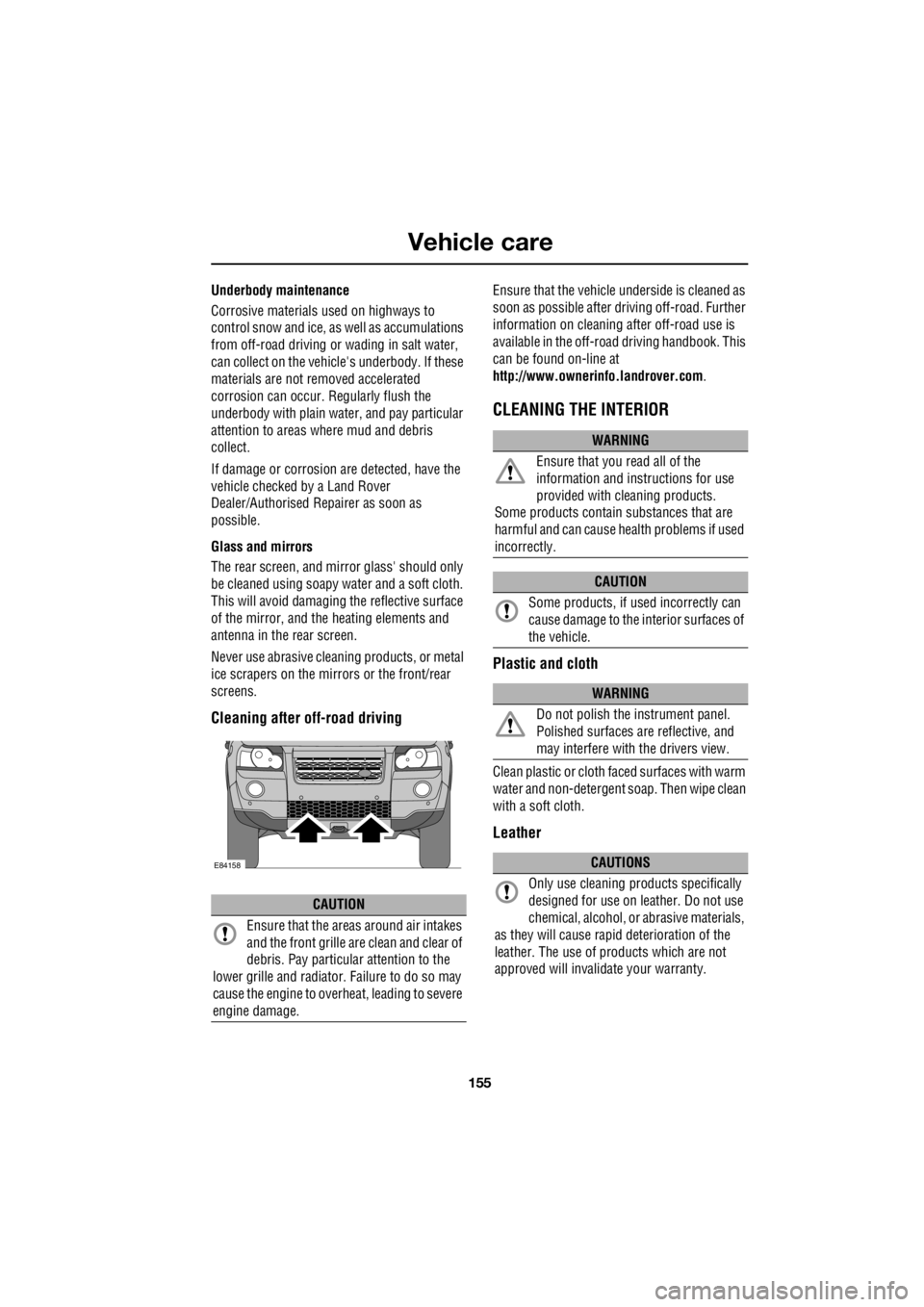
Cleaning after off-road driving
Ensure that the vehicle und erside is cleaned as
soon as possible after dr iving off-road. Further
information on cleaning af ter off-road use is
available in the off-road driving handbook. This
can be found on-line at
http://www.ownerinfo.landrover.com .
CLEANING THE INTERIOR
Plastic and cloth
Clean plastic or cloth faced surfaces with warm
water and non-detergent soap. Then wipe clean
with a soft cloth.
Leather
CAUTION
Ensure that the areas around air intakes
and the front grille ar e clean and clear of
debris. Pay particular attention to the
lower grille and radiator . Failure to do so may
cause the engine to overheat, leading to severe
engine damage.
E84158
WARNING
Ensure that you read all of the
information and inst ructions for use
provided with cleaning products.
Some products contain substances that are
harmful and can cause he alth problems if used
incorrectly.
CAUTION
Some products, if us ed incorrectly can
cause damage to the in terior surfaces of
the vehicle.
WARNING
Do not polish the instrument panel.
Polished surfaces are reflective, and
may interfere with the drivers view.
CAUTIONS
Only use cleaning pr oducts specifically
designed for use on le ather. Do not use
chemical, alcohol, or abrasive materials,
as they will cause rapi d deterioration of the
leather. The use of products which are not
approved will invalidate your warranty.
Page 2887 of 3229
167
Maintenance
R
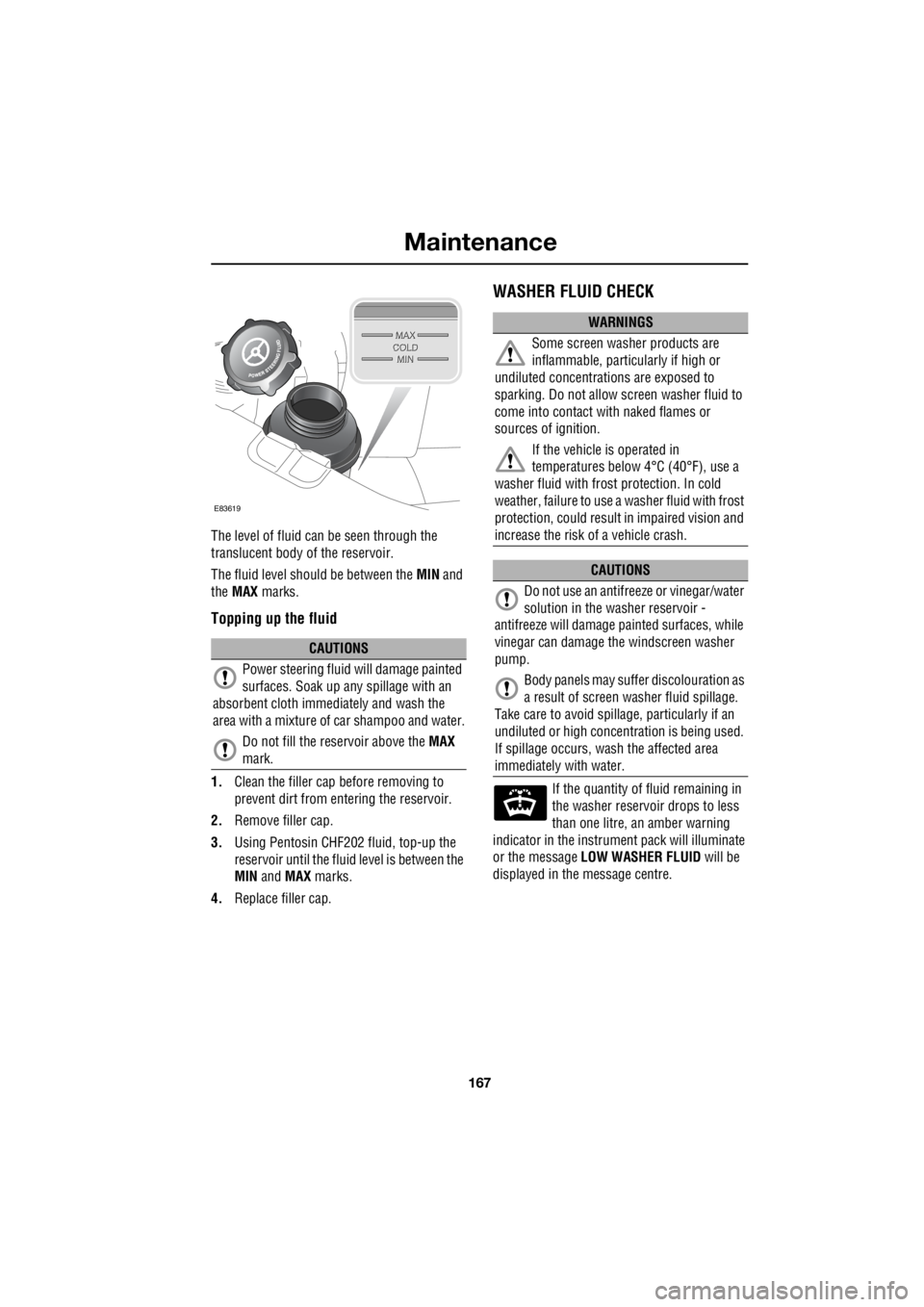
The level of fluid can be seen through the
translucent body of the reservoir.
The fluid level should be between the MIN and
the MAX marks.
Topping up the fluid
1.Clean the filler cap before removing to
prevent dirt from entering the reservoir.
2. Remove filler cap.
3. Using Pentosin CHF202 fluid, top-up the
reservoir until the flui d level is between the
MIN and MAX marks.
4. Replace filler cap.
WASHER FLUID CHECK
If the quantity of fluid remaining in
the washer reservoir drops to less
than one litre, an amber warning
indicator in the instrument pack will illuminate
or the message LOW WASHER FLUID will be
displayed in the message centre.
CAUTIONS
Power steering fluid will damage painted
surfaces. Soak up any spillage with an
absorbent cloth immediately and wash the
area with a mixture of car shampoo and water.
Do not fill the reservoir above the MAX
mark.
E83619
WARNINGS
Some screen washer products are
inflammable, particul arly if high or
undiluted concentrati ons are exposed to
sparking. Do not allow screen washer fluid to
come into contact with naked flames or
sources of ignition.
If the vehicle is operated in
temperatures below 4°C (40°F), use a
washer fluid with frost protection. In cold
weather, failure to use a washer fluid with frost
protection, could result in impaired vision and
increase the risk of a vehicle crash.
CAUTIONS
Do not use an antifree ze or vinegar/water
solution in the washer reservoir -
antifreeze will damage painted surfaces, while
vinegar can damage th e windscreen washer
pump.
Body panels may suff er discolouration as
a result of screen washer fluid spillage.
Take care to avoid spilla ge, particularly if an
undiluted or high concentr ation is being used.
If spillage occurs, wash the affected area
immediately with water.
Page 2994 of 3229

Index
274
L
Heated seats . . . . . . . . . . . . . . . . . . . . . . . 53
Heated windows and mirrors. . . . . . . . . . 104
Hill descent control . . . . . . . . . . . . . . . . . 137
Hill descent control (HDC)
Principle of operation . . . . . . . . . . . . . 136
Hints on driving with ABS . . . . . . . . . . . . 123
ABS and off-road driving. . . . . . . . . . . 124
ABS warning indicator . . . . . . . . . . . . 123
Electronic Brake Distribution (EBD) . . 124
Emergency Brake Assist (EBA) . . . . . . 124
I
Information messages . . . . . . . . . . . . . . . . 99 Main message centre . . . . . . . . . . . . . . 99
Messages . . . . . . . . . . . . . . . . . . . . . . 100
Inspecting safety system components . . 206
Instrument panel overview . . . . . . . . . . . . 97 Instrument panel . . . . . . . . . . . . . . . . . . 97
Interior lamps . . . . . . . . . . . . . . . . . . . . . . 76
Interior mirror . . . . . . . . . . . . . . . . . . . . . . 96 Auto dimming . . . . . . . . . . . . . . . . . . . . 96
Manual dimming . . . . . . . . . . . . . . . . . . 96
ISOFIX anchor points . . . . . . . . . . . . . . . . 67 Installing an ISOFIX child seat . . . . . . . 68
Tether anchorages . . . . . . . . . . . . . . . . 68
J
Jump starting . . . . . . . . . . . . . . . . . . . . . 173
K
Keys . . . . . . . . . . . . . . . . . . . . . . . . . . . . . 40
L
Lashing points . . . . . . . . . . . . . . . . . . . . . 208
Front . . . . . . . . . . . . . . . . . . . . . . . . . . 208
Rear . . . . . . . . . . . . . . . . . . . . . . . . . . 208
Levelling . . . . . . . . . . . . . . . . . . . . . . . . . 151
Lighting control . . . . . . . . . . . . . . . . . . . . . 72 Headlamp courtesy delay . . . . . . . . . . . 72
Main beam . . . . . . . . . . . . . . . . . . . . . . 72
Main switch panel . . . . . . . . . . . . . . . . . 72
Load carrying General information . . . . . . . . . . . . . . 147
Loading compact discs . . . . . . . . . . . . . . 245 Load all . . . . . . . . . . . . . . . . . . . . . . . . 245
Loading a CD - Single disc player . . . . 245
Loading a CD - Six disc player . . . . . . 245 Locking and unlocking . . . . . . . . . . . . . . . . 44
Drive-away locking . . . . . . . . . . . . . . . . . 44
Locking and unlocking from inside the vehicle . . . . . . . . . . . . . . . . . . . . . . . . 44
Mis-lock . . . . . . . . . . . . . . . . . . . . . . . . . 44
Luggage anchor points . . . . . . . . . . . . . . . 148
Reversible floor . . . . . . . . . . . . . . . . . . 148
Luggage covers . . . . . . . . . . . . . . . . . . . . 149 Fitting the luggage cover . . . . . . . . . . . 149
Operating the luggage cover. . . . . . . . . 149
M
Maintenance General information . . . . . . . . . . . . . . . 157
Technical specifications . . . . . . . . . . . . 169
Manual climate control . . . . . . . . . . . . . . . 102
Controls . . . . . . . . . . . . . . . . . . . . . . . . 102
Manual seats. . . . . . . . . . . . . . . . . . . . . . . . 48
Manual transmission . . . . . . . . . . . . . . . . 118
Mirrors . . . . . . . . . . . . . . . . . . . . . . . . . . . 104
MP3 file playback . . . . . . . . . . . . . . . . . . . 249
N
News broadcasts . . . . . . . . . . . . . . . . . . . 230 News station preference . . . . . . . . . . . . 230
O
Oil check . . . . . . . . . . . . . . . . . . . . . . . . . . 162
On or off control . . . . . . . . . . . . . . . . . . . . 223
Opening and closing the bonnet . . . . . . . . 160
Closing the bonnet . . . . . . . . . . . . . . . . 160
Opening the bonnet . . . . . . . . . . . . . . . 160
P
Parking aid . . . . . . . . . . . . . . . . . . . . . . . . 127 Principle of operation . . . . . . . . . . . . . . 126
Parking brake . . . . . . . . . . . . . . . . . . . . . . 124
Applying the parking brake . . . . . . . . . . 125
Parking on a slope . . . . . . . . . . . . . . . . 124
Releasing the parking brake . . . . . . . . . 125
Phonebook . . . . . . . . . . . . . . . . . . . . . . . . 266 Phonebook menu . . . . . . . . . . . . . . . . . 267
Power steering fluid check . . . . . . . . . . . . 166
Checking the fluid level. . . . . . . . . . . . . 166
Topping up the fluid . . . . . . . . . . . . . . . 167
Page 3025 of 3229
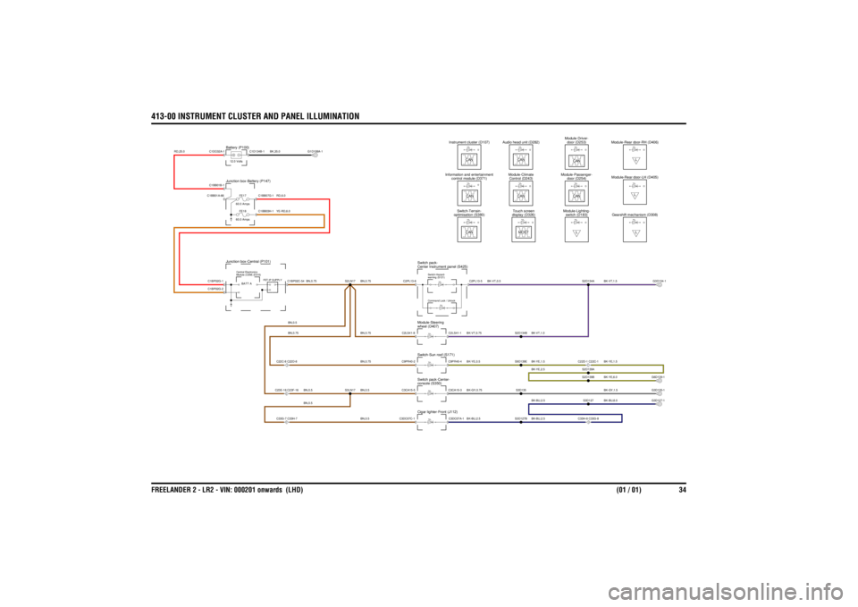
413-00 INSTRUMENT CLUSTER AND PANEL ILLUMINATIONFREELANDER 2 - LR2 - VIN: 000201 onwards (LHD) (01 / 01) 34
413-00 INSTRUMENT CLUSTER AND PANEL ILLUMINATION
BN,0.5BN,0.5BN,0.75BN,0.75BN,0.75
BN,0.5BN,0.75
BN,0.5BN,0.5
YE-RD,6.0RD,6.0
RD,25.0
BN,0.75
BK,35.0
BK-VT,0.75
BK-VT,1.0
BK-YE,1.5BK-GY,1.5
BK-BU,2.5
BK-YE,6.0BK-BU,6.0
BK-YE,0.5BK-GY,0.75BK-BU,2.5
BK-BU,2.5BK-YE,1.5BK-YE,2.5
BK-VT,1.5
BK-VT,0.5
C33G-7 C33H-7C22C-8 C22D-8C23E-16 C23F-16
FE17
60.0 AmpsFE18
60.0 Amps
Junction box-Battery (P147)Junction box-Central (P101)
Module (CEM) (D316)
Central Electronics
FET-IP SUPPLY
Battery (P100)12.0 Volts
wheel (D407)
Module-Steeringconsole (S350)
Switch pack-Center-Cigar lighter-Front (J112)Switch-Sun roof (S171)
C33H-8 C33G-8C22D-1 C22C-1
CAN
CAN
CANdoor (D254)
Module-Passenger-
Control (D243)
Module-Climate
control module (D371)
Information and entertainment
display (D326) Touch screen
Center Instrument panel (S425)
Switch pack-
Command Lock / Unlockwarning (S121)
Switch-Hazard-
optimisation (S380)
Switch-Terrain-
CAN
MOST
L
switch (D183)
Module-Lighting-
Audio head unit (D282)
Instrument cluster (D107)
CAN
CAN
CANdoor (D253)
Module-Driver-
Module-Rear door-LH (D405)Gearshift mechanism (D308)
LModule-Rear door-RH (D406)
LL
C2LS41-8C9PR40-2C3CA15-5C2PL13-6C3DC07C-1
S3LN17
C1BP02G-2C1BP02G-1C1BB01B-1C1BB01A-66C1DC02A-1
C1BB07G-1
BATT A
C1BP02C-54
C1BB03H-1
S2LN17
G1D108A-1
C1D134B-1
S2D134B
C2LS41-1C3DC07A-1C9PR40-4C3CA15-3
S3D127
S3D127BS3D135S9D139E
S2D139BS2D139A
G3D127-1G3D135-1G6D139-1
C2PL13-5
S2D134A
G3D134-1
Page 3089 of 3229
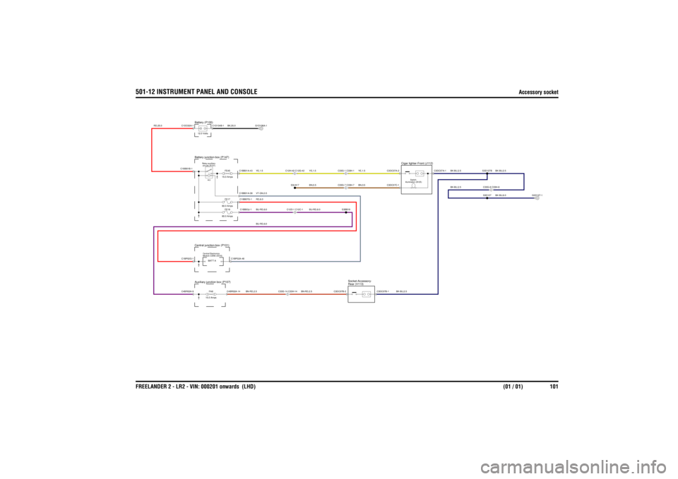
501-12 INSTRUMENT PANEL AND CONSOLE
Accessory socket
FREELANDER 2 - LR2 - VIN: 000201 onwards (LHD) (01 / 01) 101
501-12 INSTRUMENT PANEL AND CONSOLEAccessory socket
VT-GN,0.5
YE,1.5BN,0.5
BU-RD,6.0RD,6.0
BN-RD,2.5
BN-RD,2.5
RD,25.0
BU-RD,6.0YE,1.5
BU-RD,6.0YE,1.5BN,0.5
BK,35.0
BK-BU,2.5
BK-BU,6.0BK-BU,2.5
BK-BU,2.5BK-BU,2.5
Rear (V113)
Socket-Accessory-
Central junction-box (P101)
FA6
15.0 Amps
Auxiliary junction box (P107)
Module (CEM) (D316)
Central Electronics
C33G-14 C33H-14
FE17
60.0 AmpsFE19
60.0 AmpsFE45
15.0 Amps
Battery (P100)12.0 VoltsBattery junction-box (P147)
circuits (R101)
Relay-auxiliary-RE5
C12D-1 C12C-1C12H-42 C12G-42
C33G-7 C33H-7C33G-1 C33H-1
illumination (B125) Switch-Cigar lighter-Front (J112)
C33G-8 C33H-8
C4BR02A-9C1BP02G-1
C4BR02A-14C1BP02A-48
BATT A
C3DC07B-2
C1BB01B-1C1DC02A-1
C1BB03J-1C1BB07G-1C1BB01A-38C1BB01A-43
S3BB19
S3LN17
C1D134B-1
G1D108A-1
C3DC07B-1
C3DC07A-1
C3DC07C-1C3DC07A-2
S3D127S3D127B
G3D127-1
Page 3100 of 3229

08/20085
ABBREVIATIONS
........................................................................................................................................................................................................ 7
USING THIS PUBLICATION
Health and safety ............................................................................................................................................................................ 8
Using this publication ...................................................................................................................................................................... 8
Section numbering .......................................................................................................................................................................... 9
Circuit sheet numbering .................................................................................................................................................................. 9
Understanding the circuit diagrams ................................................................................................................................................ 9
204-04 WHEELS AND TIRES
Tire pressure monitoring system ................................................................................................................................................. 11
205-02 REAR DRIVE AXLE AND DIFFERENTIAL
..................................................................................................................................................................................................... 12
206-09 ANTI-LOCK CONTROL
..................................................................................................................................................................................................... 13
211-04 STEERING COLUMN
Clock spring ................................................................................................................................................................................. 15
303-06 STARTING SYSTEM
Ignition ......................................................................................................................................................................................... 16
303-14 ELECTRONIC ENGINE CONTROLS
Petrol ........................................................................................................................................................................................... 17
Diesel ........................................................................................................................................................................................... 22
307-01 AUTOMATIC TRANSMISSION
..................................................................................................................................................................................................... 27
412-01 CLIMATE CONTROL
Manual ......................................................................................................................................................................................... 28
Automatic ..................................................................................................................................................................................... 31
413-00 INSTRUMENT CLUSTER AND PANEL ILLUMINATION
..................................................................................................................................................................................................... 34
412-02 AUXILIARY CLIMATE CONTROL
Windshield heater ........................................................................................................................................................................ 35
Electric booster heater ................................................................................................................................................................. 36
Fuel fired booster heater .............................................................................................................................................................. 37
413-06 HORN
..................................................................................................................................................................................................... 38
413-08 INFORMATION AND MESSAGE CENTRE
..................................................................................................................................................................................................... 39
413-13 PARKING AID
..................................................................................................................................................................................................... 41
414-01 BATTERY, MOUNTING AND CABLES
Battery junction box - P6 .............................................................................................................................................................. 43
Battery junction box - D4 ............................................................................................................................................................. 46
Auxiliary junction box ................................................................................................................................................................... 50
Central junction box ..................................................................................................................................................................... 53
Ground distribution ...................................................................................................................................................................... 59
414-02 GENERATOR AND REGULATOR
Charging ...................................................................................................................................................................................... 64