instrument panel LAND ROVER FRELANDER 2 2006 Repair Manual
[x] Cancel search | Manufacturer: LAND ROVER, Model Year: 2006, Model line: FRELANDER 2, Model: LAND ROVER FRELANDER 2 2006Pages: 3229, PDF Size: 78.5 MB
Page 2259 of 3229
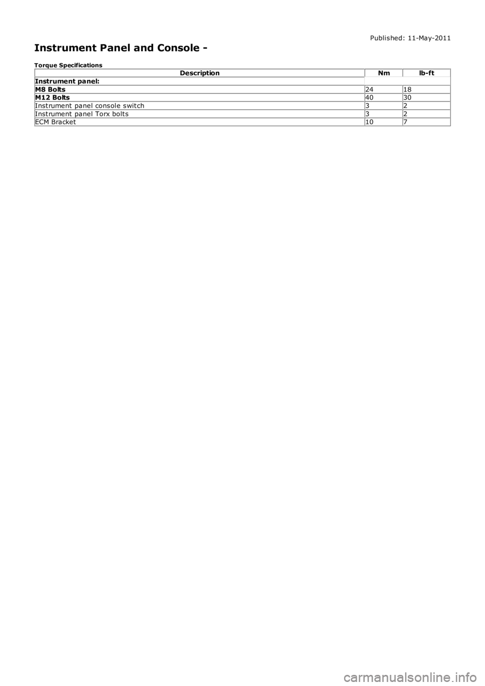
Publi s hed: 11-May-2011
Instrument Panel and Console -
Torque SpecificationsDescriptionNmlb-ft
Instrument panel:
M8 Bolts2418M12 Bolts4030
Inst rument panel cons ol e s wit ch32
Inst rument panel Torx bolt s32ECM Bracket107
Page 2260 of 3229
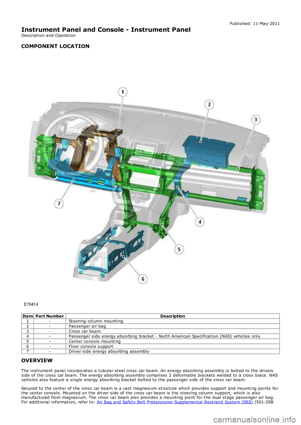
Publi s hed: 11-May-2011
Instrument Panel and Console - Instrument Panel
Des cript ion and Operat ion
COMPONENT LOCATION
ItemPart NumberDescription1-St eering col umn mounti ng
2-Pas s enger air bag
3-Cross car beam4-Pas s enger s ide energy abs orbing bracket - Nort h American Speci fi cat ion (NAS) vehi cl es onl y
5-Cent er cons ol e mounti ng
6-Fl oor consol e s upport7-Driver s ide energy abs orbing as s embly
OVERVIEW
The ins t rument panel i ncorporat es a t ubul ar st eel cross car beam. An energy abs orbing as s embly i s bolt ed to the driverss ide of t he cros s car beam. The energy abs orbing as s embly compri s es 2 deformabl e brackets wel ded to a cros s brace. NASvehi cl es als o feat ure a s ingle energy abs orbi ng bracket bolt ed t o t he pass enger s i de of the cros s car beam.
Secured to the center of t he cros s car beam is a cas t magnes i um s t ructure which provides s upport and mounti ng points fort he cent er cons ol e. Mount ed on t he dri ver s ide of t he cros s car beam is the s t eering column support , which i s als omanufactured from magnes ium. The cros s car beam als o provi des a mounti ng poi nt for the dual s t age pas s enger air bag.For addit ional informat ion, refer t o: Air Bag and Safet y Belt Pretens ioner Supplement al Res traint Syst em (SRS) (501-20B
Page 2262 of 3229
Publi s hed: 11-May-2011
Instrument Panel and Console - Instrument PanelTD4 2.2L Diesel
Removal and Inst all ati on
Removal
Make t he SRS s ys t em s afe.
Refer t o: Supplement al Res t raint Sys tem (SRS) Depowering andRepowering (501-20, General Procedures ).
1.
Remove t he winds hield wiper motor.
Refer t o: W i nds hield W i per Mot or (501-16 W ipers and W as hers ,Removal and Ins tall ati on).
2.
Evacuate the A/C s ys tem.
Refer t o: Air Condi ti oning (A/C) Sys tem Recovery, Evacuati on andCharging (412-00 Cl imat e Control Sys t em - General Informat ion,General Procedures).
3.
Remove both front door ass embl ies .
Refer t o: Front Door (501-03 Body Clos ures , Removal andInst all at ion).
4.
Remove both A-pil lar upper t ri m panels .
Refer t o: A-Pil lar Tri m Panel (501-05 Int erior Trim andOrnament ati on, Removal and Ins tal lat ion).
5.
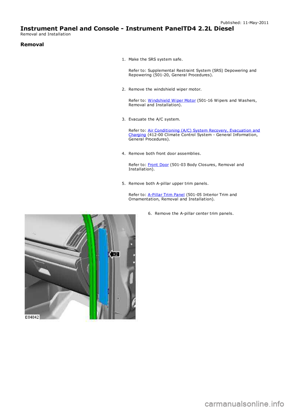
Remove t he A-pi llar center t rim panels .6.
Page 2271 of 3229
Publi s hed: 11-May-2011
Instrument Panel and Console - Instrument PanelI6 3.2L Petrol
Removal and Inst all ati on
Removal
Make t he SRS s ys t em s afe.
Refer t o: Supplement al Res t raint Sys tem (SRS) Depowering and
Repowering (501-20, General Procedures ).
1.
Remove t he winds hield wiper motor.
Refer t o: W i nds hield W i per Mot or (501-16 W ipers and W as hers ,
Removal and Ins tall ati on).
2.
Evacuate the A/C s ys tem.
Refer t o: Air Condi ti oning (A/C) Sys tem Recovery, Evacuati on and Charging (412-00 Cl imat e Control Sys t em - General Informat ion,
General Procedures).
3.
Remove both front door ass embl ies .
Refer t o: Front Door (501-03 Body Clos ures , Removal and
Inst all at ion).
4.
Remove both A-pil lar upper t ri m panels .
Refer t o: A-Pil lar Tri m Panel (501-05 Int erior Trim and
Ornament ati on, Removal and Ins tal lat ion).
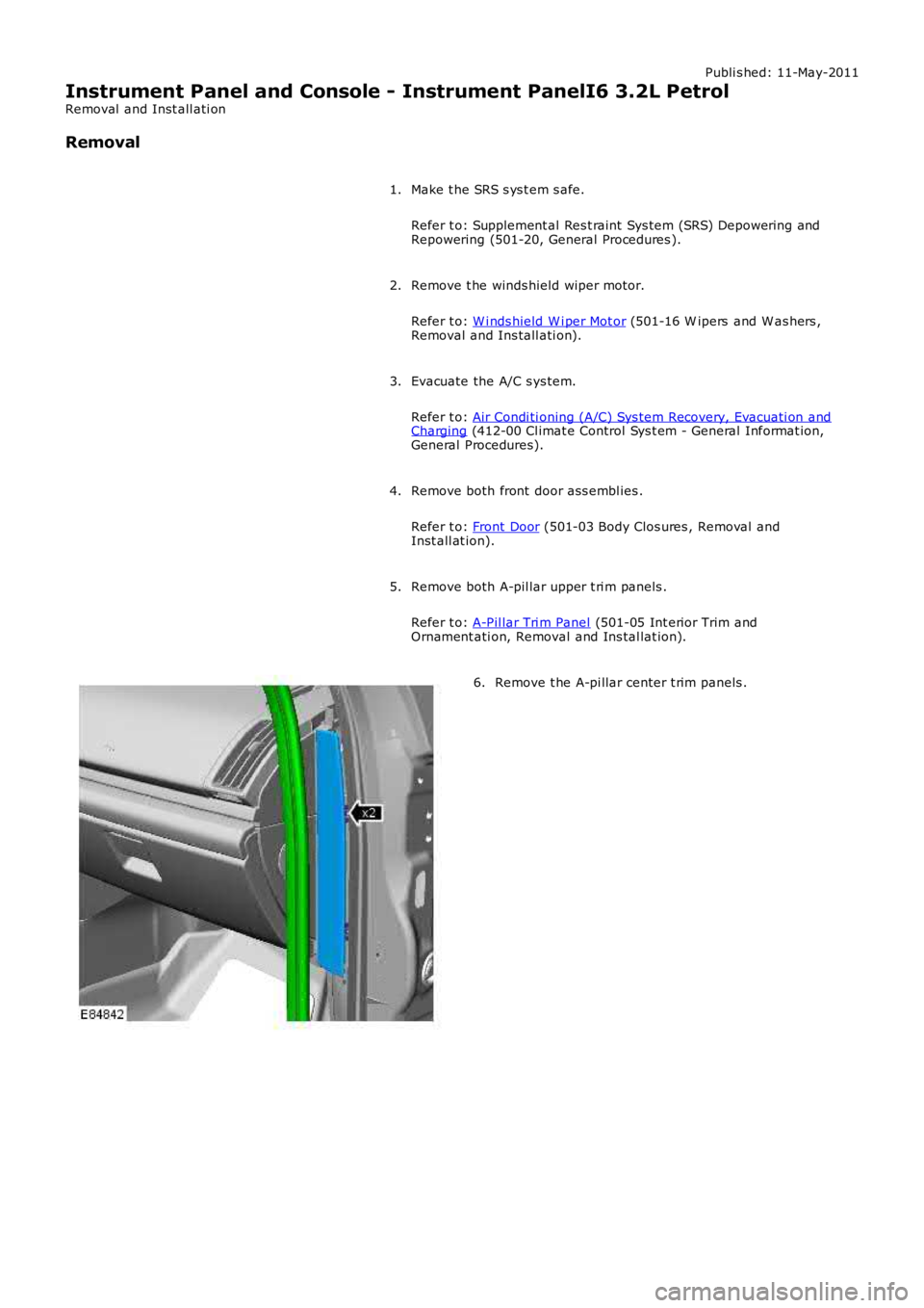
5. Remove t he A-pi llar center t rim panels .
6.
Page 2280 of 3229
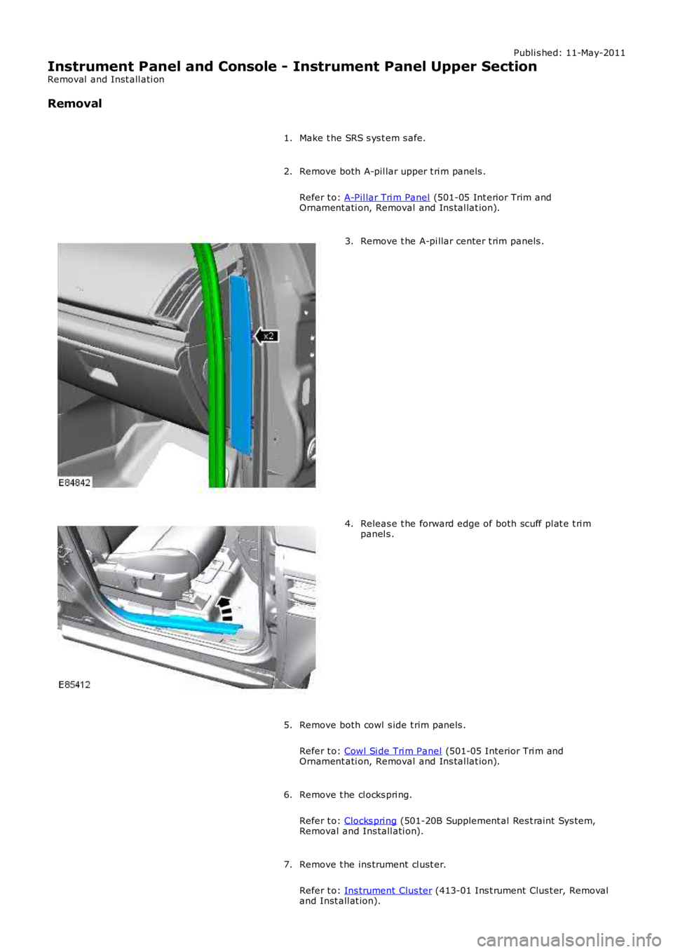
Publi s hed: 11-May-2011
Instrument Panel and Console - Instrument Panel Upper Section
Removal and Inst all ati on
Removal
Make t he SRS s ys t em s afe.1.
Remove both A-pil lar upper t ri m panels .
Refer t o: A-Pil lar Tri m Panel (501-05 Int erior Trim andOrnament ati on, Removal and Ins tal lat ion).
2.
Remove t he A-pi llar center t rim panels .3.
Releas e t he forward edge of both scuff pl at e t ri mpanel s .4.
Remove both cowl s ide t rim panels .
Refer t o: Cowl Si de Tri m Panel (501-05 Interior Tri m andOrnament ati on, Removal and Ins tal lat ion).
5.
Remove t he cl ocks pri ng.
Refer t o: Clocks pri ng (501-20B Supplement al Res t raint Sys tem,Removal and Ins tall ati on).
6.
Remove t he ins trument cl ust er.
Refer t o: Ins trument Clus ter (413-01 Ins t rument Clus t er, Removaland Inst all at ion).
7.
Page 2295 of 3229
Publi s hed: 11-May-2011
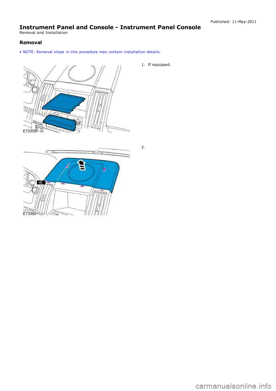
Instrument Panel and Console - Instrument Panel Console
Removal and Inst all ati on
Removal
• NOTE: Removal s t eps in t his procedure may cont ain i nst all ati on det ail s.
If equi pped.1.
2.
Page 2298 of 3229
Publi s hed: 11-May-2011
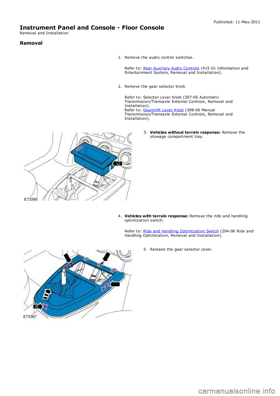
Instrument Panel and Console - Floor Console
Removal and Inst all ati on
Removal
Remove t he audi o cont rol s wit ches .
Refer t o: Rear Auxil iary Audi o Control s (415-01 Informat ion andEntertai nment Sys tem, Removal and Ins tal lat ion).
1.
Remove t he gear s elector knob.
Refer t o: Sel ect or Lever Knob (307-05 Aut omati cTrans mi ss ion/Transaxle Ext ernal Cont rol s , Removal andInst all at ion).Refer t o: Gears hi ft Lever Knob (308-06 ManualTrans mi ss ion/Transaxle Ext ernal Cont rol s , Removal andInst all at ion).
2.
Vehicles w ithout terrain response: Remove thes towage compart ment tray.3.
Vehicles w ith terrain response: Remove t he ri de and handl ingopti mizat ion s wit ch.
Refer t o: Ride and Handli ng Opti mizati on Swit ch (204-06 Ride andHandling Opti mizati on, Removal and Ins t al lat ion).
4.
Releas e t he gear s elector cover.5.
Page 2302 of 3229
Publi s hed: 11-May-2011
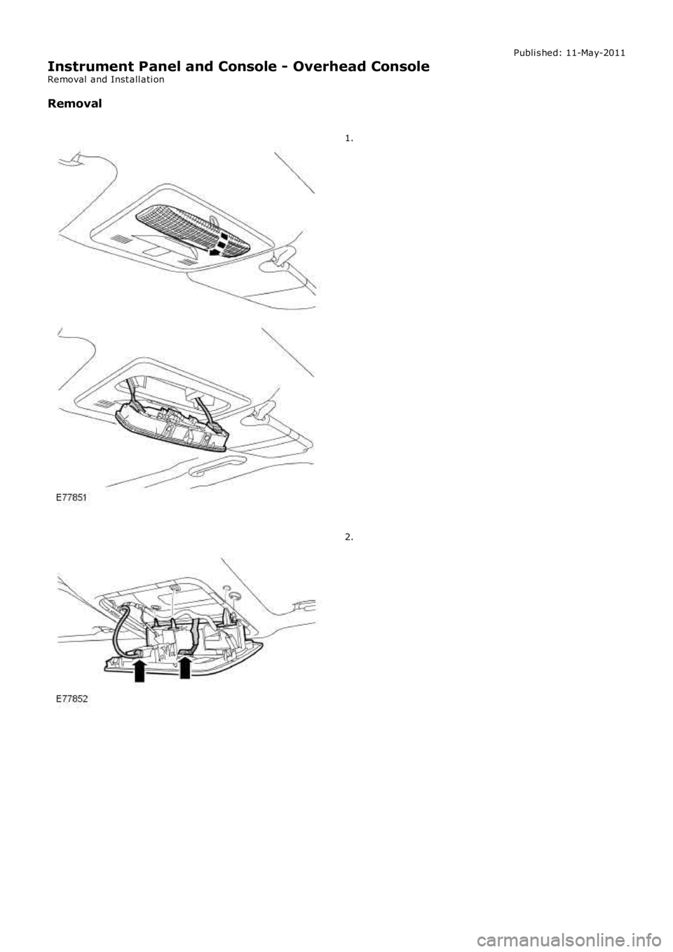
Instrument Panel and Console - Overhead Console
Removal and Inst all ati on
Removal
1.
2.
Page 2304 of 3229
Publi s hed: 11-May-2011
Instrument Panel and Console - Glove Compartment
Removal and Inst all ati on
Removal
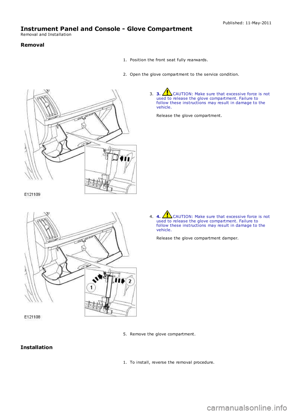
Pos it ion t he front seat ful ly rearwards .1.
Open t he glove compart ment to the s ervi ce condit ion.2.
3. CAUTION: Make s ure that exces si ve force is notus ed to rel eas e t he glove compart ment. Fail ure t ofol low thes e ins t ructi ons may res ult i n damage t o thevehicle.
Releas e t he glove compartment .
3.
4. CAUTION: Make s ure that exces si ve force is notus ed to rel eas e t he glove compart ment. Fail ure t ofol low thes e ins t ructi ons may res ult i n damage t o thevehicle.
Releas e t he glove compartment damper.
4.
Remove t he glove compartment .5.
Installation
To i nst all , revers e t he removal procedure.1.
Page 2314 of 3229
RF Receiver
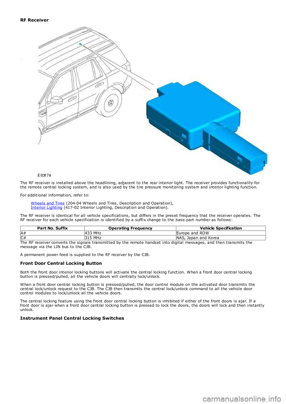
The RF receiver is inst all ed above the headlining, adjacent t o t he rear interi or light . The receiver provides functi onal ity forthe remote cent ral locking system, and i s als o us ed by t he t ire pres sure monit oring s ys tem and int erior li ghting function.
For addit ional informat ion, refer t o:
W heels and Tires (204-04 W heel s and Tires , Des cription and Operat ion),Interi or Lighting (417-02 Int erior Li ghting, Des cript ion and Operati on).
The RF receiver is identical for all vehi cle s peci ficati ons, but di ffers in the preset frequency that the recei ver operates. TheRF receiver for each vehi cle s pecificati on is identi fied by a suffi x change to t he bas e part number as fol lows :
Part No. SuffixOperating FrequencyVehicle Specification
A#433 MHzEurope and ROWC#315 MHzNAS, Japan and KoreaThe RF receiver converts the signals transmit ted by the remote hands et into digi tal mess ages , and t hen trans mits themess age vi a the LIN bus to t he CJB.
A permanent power feed is suppli ed to t he RF recei ver by the CJB.
Front Door Central Locking Button
Both the front door i nt erior locking but tons will acti vate the cent ral locking function. W hen a front door central l ockingbutton is pres sed/pulled, all the vehicle doors wil l centrall y l ock/unlock.
W hen a front door central l ocking butt on is press ed/pull ed, t he door control module on the act ivated door t ransmit s thecent ral lock/unlock request to t he CJB. The CJB then t rans mi ts the central lock/unlock command to all t he vehicl e doorcont rol modul es to l ock/unl ock all the vehi cle doors .
The central locking feature us ing the front door central l ocking butt on is inhi bi ted i f either of t he front doors i s ajar. If afront door i s ajar when a front door cent ral locking button is pres sed to lock the doors, the doors will lock and then i ns tantl yunlock.
Instrument Panel Central Locking Switches