wiring LAND ROVER FRELANDER 2 2006 User Guide
[x] Cancel search | Manufacturer: LAND ROVER, Model Year: 2006, Model line: FRELANDER 2, Model: LAND ROVER FRELANDER 2 2006Pages: 3229, PDF Size: 78.5 MB
Page 583 of 3229
The SRS el ect ri cal connectors are uni que. DO NOT force, orat tempt t o connect electrical connect ors t o t he wrong socket s .
Driver air bag module ins tall ati on can be confirmed by heari ng2 audibl e clicks , 1 for each s pring. The module edges s houl d als o beflus h wit h t he s teering wheel.
Inst all t he dri ver air bag modul e.
If ins tal led, connect t he SRS ride-down el ect ri cal connectorconcealed at t he rear of t he s teeri ng col umn.6.
Secure t he wiring harnes s t o t he s teeri ng column.7.
Connect t he s teeri ng col umn el ect ri cal connectors.8.
Inst all t he s teeri ng col umn upper cowl .9.
Inst all t he s teeri ng col umn l ower cowl.10.
Inst all t he dri ver l ower ai r bag modul e.
Refer t o: Dri ver Lower Air Bag Module (501-20B SupplementalRes traint Sys t em, Removal and Inst all at ion).
11.
Connect t he batt ery ground cable.
Refer t o: Specificati ons (414-00 Bat tery and Charging Sys tem -General Informat ion, Specificati ons).
12.
If a new s t eering column has been i nst all ed, confi gure t he s teeri ngcolumn l ock us i ng Land Rover approved di agnos t ic equipment.13.
Page 604 of 3229
DescriptionNmlb-ft
Cams haft beari ng hous ing to cyli nder head bolt sAA
Camshaft drive sprocket boltsExhaus t75 + 90°55 + 90°
Inlet11081
Cyli nder head bolt sAACyli nder head wiring harnes s mount ing bolt s65
Di ps t ick t ube bol t107
Engine i ns ulat or lower bolt s11081Engine i ns ulat or lower heat s hield Torx s crew107
Engine i ns ulat or upper bolt s11081
Engine mount bracket LH:M8*2518
M12*8059
Engine mount LH bolts175129Engine mount RH bolts8059
Engine mount bracket RH bolt:
M10*4533M12*8059
Flywheel flexplat e bolt s45 + 50°33 + 50°
Exhaus t manifold bol tsAAIntake manifold bol ts1612
Lifti ng bracket bol ts4835
Lower inlet mani fold bol ts107Lubricant drain plug3828
Oi l cooler as sembl y t o block ret aining bol ts107
Oi l cooler hos e bolt s107Oi l fil ter2518
Oi l level s ensor bolt86
Oil pan bolts:M71713
M104533
Oi l pump adjus ter bolt1713Oi l pump lock adjus ter s leeve bolt86
Oi l st rai ner pi ck-up ass embly bol t1713
Oi l squirt jet65Throt tl e body to block support bolt107
Throt tl e body s crews*86
Timing chain t ensi oner bolt107Timing cover bolt sAA
VVT s olenoid107
VVT unit retai ni ng boltAA* New nuts/bolts must be fitted
A = refer to procedure for correct torque sequence
Page 678 of 3229
Publi s hed: 11-May-2011
Engine - I6 3.2L Petrol - Exhaust Manifold
Removal and Inst all ati on
Special T ool(s) 310-121
W rench, H02S
Removal W ARNING: Observe due care when worki ng near a hot exhaust s ys tem.
1. W ARNING: Make sure t o s upport the vehicle wit h axle
s tands .
Rais e and s upport t he vehi cl e.
1.
Remove t he engi ne cover.
Refer t o: Engi ne Cover - I6 3.2L Pet rol (501-05 Int eri or Trim and
Ornament ati on, Removal and Ins tal lat ion).
2.
Remove t he cat alyti c convert ers .
Refer t o: Cat alyt ic Converter (309-00A Exhaus t Syst em - I6 3.2L
Petrol, Removal and Ins tall ati on).
3.
Remove t he RH fender s plas h s hield.
Refer t o: Fender Spl ash Shi eld (501-02 Front End Body Panel s ,
Removal and Ins tall ati on).
4.
Di sconnect t he heat ed oxygen s ens ors (HO2S) el ect ri cal connectors .
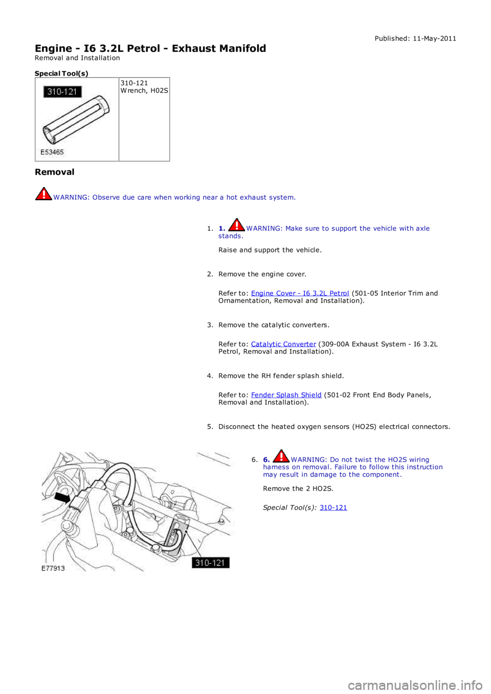
5. 6. W ARNING: Do not twi s t the HO2S wiring
harnes s on removal . Fai lure to foll ow t his i ns t ructi on
may res ul t in damage to t he component .
Remove t he 2 HO2S.
Speci al Tool (s ): 310-121 6.
Page 682 of 3229
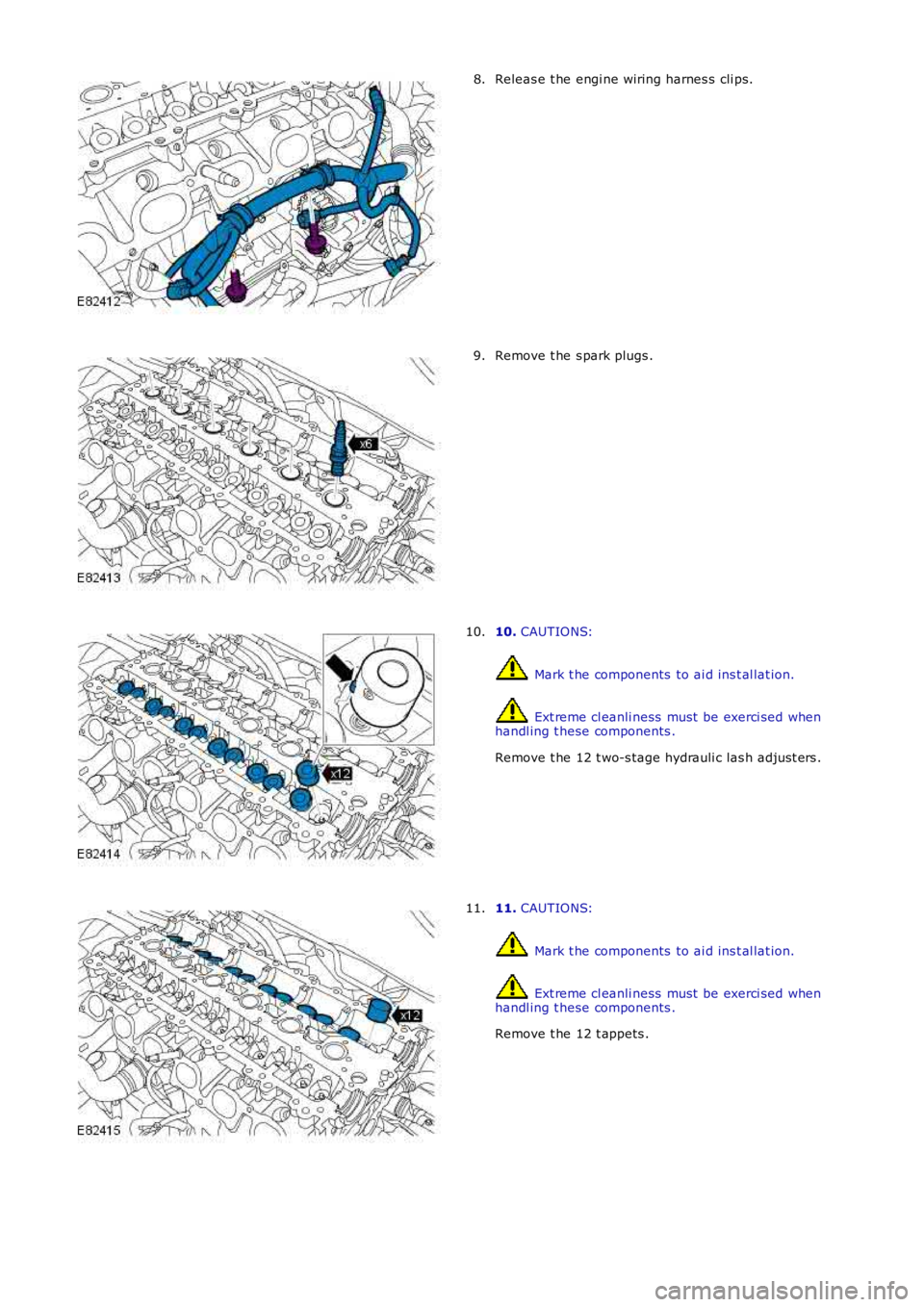
Releas e t he engi ne wiring harnes s cli ps.8.
Remove t he s park plugs .9.
10. CAUTIONS:
Mark t he components to ai d ins t al lat ion.
Ext reme cl eanli ness must be exerci sed whenhandl ing t hese components .
Remove t he 12 t wo-s tage hydrauli c las h adjus t ers .
10.
11. CAUTIONS:
Mark t he components to ai d ins t al lat ion.
Ext reme cl eanli ness must be exerci sed whenhandl ing t hese components .
Remove t he 12 t appets .
11.
Page 685 of 3229
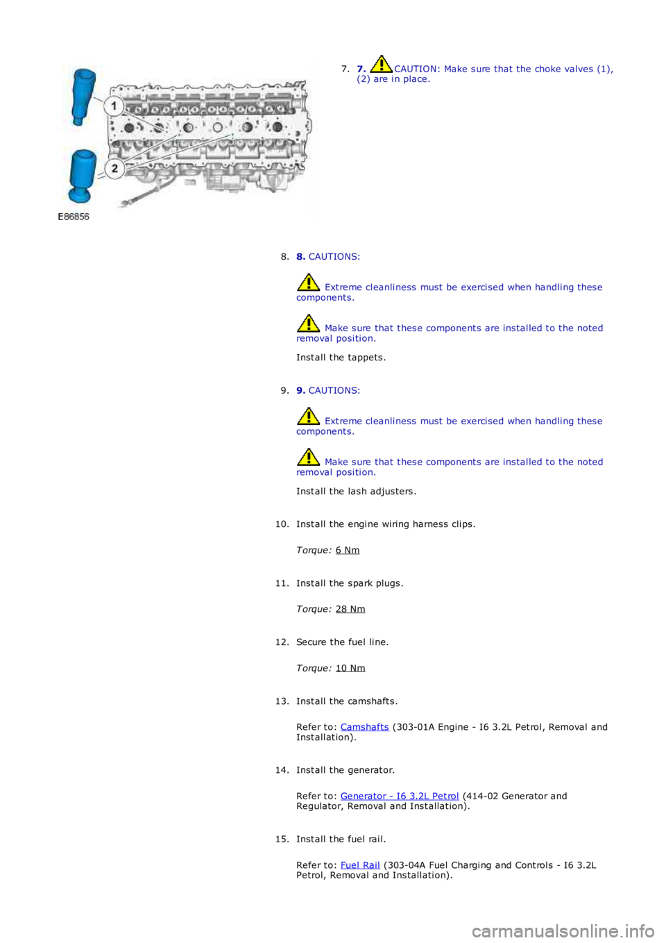
7. CAUTION: Make s ure that the choke valves (1),
(2) are i n place.
7.
8. CAUTIONS: Ext reme cl eanli ness must be exerci sed when handli ng t hes e
component s. Make s ure that t hes e component s are ins tal led t o t he noted
removal posi ti on.
Inst all t he tappets .
8.
9. CAUTIONS: Ext reme cl eanli ness must be exerci sed when handli ng t hes e
component s. Make s ure that t hes e component s are ins tal led t o t he noted
removal posi ti on.
Inst all t he las h adjus ters .
9.
Inst all t he engi ne wiring harnes s cli ps.
T orque: 6 Nm 10.
Inst all t he s park plugs .
T orque: 28 Nm 11.
Secure t he fuel li ne.
T orque: 10 Nm 12.
Inst all t he camshaft s .
Refer t o: Camshafts (303-01A Engine - I6 3.2L Pet rol , Removal and
Inst all at ion).
13.
Inst all t he generat or.
Refer t o: Generator - I6 3.2L Pet rol (414-02 Generator and
Regulator, Removal and Ins t allat ion).
14.
Inst all t he fuel rai l.
Refer t o: Fuel Rail (303-04A Fuel Chargi ng and Cont rol s - I6 3.2L
Petrol, Removal and Ins tall ati on).
15.
Page 744 of 3229
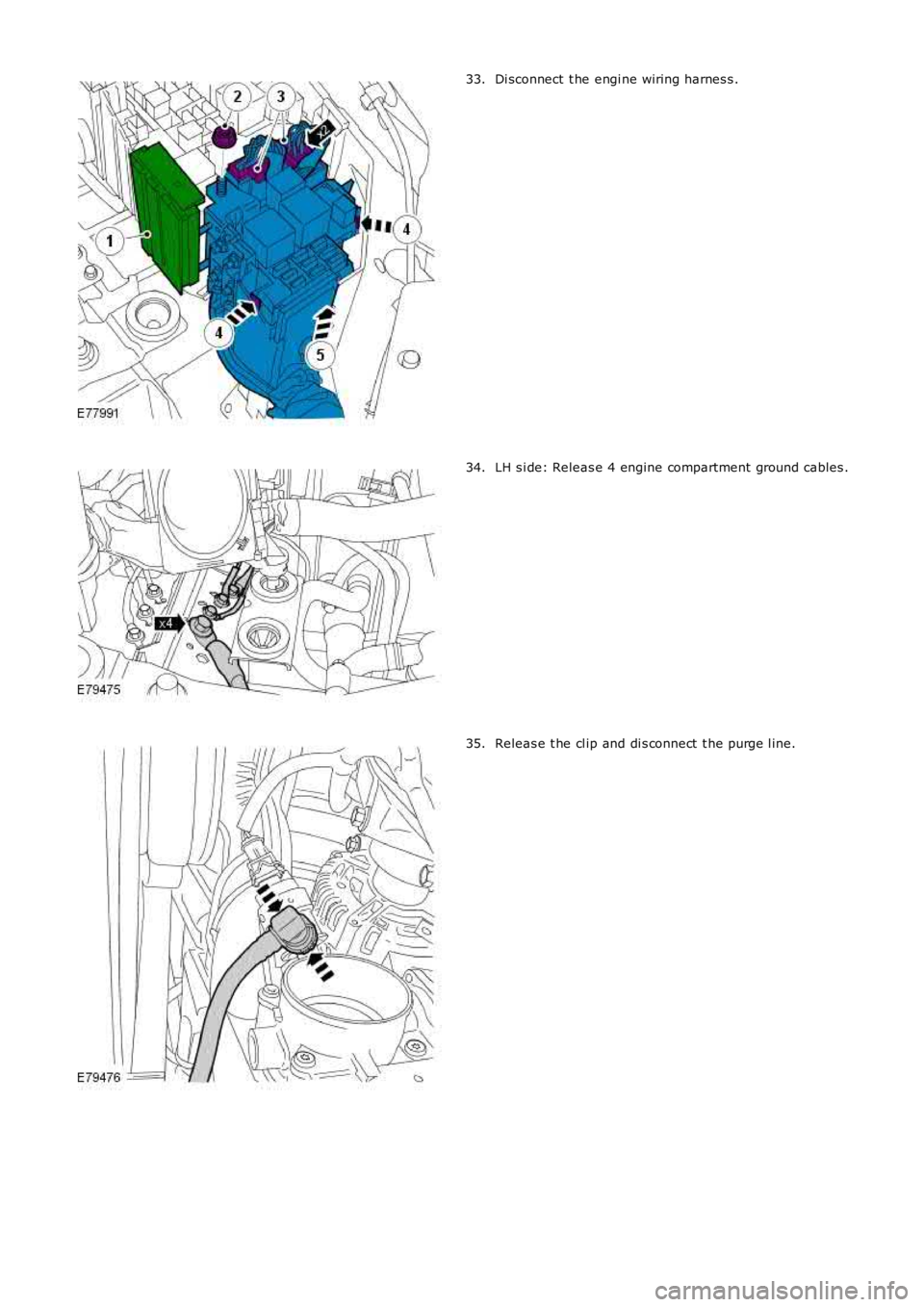
Di sconnect t he engi ne wiring harnes s .33.
LH s i de: Releas e 4 engine compartment ground cables .34.
Releas e t he cl ip and di s connect t he purge l ine.35.
Page 749 of 3229
Stage 1:
Stage 2:
T orque:
40 Nm Inst all t he cool ant expans i on tank.
T orque: 10 Nm 8.
Connect t he purge l ine.
9.
Connect t he engi ne compartment ground cables .
T orque: M8 25 Nm M6
10 Nm 10.
Secure t he engi ne wiring harnes s .
T orque: 10 Nm 11.
Inst all t he RH ground cable.
T orque: 10 Nm 12.
13. CAUTIONS: A new O-ri ng s eal i s to be ins tal led.
Ext reme cl eanli ness must be exerci sed when handli ng t hes e
component s.
Connect t he fuel li ne.
13.
Inst all t he transmis si on fluid cooler.
14.
Connect t he cool ant t op hos e.
15.
Connect t he cool ant bot tom hos e.
16.
Connect t he cool ing fan electrical connect or.
17.
Inst all t he RH halfs haft s upport .
T orque: 25 Nm 18.
Inst all t he LH halfshaft.
19.
W it h ass i st ance, i ns t all the hal fs haft t o t he hub.
20.
Inst all t he hal fs haft s .
T orque: 45 Nm 80°21.
Connect t he s el ect or cabl e to the trans mi ss i on.
22.
Connect t he low pres sure li ne t o t he power s t eering pump.
23.
Page 822 of 3229
"Make s ure t hat a new component i s ins t al led. "
Make s ure that t he mat ing faces are clean and free of foreign
mat eri al .
Inst all t he EGR pipe.
T orque: 10 Nm At tach t he s pi ll ret urn li ne.
11.
Connect and s ecure t he fuel inject or wiring harnes s electrical
connectors.
T orque: 10 Nm 12.
Inst all t he breather li ne.
13.
Inst all t he fuel fi lt er.
Refer t o: Fuel Fil ter (310-01B Fuel Tank and Lines - TD4 2.2L Dies el ,
Removal and Ins tall ati on).
14.
Connect t he batt ery ground cable.
Refer t o: Specificati ons (414-00 Bat tery and Charging Sys tem -
General Informat ion, Specificati ons).
15.
Page 833 of 3229
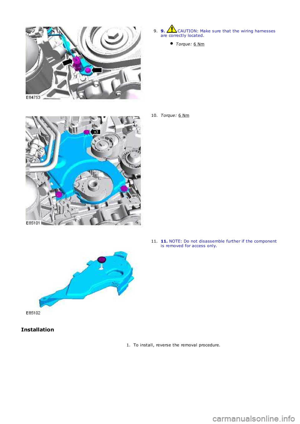
9. CAUTION: Make s ure that the wiring harnes s es
are correctl y located.
T orque: 6 Nm 9.
T orque:
6 Nm 10.
11.
NOTE: Do not dis ass emble further if t he component
i s removed for acces s onl y.
11.
Installation To i nst all , revers e t he removal procedure.
1.
Page 900 of 3229
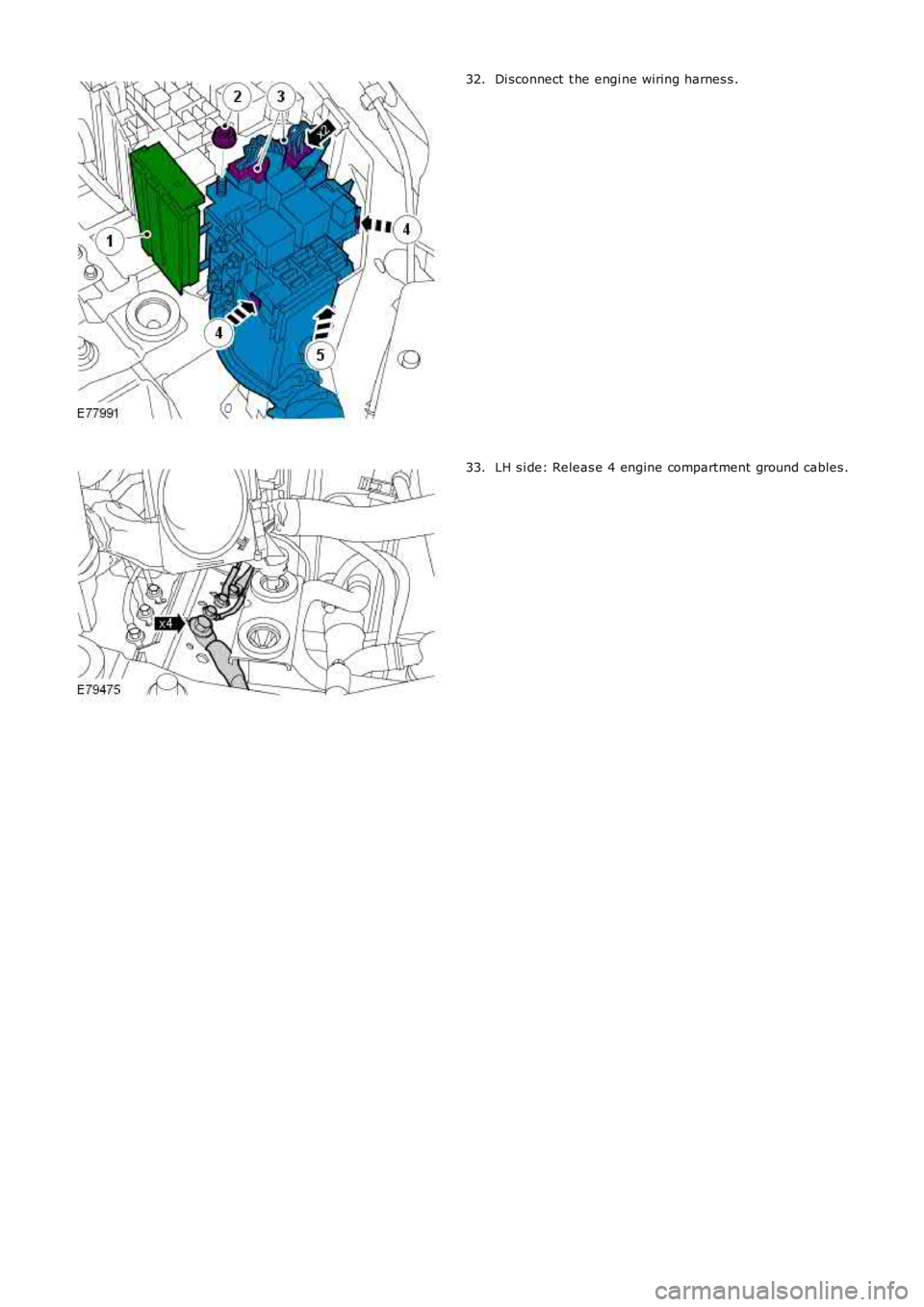
Di sconnect t he engi ne wiring harnes s .32.
LH s i de: Releas e 4 engine compartment ground cables .33.