wiring LAND ROVER FRELANDER 2 2006 Service Manual
[x] Cancel search | Manufacturer: LAND ROVER, Model Year: 2006, Model line: FRELANDER 2, Model: LAND ROVER FRELANDER 2 2006Pages: 3229, PDF Size: 78.5 MB
Page 1865 of 3229
1
1
1
1
1
1
1
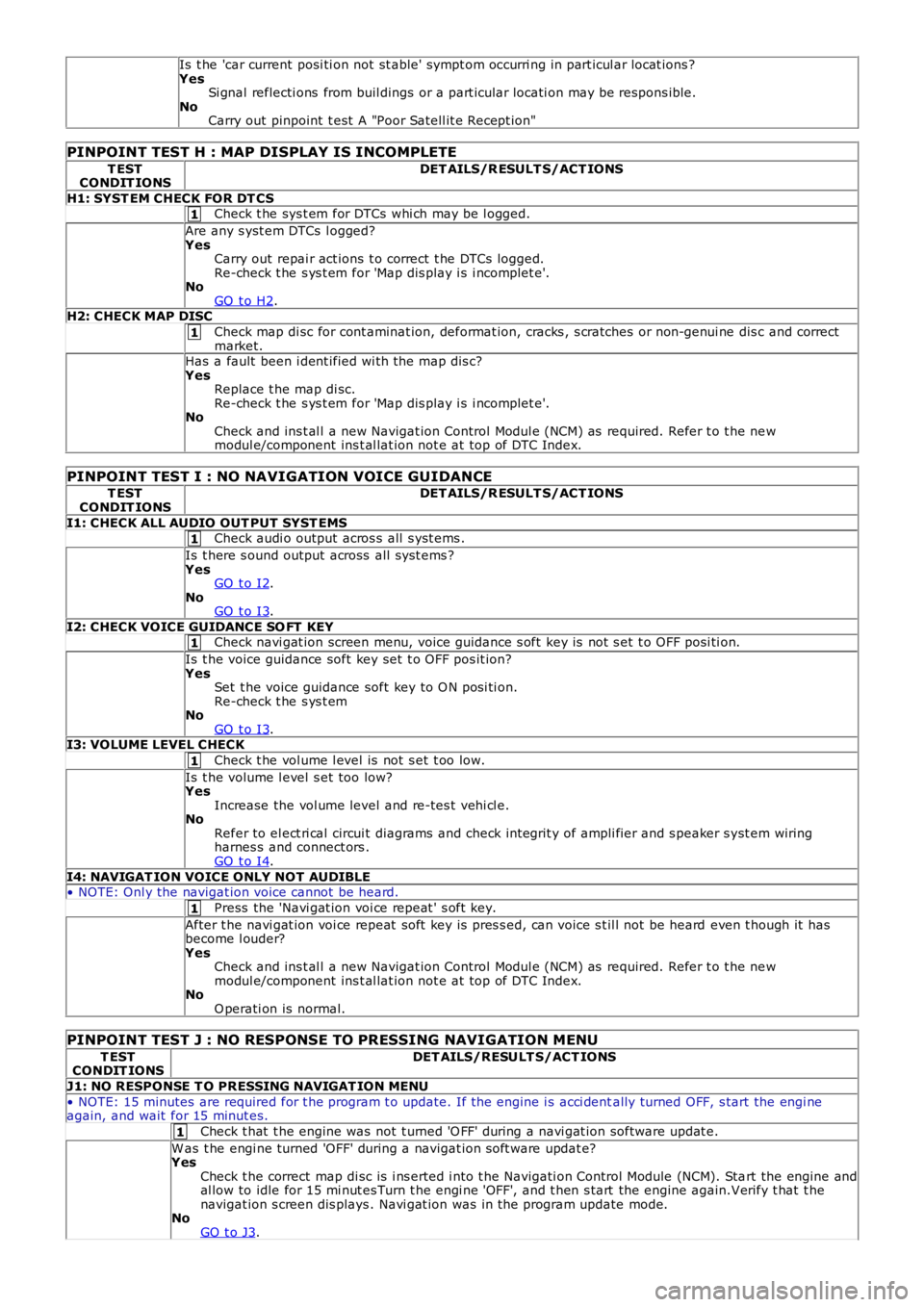
Is t he 'car current posi ti on not st able' sympt om occurri ng in part icul ar locat ions ?YesSi gnal reflecti ons from buil dings or a part icular locati on may be respons ible.NoCarry out pinpoint t est A "Poor Satell it e Recept ion"
PINPOINT TEST H : MAP DISPLAY IS INCOMPLETE
T ESTCONDIT IONSDET AILS/R ESULT S/ACT IONS
H1: SYST EM CHECK FOR DT CSCheck t he sys t em for DTCs whi ch may be l ogged.
Are any s yst em DTCs l ogged?YesCarry out repai r act ions t o correct t he DTCs logged.Re-check t he s ys t em for 'Map dis play i s i ncomplet e'.NoGO t o H2.H2: CHECK MAP DISC
Check map di sc for cont aminat ion, deformat ion, cracks , s cratches or non-genui ne dis c and correctmarket.Has a fault been i dent ified wi th the map dis c?YesReplace t he map di sc.Re-check t he s ys t em for 'Map dis play i s i ncomplet e'.NoCheck and ins t al l a new Navigat ion Control Modul e (NCM) as required. Refer t o t he newmodul e/component ins t al lat ion not e at top of DTC Index.
PINPOINT TEST I : NO NAVIGATION VOICE GUIDANCE
T ESTCONDIT IONSDET AILS/R ESULT S/ACT IONS
I1: CHECK ALL AUDIO OUT PUT SYST EMSCheck audi o output acros s all s yst ems .
Is t here s ound output across all s ys t ems ?YesGO t o I2.NoGO t o I3.
I2: CHECK VOICE GUIDANCE SO FT KEYCheck navi gat ion screen menu, voice guidance s oft key is not s et t o OFF posi ti on.
Is t he voice guidance soft key set t o OFF pos it ion?YesSet t he voice guidance soft key to O N posi ti on.Re-check t he s ys t emNoGO t o I3.I3: VOLUME LEVEL CHECK
Check t he vol ume l evel is not s et t oo low.
Is t he volume l evel s et too low?YesIncrease the vol ume level and re-tes t vehi cl e.NoRefer to el ect ri cal circui t diagrams and check int egrit y of ampli fier and s peaker s yst em wiringharnes s and connect ors .GO t o I4.
I4: NAVIGAT ION VOICE ONLY NOT AUDIBLE• NOTE: Onl y the navigat ion voice cannot be heard.
Press the 'Navi gat ion voi ce repeat ' s oft key.
After t he navi gat ion voi ce repeat soft key is pres s ed, can voice s t il l not be heard even t hough it hasbecome l ouder?YesCheck and ins t al l a new Navigat ion Control Modul e (NCM) as required. Refer t o t he newmodul e/component ins t al lat ion not e at top of DTC Index.NoO perati on is normal.
PINPOINT TEST J : NO RESPONSE TO PRESSING NAVIGATION MENU
T ESTCONDIT IONSDET AILS/RESULT S/ACT IONS
J1: NO RESPONSE T O PRESSING NAVIGAT ION MENU
• NOTE: 15 minutes are required for t he program t o update. If the engine i s acci dentally turned OFF, s tart the engi neagain, and wait for 15 minut es.
Check t hat t he engine was not t urned 'O FF' during a navi gat ion software updat e.
W as t he engi ne turned 'OFF' during a navigat ion s oft ware updat e?YesCheck t he correct map di sc is i ns erted i nto t he Navigati on Control Module (NCM). Start the engine andal low to idle for 15 mi nut es Turn t he engi ne 'OFF', and t hen s tart the engine again.Verify t hat t henavigat ion s creen dis plays . Navi gat ion was in the program update mode.NoGO t o J3.
Page 1962 of 3229
Publi s hed: 11-May-2011
Module Communications Network - Communications Network
Des cript ion and Operat ion
OVERVIEW
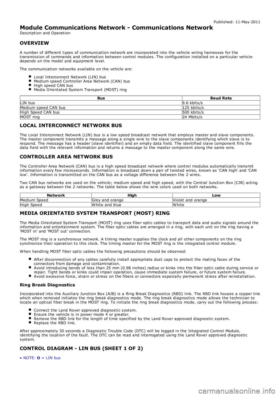
A number of different t ypes of communicati on network are incorporated into the vehicle wiring harnes s es for t het ransmis s ion of commands and informat ion between control modul es. The confi gurati on ins tal led on a parti cul ar vehicl edepends on t he model and equi pment level .
The communicati on net works avail abl e on t he vehi cl e are:
Local Int erconnect Network (LIN) busMedium speed Controll er Area Network (CAN) busHigh speed CAN busMedia O rient ated Sys tem Trans port (MO ST) ring
BusBaud Rate
LIN bus9.6 kbit s /s
Medium s peed CAN bus125 kbi ts /sHi gh Speed CAN bus500 kbi ts /s
MOST ring24 Mbit s/s
LOCAL INTERCONNECT NETWORK BUS
The Local Int erconnect Network (LIN) bus is a low s peed broadcas t net work that employs mas ter and s lave component s .The mas ter component t rans mit s a mess age along a si ngle wi re to the s lave component s i dent ifyi ng which s lave i s t ores pond. The mes s age has a header (s lave ident ifi er) and an empt y data fi eld. The identi fi ed s lave component fi ll s thedata fiel d wi th t he relevant i nformat ion and ret urns a mes s age to the mast er component along t he s ame wire.
CONTROLLER AREA NETWORK BUS
The Control ler Area Network (CAN) bus i s a high speed broadcast net work where cont rol modules aut omat icall y t rans mitinformat ion every few micros econds . Informati on is broadcas t down a pair of t wis t ed wires, known as 'CAN high' and 'CANlow'. Informat ion i s transmit ted on t he CAN bus as a vol tage di fference bet ween t he 2 wi res .
Two CAN bus net works are used on the vehicle; medi um s peed and high s peed, wi th the Cent ral Juncti on Box (CJB) acti ngas a gat eway bet ween t he 2 networks . The t abl e below shows t he wi re colors us ed on both net works .
Netw orkHighLow
Medium SpeedGrey and orangeViol et and orange
Hi gh SpeedW hit e and bl ueW hi te
MEDIA ORIENTATED SYSTEM TRANSPORT (MOST) RING
The Media O rient ated Sys tem Trans port (MO ST) ring us es fiber opt ic cables t o t rans port data and audio s ignal s around t heinformat ion and ent ertai nment sys tem. The fiber opti c cabl es are arranged in a ri ng, wit h each uni t on t he ri ng havi ng a'MOST in' and 'MOST out ' connect ion.
The MOST ring i s a s ynchronous net work. A t imi ng mas ter s uppl ies t he clock and all ot her component s on t he ri ngs ynchronize t heir operat ion t o t hi s clock. The t iming mas t er for the MOST ri ng is the i ntegrat ed cont rol module.
W hen handli ng MOST fiber opt ic cables t he fol lowi ng precaut ions s houl d be obs erved:
Aft er dis connect ion of any cables careful ly i nst all appropri ate dus t caps to protect the mati ng faces of theconnectors from damage and contami nat ion.Avoi d i nt roducing bends of les s t han 25 mm (0.98 inches ) radi us or ki nks int o the fiber opti c cabl e duri ng s ervice orrepair. Tight bends or kinks could i mpair operat ion, caus e immediate s ys t em failure, or future s ys t em fail ure.Avoi d exces s ive force, st rai n or s tress on the fibers or connect ors es peci ally permanent st res s after rei nst all at ion.
Ring Break Diag nostics
Incorporat ed i nt o t he Auxili ary Junct ion Box (AJB) is a Ri ng Break Di agnos ti cs (RBD) l ink. The RBD li nk hous es a copper linkwhich when removed init iat es the ri ng break diagnost ics mode. The ri ng break di agnosti cs mode allows the t echni ci an tolocate an opt ical fi ber break in t he MOST ring. To i nit iate the ring break diagnos t ics mode, carry out t he fol lowi ng proces s :
Connect t he Land Rover approved di agnos ti c s yst em.Ensure t he vehi cl e is in power mode 4 or great er.Remove the RBD li nk for t he length of ti me s peci fi ed by the Land Rover approved di agnos ti c s ys t em.Replace the RBD li nk.
Aft er approxi matel y 30 s econds a Di agnos t ic Trouble Code (DTC) wi ll be logged i n the Int egrated Cont rol Modul e,identi fyi ng the l ocat ion of t he faul t. The DTC can be read and int errogat ed usi ng t he Land Rover approved di agnos ti cs ys t em.
CONTROL DIAGRAM - LIN BUS (SHEET 1 OF 2)
• NOTE: O = LIN bus
Page 2012 of 3229

Publi s hed: 11-May-2011
Wiring Harnesses -
Torque SpecificationsDescriptionNmlb-ft
Cyli nder head ground65
Ground cables107W iri ng harnes s s upport bracket bolt s107
Page 2013 of 3229
Publi s hed: 11-May-2011
Wiring Harnesses - Wiring Harness
Des cript ion and Operat ion
Introduction
CAUTION: Do not us e any ot her heat s hrink s l eeve ot her t han t he approved gl ue li ned heat s hri nk s leeve menti onedin the repai r procedure.
The purpos e of thi s document is to promote qui ck and efficient minor repai r to harnes s connect ors or cabl es usi ngapproved methods and t he wiring harnes s repai r ki t. Repairs may only be made t o cables and connectors which have beenmechani cal ly, not electrically damaged. It al s o appl ies where t he whol e extent of t he damage can be cl early ident ified andrect ifi ed.
Care and neat nes s are es sent ial requirement s i n making a perfect repair.
Caution:
At t he ti me of t his first i s sue of t he Harnes s Repair Guide, do not approve repairs to any of the followi ng circuit s :
Any media orient at ed s yst em trans port net work harnes s es .Suppl ement res traint s ys t em (SRS) firing ci rcuit s (Ai r bags ).Link l ead as s embles , which are unique t o s afety crit ical ci rcuit s s uch as ant i-lock brake s ys tem (ABS) andt hermocouple ci rcuit s . An exampl e of thi s is the ABS wheel s peed sens ors wi th moulded connectors.4. Screened cables , leads and wiring harnes s (s ).
If any harness(s) w ith defective electrical connector terminals or wires from the above circuits are a concern, newcomponents must be installed.
Repair Kit
CAUTION: W here t he repair procedure i ndi cat es t hat a glue l ined heat shrink s leeve shoul d be appli ed, applys ufficient heat t o t he glue l ined heat s hrink t o mel t t he glue i n order to provide a water t ight seal . Do not over heat theglue l ined heat s hrink s l eeve s o t hat the wiri ng harnes s ins ulat ion becomes damaged.
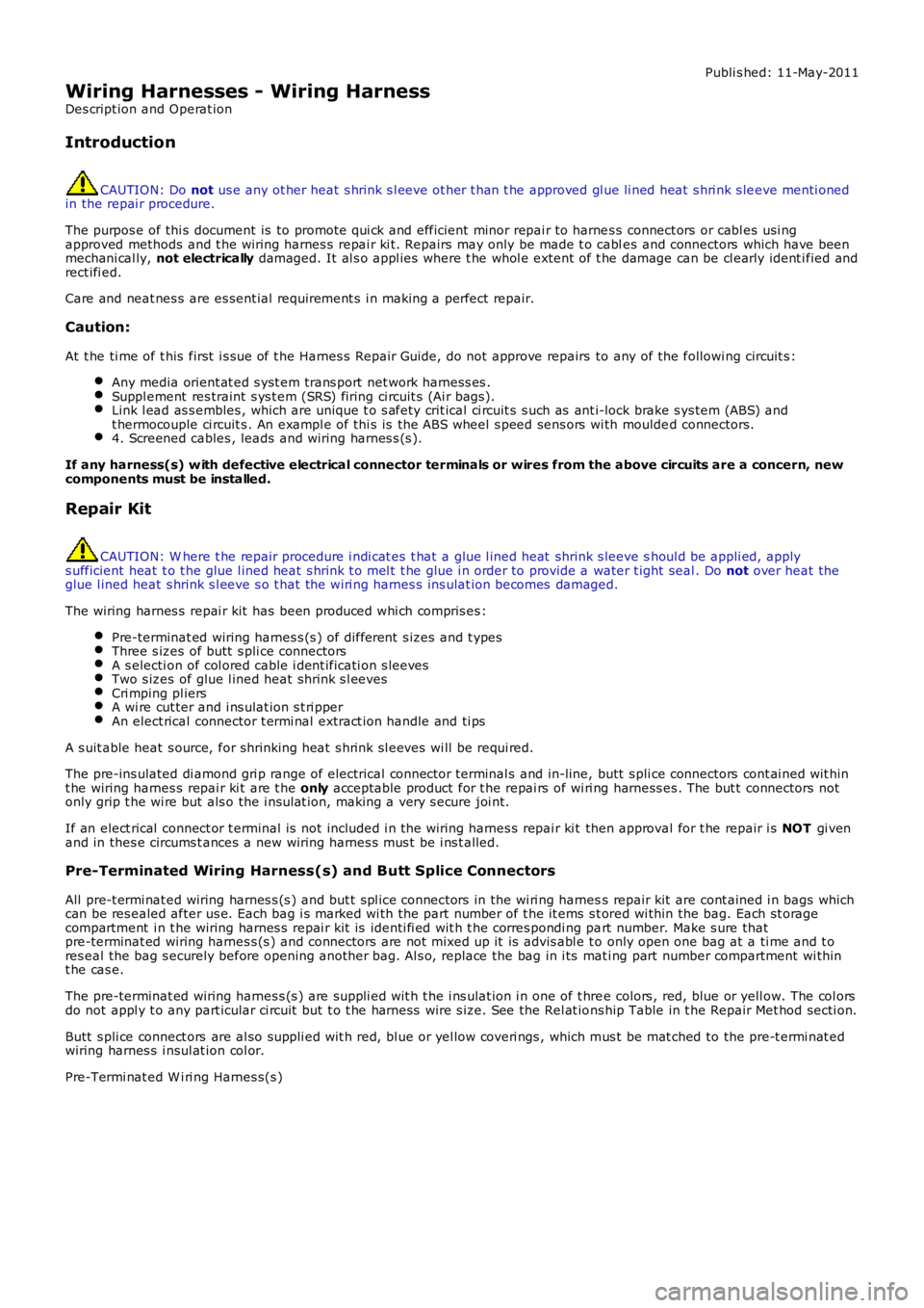
The wiring harnes s repai r kit has been produced whi ch compris es :
Pre-terminat ed wiring harnes s (s ) of different s izes and t ypesThree s izes of butt s pli ce connectorsA s electi on of col ored cable i dent ificati on s leevesTwo s izes of glue l ined heat s hrink s l eevesCri mping pl iersA wi re cut ter and i ns ulat ion s t ri pperAn elect rical connector t ermi nal extract ion handle and ti ps
A s uit able heat s ource, for shrinking heat s hrink sl eeves wi ll be requi red.
The pre-ins ulated di amond gri p range of electrical connect or terminal s and in-line, butt s pli ce connectors cont ai ned wit hint he wiring harnes s repai r ki t are t he only acceptable product for t he repai rs of wi ri ng harness es . The but t connectors notonly grip t he wi re but als o the i nsul at ion, making a very s ecure joi nt.
If an elect rical connect or t erminal is not included i n t he wiring harnes s repai r ki t then approval for t he repair i s NOT gi venand in thes e circums t ances a new wiring harnes s mus t be i ns t alled.
Pre-Terminated Wiring Harness(s) and Butt Splice Connectors
All pre-t ermi nat ed wiring harnes s (s ) and but t spl ice connectors in the wi ri ng harness repair kit are cont ained i n bags whichcan be res ealed after us e. Each bag i s marked wi th the part number of t he it ems s t ored wi thin the bag. Each st oragecompartment i n t he wiring harnes s repai r kit is identi fi ed wit h t he corres pondi ng part number. Make s ure thatpre-terminat ed wiring harnes s (s ) and connectors are not mixed up it is advis abl e t o only open one bag at a ti me and t ores eal the bag s ecurely before opening another bag. Al s o, replace the bag in i ts mati ng part number compartment wi thint he cas e.
The pre-terminat ed wiring harnes s (s ) are suppli ed wit h t he i ns ulat ion i n one of t hree colors , red, blue or yell ow. The col orsdo not appl y t o any part icular ci rcuit but t o t he harness wire s ize. See the Rel at ions hip Table in t he Repair Met hod secti on.
Butt s pli ce connect ors are al so suppli ed wit h red, bl ue or yel low coveri ngs , which mus t be mat ched to the pre-t ermi nat edwiring harnes s i nsul at ion col or.
Pre-Termi nat ed W i ri ng Harnes s(s )
Page 2014 of 3229
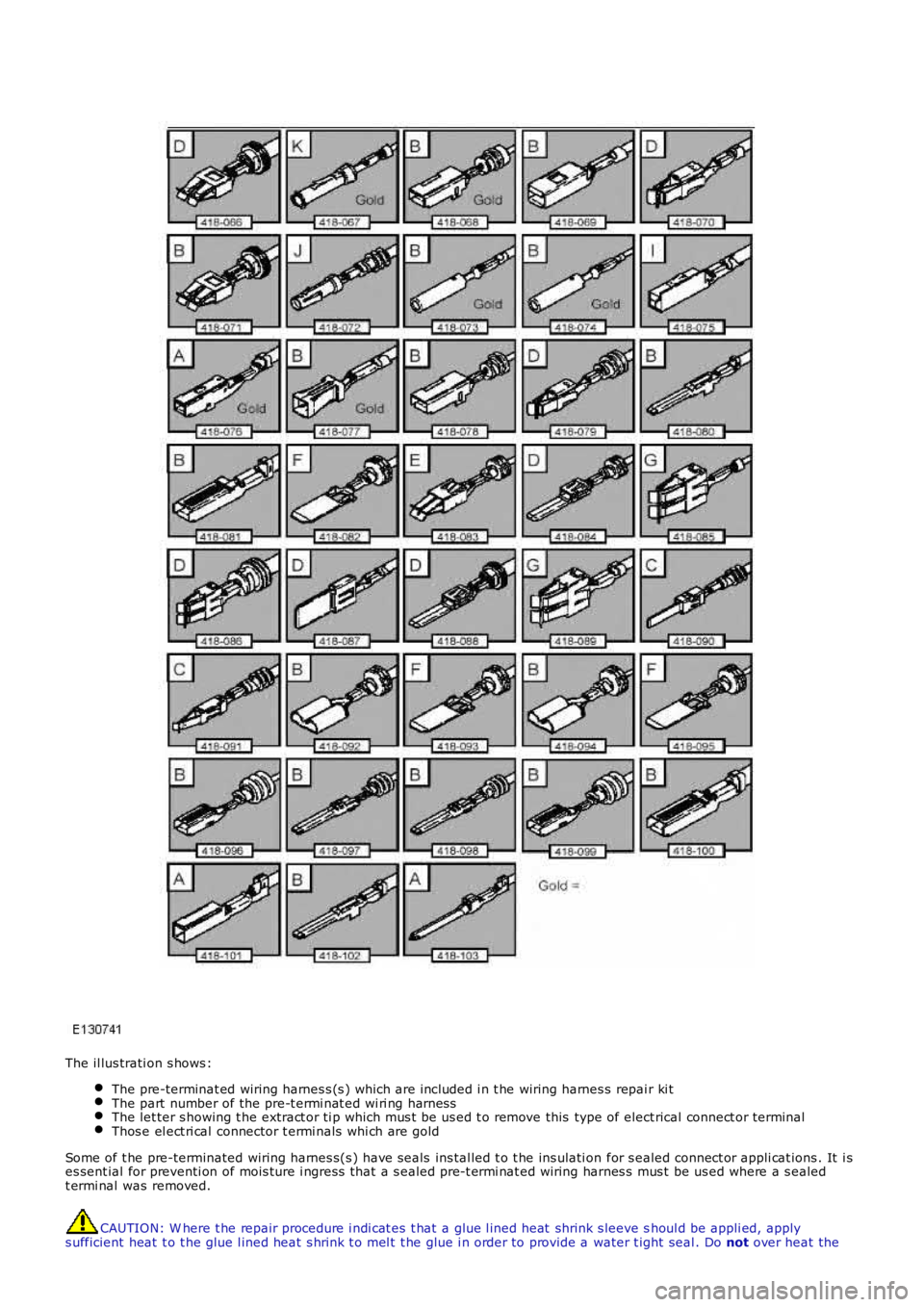
The il lus trati on s hows :
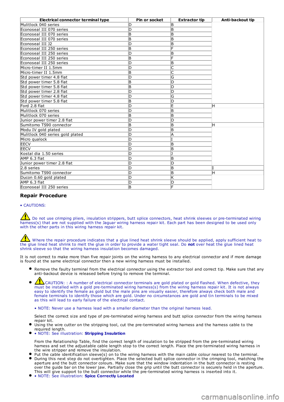
The pre-terminat ed wiring harnes s (s ) which are included i n t he wiring harnes s repai r ki tThe part number of the pre-t ermi nat ed wi ri ng harnessThe let ter s howing t he extract or ti p which mus t be us ed t o remove this type of electrical connect or terminalThos e el ect ri cal connector t ermi nals whi ch are gold
Some of t he pre-terminated wiring harnes s(s ) have seals ins tal led t o t he ins ulati on for s ealed connect or appli cat ions . It i ses sent ial for preventi on of mois ture i ngress that a s ealed pre-t ermi nat ed wiring harnes s mus t be us ed where a s ealedt ermi nal was removed.
CAUTION: W here t he repair procedure i ndi cat es t hat a glue l ined heat shrink s leeve shoul d be appli ed, applys ufficient heat t o t he glue l ined heat s hrink t o mel t t he glue i n order to provide a water t ight seal . Do not over heat the
Page 2015 of 3229
glue l ined heat s hrink s l eeve s o t hat the wiri ng harnes s ins ulat ion becomes damaged.
Two s izes of heat shrink s leeving are s uppl ied i n t he wiring harnes s repai r ki t. Each heat shrink s leeve cont ains a seal antglue. Thes e must be us ed when connect ing wi ri ng harness (s) or el ect ri cal connector termi nal (s ) at all t imes . The s mall erdiamet er heat s hri nk sl eeve is t o be us ed wi th the red and blue but t spl ice connectors and t he larger diamet er sl eeve wit ht he yel low but t s pl ice connect ors .
For eas e and s peed, s ome of t he pre-terminat ed wiring harnes s (s ) may al ready have the ins ul ati on part ly s t ripped at t hes plice end. If t he repai r requires ins ul ati on to be s tripped from the cable, refer to the Relat ions hip Table for the correctlength of ins ul ati on to be s tripped.
The Pre-Termi nat ed W i ri ng Harnes s(s ) il lus trati on shows t he elect rical connector t ermi nal t ype, t he part number of thepre-terminat ed wiring harnes s and t he let ter of t he ext ractor t ip which mus t be us ed to ext ract t he elect rical connect ort ermi nal from the connect or hous ing. Addi ti onal ly, t hos e el ect ri cal connector t ermi nal (s ) which are gold are i dent ified, allothers are t herefore, ti nned and not gold.
W i ri ng Harnes s Cabl e Ident ificati on Sleeves
A s electi on of col ored s leeves are cont ai ned in the wi ri ng harness repair kit for maint ai ning t he wi ring harnes s cableidenti fi cat ion on the pre-t ermi nat ed wi ri ng harness . Place t he correct col ored s l eeve(s ) over the pre-t ermi nat ed wi ri ngharnes s ins ulati on as near to the el ect ri cal connector as pos si ble wi th the main wi ri ng harness cable col or neares t t o t heelectrical connect or.
For example, i f the original wi ring harnes s cable color i s pink wi th a black t race put the pi nk wiring harnes s cableidenti fi cat ion s l eeve on the pre-t ermi nat ed wi ring harnes s firs t foll owed by a bl ack s l eeve, and s lide bot h along t he wi ri ngharnes s cabl e to the el ect ri cal connector t ermi nal.
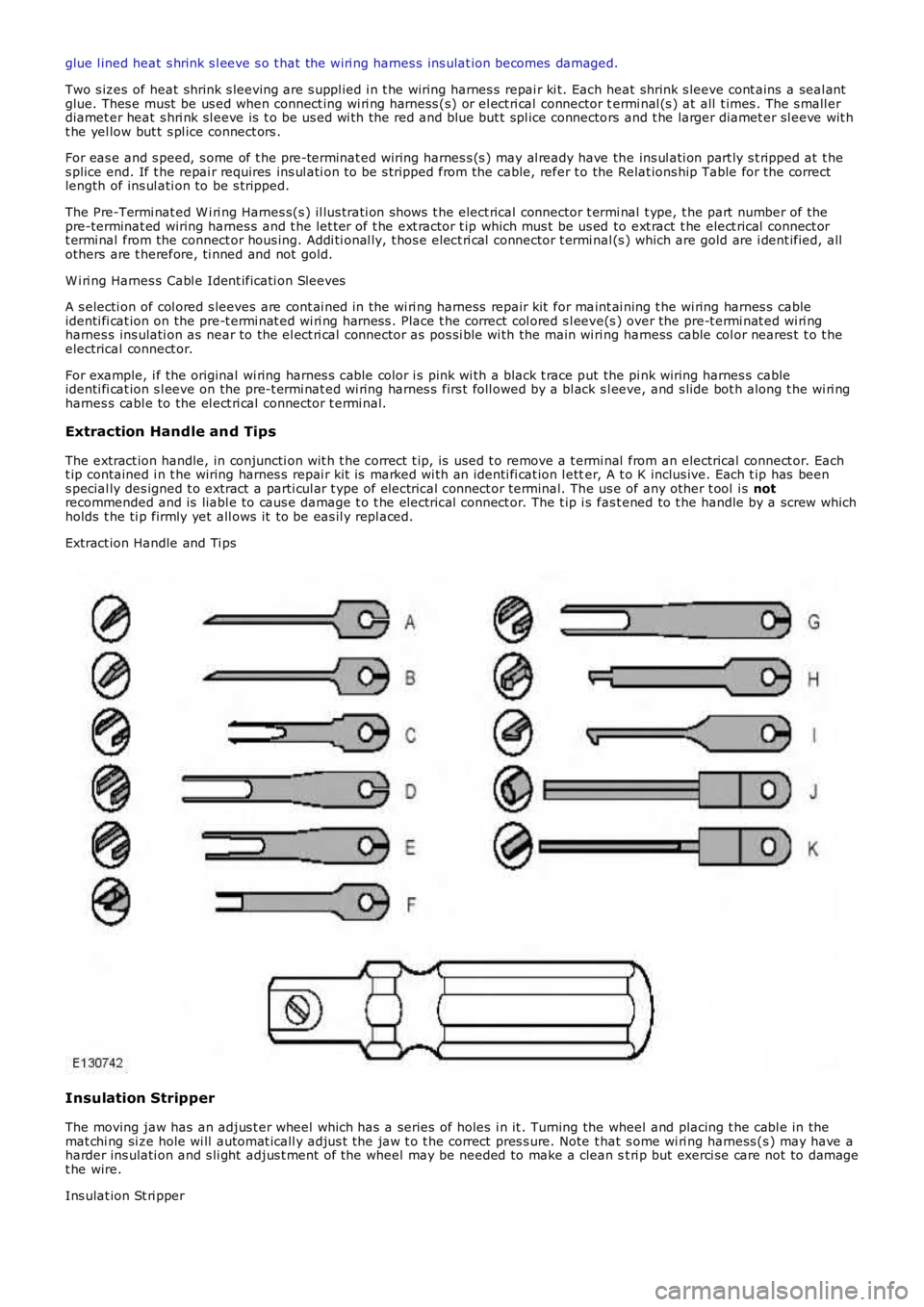
Extraction Handle and Tips
The extract ion handle, in conjuncti on wit h t he correct t ip, is used t o remove a t ermi nal from an electrical connect or. Eacht ip contained i n t he wiring harnes s repai r kit is marked wi th an identi fi cat ion l etter, A t o K inclus ive. Each t ip has beens pecial ly des igned t o extract a parti cul ar t ype of electrical connect or terminal. The us e of any other t ool i s notrecommended and is liabl e to caus e damage t o t he electrical connect or. The t ip i s fas t ened to t he handle by a screw whichholds t he ti p firmly yet all ows it to be eas il y repl aced.
Extract ion Handle and Ti ps
Insulation Stripper
The moving jaw has an adjus t er wheel which has a series of holes i n it . Turning the wheel and placing t he cabl e in themat chi ng si ze hole wi ll automat icall y adjus t the jaw t o t he correct pres s ure. Note that s ome wi ri ng harness (s ) may have aharder ins ulati on and s li ght adjus t ment of the wheel may be needed to make a clean st ri p but exerci se care not to damaget he wire.
Ins ulat ion St ri pper
Page 2016 of 3229
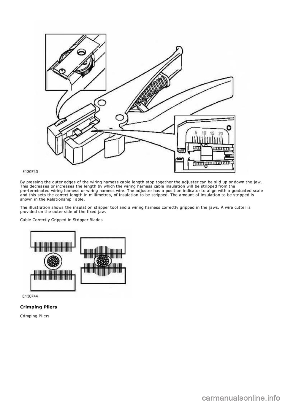
By pres s ing t he outer edges of the wi ri ng harnes s cabl e length st op t oget her the adjus t er can be s l id up or down t he jaw.This decreas es or i ncreases t he l engt h by which t he wi ri ng harness cable ins ul ati on wil l be s tripped from thepre-terminat ed wiring harnes s or wiring harnes s wi re. The adjus t er has a pos it ion indicator t o ali gn wit h a graduat ed s cal eand t hi s s ets t he correct l engt h i n mi lli metres , of i nsul at ion to be st ripped. The amount of ins ulati on t o be s tripped i ss hown in the Relat ions hip Table.
The il lus trati on s hows the i nsul at ion st ri pper t ool and a wiring harnes s correct ly gripped i n the jaws . A wi re cut ter isprovided on t he outer s ide of t he fixed jaw.
Cable Correctl y Gri pped in St ri pper Blades
Crimping Pliers
Cri mping Pl iers
Page 2017 of 3229
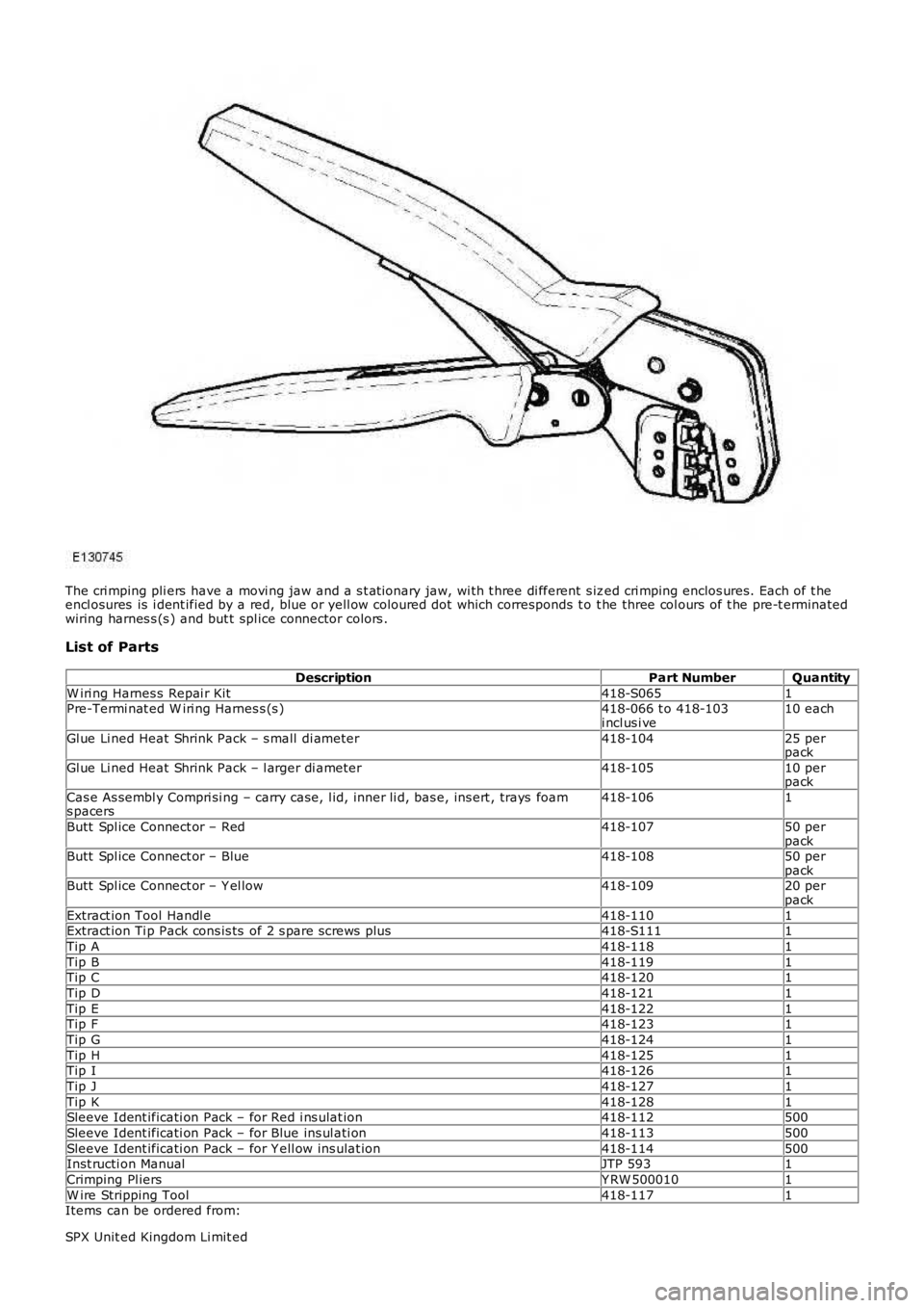
The cri mping pli ers have a movi ng jaw and a s t at ionary jaw, wi th t hree di fferent s ized cri mping enclos ures. Each of t heencl osures is i dent ified by a red, blue or yell ow coloured dot which corresponds t o t he three col ours of t he pre-t erminatedwiring harnes s (s ) and but t spl ice connector colors .
List of Parts
DescriptionPart NumberQuantity
W iri ng Harnes s Repai r Kit418-S0651Pre-Termi nat ed W iri ng Harnes s (s )418-066 t o 418-103i ncl us i ve10 each
Gl ue Li ned Heat Shrink Pack – s mall di ameter418-10425 perpack
Gl ue Li ned Heat Shrink Pack – l arger di ameter418-10510 perpack
Cas e As sembl y Compri si ng – carry case, l id, inner li d, bas e, ins ert , trays foams pacers418-1061
Butt Spl ice Connect or – Red418-10750 perpackButt Spl ice Connect or – Blue418-10850 perpackButt Spl ice Connect or – Y el low418-10920 perpack
Extract ion Tool Handl e418-1101Extract ion Ti p Pack cons is ts of 2 s pare s crews plus418-S1111
Tip A418-1181
Tip B418-1191Tip C418-1201
Tip D418-1211
Tip E418-1221Tip F418-1231
Tip G418-1241
Tip H418-1251Tip I418-1261
Tip J418-1271
Tip K418-1281Sleeve Ident ificati on Pack – for Red i ns ulat ion418-112500
Sleeve Ident ificati on Pack – for Blue ins ul ati on418-113500
Sleeve Ident ificati on Pack – for Y ell ow ins ulat ion418-114500Inst ructi on ManualJTP 5931
Crimping Pl iersY RW 5000101
W ire Stripping Tool418-1171Items can be ordered from:
SPX Unit ed Kingdom Li mit ed
Page 2018 of 3229
Ironst one W ay
Bri xwort h
Nort hant s
NN6 9UD
Unit ed Kingdom
Telephone: +44 (0) 1327 704461
Fax: +44 (0) 1327 706632
Repair Methods
CAUTION: Several different types and sizes of terminal may be found in a single electrical connector housing.
It is neces s ary to i dent ify:
The conductor (wire) si ze of the affected wiri ng harnes sThe electrical connect or range from which t he damaged wiri ng harnes s is to be removedThe t ermi nal t ype
Us e of the approved di agnos ti c tool wi ll greatl y as si s t in t he quick i dent ificati on of el ect ri cal connectors and faul ty pi nt ermi nal (s ).
Reference can als o be made to the vehicle Elect rical Gui des , held by Deal ers , to identi fy wi ri ng harness (s ) and el ect ri calconnector(s ).
By us ing t he Relat ionshi p Table, the wiring harnes s conductor (wire) si ze can be relat ed t o a s uit able pre-t ermi nat edwiring harnes s by t he color of the ins ul ati on. Al so, t he correct lengt h of ins ulati on t o be s tripped from the wiri ng harnes slead i s ident ifi ed.
Relationship Table
CABLE RANGESPLICEST RIP LENGT H
0.35 mm² t o 1.50 mm²RED6.00 t o 7.00 mm1.00 mm² t o 2.50 mm²BLUE6.00 t o 7.00 mm
4.00 mm² t o 6.00 mm²Y ELLO W9.00 t o 9.50 mm
Electrical Connector Terminal Extraction
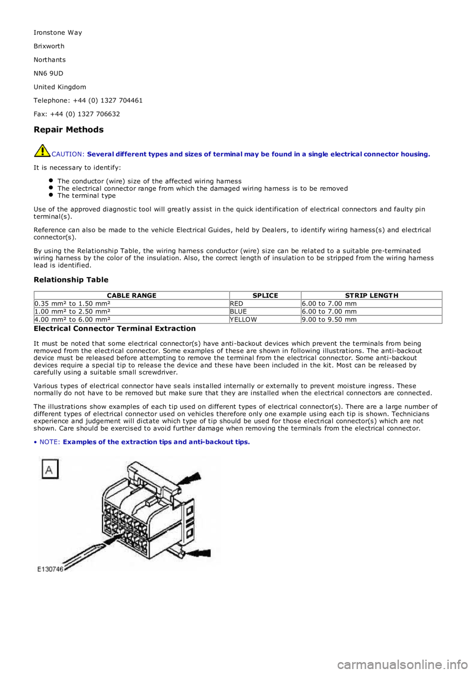
It must be not ed t hat s ome el ect ri cal connect or(s ) have anti -backout devices which prevent the t erminals from beingremoved from the el ect ri cal connect or. Some examples of t hes e are s hown in foll owing i llus t rat ions. The ant i-backoutdevi ce mus t be rel eas ed before att empt ing t o remove the t ermi nal from t he electrical connect or. Some ant i-backoutdevi ces require a s peci al t ip to releas e t he devi ce and thes e have been included in the kit . Mos t can be rel eas ed bycareful ly us ing a sui table small s crewdriver.
Vari ous types of el ect ri cal connect or have s eals i ns t alled internal ly or ext ernally to prevent moi st ure ingres s . Thes enormal ly do not have t o be removed but make s ure that t hey are i ns t alled when the elect ri cal connectors are connect ed.
The il lus trati ons show exampl es of each t ip us ed on di fferent types of electrical connect or(s). There are a l arge number ofdifferent t ypes of el ect ri cal connector us ed on vehi cles t herefore onl y one example us ing each t ip is s hown. Techniciansexperience and judgement wil l di ct ate which t ype of t ip should be used for t hos e el ect ri cal connector(s ) which are nots hown. Care s houl d be exercis ed t o avoi d further damage when removi ng the terminals from t he electrical connect or.
• NOTE: Examples of the extraction tips and anti-backout tips.
Page 2022 of 3229
Electrical connector terminal typePin or socketExtractor tipAnti-backout tip
Muli tl ock 040 seriesDB
Econos eal III 070 seriesDBEconos eal III 070 seriesBB
Econos eal III 070 seriesBB
Econos eal III J2DBEconos eal III 250 seriesBF
Econos eal III 250 seriesDB
Econos eal III 250 seriesBFEconos eal III 250 seriesDB
Mi cro-t imer II 1.5mmDC
Mi cro-t imer II 1.5mmBCSt d power t imer 4.8 flatDG
St d power t imer 5.8 flatBD
St d power t imer 5.8 flatBDSt d power t imer 2.8 flatDD
St d power t imer 4.8 flatDG
St d power t imer 5.8 flatBDFord 2.8 flatDEH
Muli tl ock 070 seriesDB
Muli tl ock 070 seriesBBJuni or power t imer 2.8 fl atDD
Sumit omo TS90 connect orBBH
Modu IV gold pl atedDBMuli tl ock 040 series gold pl atedDA
Mi cro qualockDI
EECVDBEECVDB
Kos tal dia 1.50 s eri esDJ
AMP 6.3 flatDBJuni or power t imer 2.8 fl atDD
2.8 s eriesDBI
Sumit omo TS90 connect orDBHDucon 0.60 gold platedDK
AMP 6.3 flatDD
Econos eal III 250 seriesBF
Repair Procedure
• CAUTIO NS:
Do not us e cri mping pl iers , i ns ulat ion s t ri ppers, but t s pl ice connectors , heat s hrink sl eeves or pre-t ermi nat ed wiringharnes s(s ) that are not s uppli ed wit h t he Jaguar wiring harnes s repai r ki t. Each part has been desi gned to be used onl ywit h t he ot her part s i n t hi s wi ring harnes s repai r kit .
W here t he repair procedure i ndicat es t hat a glue l ined heat shrink s leeve s houl d be appli ed, apply s uffici ent heat tot he glue l ined heat shrink t o mel t the gl ue in order to provi de a wat er ti ght s eal. Do not over heat t he glue lined heats hrink sl eeve s o that the wiring harnes s ins ulat ion becomes damaged.
It is not correct t o make more t han fi ve repair joi nts on the wiri ng harnes s to any elect rical connect or and i f more damageis found at the same electrical connect or then a new wiring harnes s mus t be i ns t alled.
Remove the fault y t ermi nal from the el ect ri cal connector us ing t he extract or tool and correct t ip. Make s ure t hat anyanti -backout devi ce is releas ed before trying t o remove the t ermi nal.
CAUTION: : A number of electrical connect or terminals are gold plated or gol d fl ashed. W hen defect ive, theymus t be ins t al led wit h a gold pre-t erminated wi ri ng harnes s(s ) from t he wi ring harnes s repai r kit . It i s not alwayseasy to ident ify t he femal e as gold but t he mal e pins are vis ually eas ier, therefore al ways check both male andfemal e t ermi nal s t o identi fy thos e which are gold. Under no ci rcums tances are gold and ti n t ermi nal s t o be mi xedas t hi s wi ll lead t o earl y fai lure of the el ect ri cal contact.
• NOTE: Never us e a harness lead wit h a smaller diamet er than t he ori ginal harness lead.
Select the correct s i ze and type of pre-terminat ed wiring harnes s and butt spl ice connector from the wi ri ng harnes srepair ki t.Us ing t he wi re cutt er on t he s tripping t ool, cut the pre-t ermi nat ed wi ring harnes s and t he harnes s cabl e t o t herequired lengt h.• NOTE: See il lus trati on: Stripping Insulation
From the Rel ati ons hip Table, find t he correct l engt h of ins ulat ion t o be s t ripped from the pre-t erminated wi ri ngharnes s and s et t he adjus t abl e cabl e lengt h s top t o t he correct l engt h. Pl ace the pre-t ermi nat ed wi ring harnes s i nt he wire s tripper and remove t he ins ulat ion.Put the cable ident ificati on s leeve(s ) on t o t he wiring harnes s wi th the mai n cabl e colour nearest t o t he t ermi nal .Duri ng thi s next s t ep do not overti ght en. Place the sel ect ed but t s pli ce connect or in t he cri mping t ool, mat chi ng theapert ure and t he butt connect or colours . Make s ure that t he window i ndent at ion in t he butt connect or is rest ingover t he guide bar on t he lower jaw. Parti ally cl ose the grip unt il t he but t connector i s s ecurel y held i n t he aperture.This wi ll give s upport t o t he but t connector whi le t he pre-terminat ed wiring harnes s i s ins ert ed int o i t.• NOTE: See il lus trati on: Spice Correctly Located