wiring LAND ROVER FRELANDER 2 2006 Repair Manual
[x] Cancel search | Manufacturer: LAND ROVER, Model Year: 2006, Model line: FRELANDER 2, Model: LAND ROVER FRELANDER 2 2006Pages: 3229, PDF Size: 78.5 MB
Page 22 of 3229
Do not t ouch t he glas s port ion of t he bulb.On no account s hould headlamps be s wi tched on wi th t he bulb removed from the headlamp.Bulb t es ti ng may only be carri ed out wit h the bul b ins t al led i n t he headl amp.Bulbs mus t be di spos ed of in accordance wit h the local aut horit y bye-laws .
Connectors and harnesses
The engi ne compart ment of a vehi cl e is a part icularl y host il e environment for el ect ri cal component s and connectors. Al waysobserve the foll owing:
Make s ure el ect ri cal ly related it ems are dry and oil free before di sconnect ing/connecti ng t es t equipment .Make s ure t hat dis connect ed mul ti pl ugs and s ens ors are prot ect ed from any pos s ibl e oil , coolant or other li qui dcont aminat ion. Any such contami nat ion could impair performance or l ead to component fail ure.Never force connectors apart or pull on t he wiring harnes s .Always make s ure locki ng t abs are dis engaged before di sconnect ing mul ti plugs etc. and make s ure that correctori ent ati on is achieved before connecti on.Make s ure t hat any protecti on covers, i nsul at ion et c. are replaced if dis t urbed.
Having confirmed t hat a component is fault y, carry out t he fol lowing:
Swit ch off t he ignit ion and di s connect t he batt ery.Remove the component and support t he dis connected harnes s .W hen replaci ng electrical components , keep oily hands away from electrical connect ions and make s ure that lockingt abs on connect ors are ful ly engaged.
Battery Disconnection/Connection
Always refer to the El ect ri cal Secti on of this manual - Bat tery Connecti on/Dis connecti on pri or t o at tempt ing t o connect ordis connect the bat tery.For addit ional informat ion, refer t o: Specificati ons (414-01 Bat t ery, Mount ing and Cables , Speci ficat ions).
Fuel Handling Precautions
The fol lowing informati on li s ts bas ic precauti ons which mus t be obs erved if fuel i s t o be handl ed s afely. It als o outl inesother areas of ris k which mus t not be i gnored. As t his informati on is is sued for basi c gui dance only, consul t your local Fi reDepart ment where any doubt as to personal and envi ronmental s afet y exi s ts - See al so Heal th and Safety Precaut ions .
General precaut ions
Always have t he correct type of fire ext inguis her cont aining Foam, CO2, Gas or powder acces s ible when handl ing ordrai ni ng fuel or dis mantl ing fuel s ys tems . Fire exti ngui shers mus t als o be l ocat ed in areas where fuel i s s tored.
Make s ure t hat sui table warning si gns are exhibit ed.
Keep all s ources of ignit ion wel l away from areas where fuel is bei ng handl ed.
Make s ure t hat any leadlamps are fl ameproof and kept clear of spi ll age.
• W ARNINGS:
Do not di sas s emble or reas s emble fuel sys tem components whils t vehicle is over a pit .
No one should be permi tt ed to repair component s as sociat ed wit h fuel wi thout fi rs t having s peci alis t t rai ni ng.
Always dis connect t he vehi cl e batt ery before carryi ng out dis ass embly, reas s embly or drai ning work on a fuel sys tem.
Fuel t ank and s ys t em drai ning
Drai ning mus t be carried out in accordance wit h t he procedures given in the relevant Fuel Syst em s ecti on of thi s manual .
• W ARNINGS:
Never drain fuel or work on a fuel sys t em whil e t he vehi cl e i s over a pi t. Ext raction or draining of fuel must becarri ed out in a well venti lated area.
Al ways at tach fuel vapor warning l abel s t o fuel t anks i mmediat ely after drai ni ng.
Contai ners us ed for s toring fuel must be cl early marked wit h t he cont ents and pl aced i n a safe s torage area whichmeets the requi rement s of the local authorit y.
CAUTION: Some fuel l ines are now i ns t alled wit h 'quick release' connectors. If a connect or i s damaged, no at t emptmus t be made t o repai r the connect or, a new fuel line and connect or(s ) as s embly must be ins tall ed.
Always release pipe cli ps full y before att empti ng t o dis connect fuel pipes.
Fuel tank repairs
CAUTION: No at tempt s hould be made to repair a pl ast ic fuel tank. If t he s truct ure of t he t ank is damaged, a new
Page 26 of 3229
• W ARNINGS:
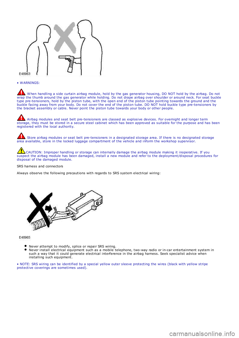
W hen handli ng a s ide curtain airbag modul e, hol d by t he gas generat or hous ing, DO NOT hold by the ai rbag. Do notwrap the t humb around t he gas generator whi le holdi ng. Do not drape airbag over s houl der or around neck. For s eat buckl et ype pre-t ens i oners, hold by the pi s ton t ube, wit h the open end of t he pis t on tube point ing t owards t he ground and t hebuckle facing away from your body. Do not cover the end of t he pis t on tube. DO NOT hold buckl e t ype pre-t ensi oners byt he bracket as s embl y or cabl e. Never point t he pis ton t ube t owards your body or other peopl e.
Ai rbag modules and s eat bel t pre-tens ioners are clas sed as expl os i ve devices . For overnight and l onger t erms torage, t hey must be st ored in a secure st eel cabinet which has been approved as s ui tabl e for t he purpos e and has beenregi st ered wi th the local authorit y.
St ore ai rbag modules or s eat bel t pre-tens ioners i n a des ignated s t orage area. If there is no des ignated st oragearea avail abl e, st ore in t he l ocked luggage compartment of t he vehi cl e and i nform t he works hop supervi sor.
CAUTION: Improper handl ing or s torage can i nternal ly damage t he airbag module maki ng it i noperat ive. If yous uspect the ai rbag module has been damaged, ins tal l a new module and refer t o t he depl oyment /di spos al procedures fordis posal of t he damaged modul e.
SRS harnes s and connectors
Always obs erve t he fol lowing precaut ions wit h regards to SRS s ys t em el ect ri cal wiring:
Never at tempt t o modi fy, s pl ice or repai r SRS wiring.Never i nst all electrical equi pment such as a mobi le telephone, t wo-way radio or i n-car ent ert ainment s yst em i ns uch a way t hat i t coul d generate el ect ri cal i nt erference in the ai rbag harnes s. Seek s peci alis t advice whenins t al li ng s uch equipment .
• NOTE: SRS wi ri ng can be identi fi ed by a s peci al yell ow outer s leeve prot ect ing the wi res (black wi th yell ow s t ri peprot ect ive coverings are s ometi mes used).
Page 27 of 3229
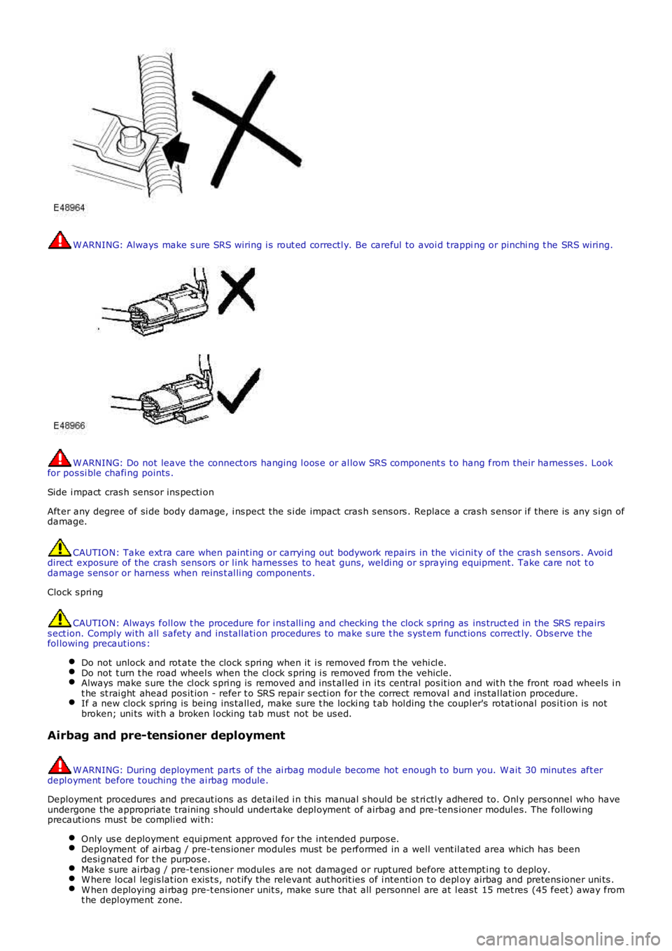
W ARNING: Always make s ure SRS wiring i s rout ed correctl y. Be careful to avoi d trapping or pinchi ng t he SRS wiring.
W ARNING: Do not leave the connect ors hanging l oos e or al low SRS component s t o hang from their harnes s es . Lookfor pos si ble chafi ng points .
Side i mpact cras h sens or ins pecti on
Aft er any degree of si de body damage, i ns pect the s i de impact cras h s ens ors . Replace a cras h s ens or i f there is any s i gn ofdamage.
CAUTION: Take ext ra care when paint ing or carryi ng out bodywork repairs in the vi ci ni ty of the cras h s ens ors . Avoi ddirect exposure of the crash sens ors or l ink harnes ses to heat guns, wel di ng or s praying equipment. Take care not t odamage s ens or or harness when reins t al li ng components .
Clock s pri ng
CAUTION: Always foll ow t he procedure for i ns t alli ng and checking t he clock s pring as ins truct ed in the SRS repairss ect ion. Comply wi th all s afety and ins tal lati on procedures to make s ure t he s yst em funct ions correct ly. Obs erve t hefol lowing precaut ions :
Do not unlock and rot ate the clock s pri ng when it i s removed from t he vehi cl e.Do not t urn t he road wheel s when the cl ock s pring i s removed from the vehicle.Always make s ure the cl ock s pri ng is removed and ins t al led i n i ts central pos it ion and wit h t he front road wheels i nt he st rai ght ahead pos it ion - refer t o SRS repair s ecti on for t he correct removal and ins tal lat ion procedure.If a new clock s pring is being ins tall ed, make sure t he locki ng t ab hol ding t he coupl er's rotat ional pos i ti on is notbroken; uni ts wit h a broken l ocking tab mus t not be us ed.
Airbag and pre-tensioner deployment
W ARNING: During deployment part s of the ai rbag modul e become hot enough to burn you. W ait 30 minut es aft erdepl oyment before t ouching the ai rbag module.
Deployment procedures and precaut ions as detai led i n thi s manual s hould be st ri ctl y adhered to. Onl y pers onnel who haveundergone the appropriate training s hould undert ake depl oyment of airbag and pre-tens ioner modul es. The followi ngprecaut ions mus t be compli ed wi th:
Only us e deployment equi pment approved for the intended purpos e.Deployment of ai rbag / pre-t ens ioner modules mus t be performed in a well vent il ated area which has beendesi gnat ed for t he purpos e.Make s ure ai rbag / pre-t ens ioner modules are not damaged or rupt ured before at tempt ing t o deploy.W here local legis lat ion exis t s, not ify the relevant aut horit ies of i ntenti on t o deploy airbag and pretens ioner uni ts .W hen deploying ai rbag pre-t ens ioner unit s, make s ure that all personnel are at l eas t 15 met res (45 feet ) away fromt he depl oyment zone.
Page 33 of 3229
Publi s hed: 11-May-2011
General Information - Health and Safety Precautions
Des cript ion and Operat ion
Introduction
Modern vehicles contai n many mat erial s and li qui ds which i f not handled wi th care can be hazardous to bot h pers onalheal th and the environment . Als o, many of t he procedures as s oci ated wit h vehi cl e maint enance and repai r involve physi calhazards or ot her ri sks t o healt h.
This s ubsect ion l is ts some of thes e hazardous operat ions and t he mat erial s and equi pment as s oci ated wi th them.Precaut ions necess ary to avoid thes e hazards are ident ified.
The li s t is not exhaus ti ve and all operat ions and procedures and the handli ng of materials , s houl d be carried out wi thheal th and s afety in mind.
Before usi ng any product the Mat eri al s Safet y Data Sheet s uppl ied by t he manufacturer or s uppli er s hould be cons ul ted.
W ARNING: Many liqui ds and ot her subs tances used in mot or vehi cl es are poi sonous and s houl d under nocircums t ances be consumed and should, as far as pos s ible, be kept from contact wit h t he s kin. Thes e l iquids ands ubs t ances i nclude acid, anti -freeze, brake fl uid, fuel , windscreen washer addi ti ves, l ubricants , refri gerant s and vari ousadhes ives .
Acids and Alkalis
For example - alkali s s uch as caus ti c soda us ed i n cleaning mat eri al s ; aci ds such as s ulphuri c aci d us ed in bat teries .
Both al kal is and acids are i rrit ant and corrosi ve t o the ski n, eyes , nos e and t hroat. They cause burns and can des t royordi nary prot ect ive clot hing.
Avoi d s plas hes to the s kin, eyes and cl othi ng. W ear s uit able prot ecti ve impervi ous apron, gl oves and goggles . Do notbreat h mi st s .
Make s ure acces s t o eye was h bott les , s hower and s oap are readil y avai lable for s pl ashi ng accident s.
Dis play Eye Hazard si gn.
Air Bags
Highly fl ammable, expl osi ve – obs erve No Smoking pol icy.
Us ed wit hin the vehicle as safety rest rai nts .
The inflat or contai ns a high-energy propel lant which, when ignit ed, produces a VERY HOT GAS (2500°C).
The gas inflator (generator) us ed i n air bags is Sodi um Azide. This mat eri al i s hermet icall y s eal ed in each ai r bag modul eand is compl et ely cons umed during depl oyment . No att empt s houl d be made t o open an ai r bag infl ator as t hi s wi ll lead t ot he ri sk of exposure t o Sodium Azi de. If a gas generator i s rupt ured, full prot ecti ve cl othing should be worn when deali ngwit h t he s pil lage.
Aft er normal depl oyment , gloves and s afety goggles s hould be worn during t he handl ing proces s.
Deployed air bags s hould be dis posed of i n a pl ast ic bag i n accordance wi th local regul ati ons at an approved chemicalwas te si te.
Follow ing any direct contact with Sodium Azide:
W as h affected areas thoroughly wi th water.SEEK IMMEDIAT E MEDICAL ASSIST ANCE.
Air Bags - Do' s
Do s t ore modules in an upright pos i ti on.Do keep modules dry.Do carry modules wi th the cover si de pointi ng away from the body.Do pl ace modul es wit h t hei r cover s ide upwards .Do careful ly ins pect modules for damage.Do s t and to one si de when connecti ng modules .Do make s ure all t es t equipment is properly cal ibrat ed and maint ained.Do was h hands aft er handli ng depl oyed ai r bags .
Air Bags - Do Not
Do Not s t ore highl y fl ammable materi al together wit h modul es or gas generat ors .Do Not s t ore gas generators at temperatures exceedi ng 80°C.Do Not s t ore modules ups ide down.Do Not at tempt t o open a gas generator hous ing.Do Not expos e gas generat ors t o open flame or s ources of heat .Do Not place anythi ng on top of a module cover.Do Not us e damaged modules .Do Not t ouch a fi red modul e or gas generat or for at leas t 10 mi nut es aft er fi ri ng.Do Not us e any electrical probes on t he wiring circui t.
Page 92 of 3229

DT CDescriptionPossible CauseAction
ins tal lati on of a new modul e/component
P0032-12HO2S Heater Control CircuitHigh (Bank 1, Sens or 1) -Circui t s hort to bat t ery
• NO TE: - Ci rcuit O_T_SHT1 -
Front heated oxygens ensor heater cont rolcircui t s hort ci rcuit t opowerFront heated oxygens ensor failure
Refer to the el ect ri cal circui t diagramsand check front heat ed oxygen s ensorheat er cont rol ci rcuit for short ci rcuit t opowerCheck and i ns t all a new front heatedoxygen s ens or as requi red. Refer to thewarrant y poli cy and procedures manual,or det ermi ne if any prior approvalprogramme is in operat ion, pri or t o t heins tal lati on of a new modul e/component
P0045-13Turbo charger/SuperchargerBoost Cont rol A Ci rcuit /Open - Circui t open
• NO TE: - Ci rcuit O_T_BPANEG -
Vari able geometryt urbocharger actuat or vanecircui t open ci rcuit
Refer to the el ect ri cal circui t diagramsand check variabl e geomet ryturbocharger act uator vane ci rcuit foropen ci rcuitCarry out t he pinpoint t est s as s oci at edwit h t his DTC us ing the manufact urerapproved di agnos ti c s ys t em
P0045-18Turbo charger/SuperchargerBoost Cont rol A Ci rcuit /Open - Circui t current belowt hreshol d
Power s tage t emperaturedependant currentl imi tat ion
Refer to the el ect ri cal circui t diagramsand check connecti ons are s ecure andwiring i ntegri tyCarry out t he pinpoint t est s as s oci at edwit h t his DTC us ing the manufact urerapproved di agnos ti c s ys t em
P0045-19Turbo charger/SuperchargerBoost Cont rol A Ci rcuit /Open - Circui t current abovet hreshol d
• NO TE: - Ci rcuit O_T_BPAPOS -
Actuat or-vane vari abl egeometry t urbocharger -Power s tage output 1(pos i ti ve) s hort circui t topowerTurbo charger actuatorpower s tage output 1circui t over current
• NOTE: Thi s DTC may be logged due t o batt eryvol tage. Check t he body cont rol module,informati on and entertainment module andnavi gat ion s ys tem module for relat ed DTC's . IfDTC's are logged s us pect generat or or bat terysupply vol tage faul t. Check and repair asrequired pri or t o di agnos ing t his DTC
Usi ng t he manufacturer approveddiagnos t ic s yst em perform t he (T urbo,exhaust gas recirculation and air pathdynamic test) rout ineRefer to the el ect ri cal circui t diagramsand check t he act uat or vane variablegeomet ry turbocharger ci rcuit -O_T_BPAPOS - For s hort circuit t o power
P0046-19Turbo charger/SuperchargerBoost Cont rol A Ci rcuitRange/Performance - Circui tcurrent above threshold
Power s tage exces st emperatureVari able geometryt urbocharger actuat or vanecircui t, s hort circui t toground, s hort circuit t opowerVari able geometryt urbocharger actuat or vanefailure
Refer to the el ect ri cal circui t diagramsand check t he variable geomet ryturbocharger act uator vane ci rcuit , forshort ci rcuit t o ground, s hort circuit t opowerCheck and i ns t all a new variablegeomet ry turbocharger act uat or vane asrequired. Refer t o t he warranty pol icyand procedures manual , or det ermi ne ifany prior approval programme is i noperati on, prior to the i nst all ati on of anew module/componentCarry out t he pinpoint t est s as s oci at edwit h t his DTC us ing the manufact urerapproved di agnos ti c s ys t em
P0047-11Turbo charger/SuperchargerBoost Cont rol A Ci rcuit Low -Circui t s hort to ground
• NO TE: - Ci rcuit O_T_BPAPOS -
Vari able geometryt urbocharger actuat or vanecircui t s hort ci rcuit t oground
Refer to the el ect ri cal circui t diagramsand check t he variable geomet ryturbocharger act uator vane ci rcuit , forshort ci rcuit t o groundCarry out t he pinpoint t est s as s oci at edwit h t his DTC us ing the manufact urerapproved di agnos ti c s ys t em
P0047-14Turbo charger/SuperchargerBoost Cont rol A Ci rcuit Low -Circui t s hort to ground oropen
• NO TE: - Ci rcuit O_T_BPANEG -
Vari able geometryt urbocharger actuat or vanecircui t s hort ci rcuit t oground, open ci rcuit
Refer to the el ect ri cal circui t diagramsand check t he variable geomet ryturbocharger act uator vane ci rcuit , forshort ci rcuit t o ground, open ci rcuitCarry out t he pinpoint t est s as s oci at edwit h t his DTC us ing the manufact urerapproved di agnos ti c s ys t em
P0047-18Turbo charger/SuperchargerBoost Cont rol A Ci rcuit Low -Circui t current belowt hreshol d
Power s tage currentl imi tat ionRefer to the el ect ri cal circui t diagramsand check connecti ons are s ecure andwiring i ntegri tyCarry out t he pinpoint t est s as s oci at edwit h t his DTC us ing the manufact urerapproved di agnos ti c s ys t em
Page 93 of 3229
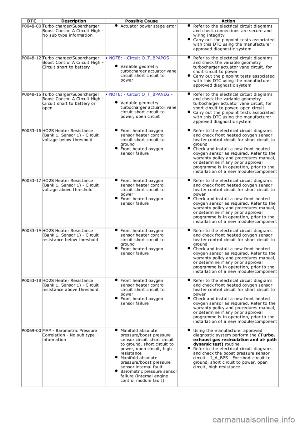
DT CDescriptionPossible CauseAction
P0048-00Turbo charger/SuperchargerBoost Cont rol A Ci rcuit High -No s ub t ype informati on
Actuat or power s tage errorRefer to the el ect ri cal circui t diagramsand check connecti ons are s ecure andwiring i ntegri tyCarry out t he pinpoint t est s as s oci at edwit h t his DTC us ing the manufact urerapproved di agnos ti c s ys t em
P0048-12Turbo charger/SuperchargerBoost Cont rol A Ci rcuit High -Circui t s hort to bat t ery
• NO TE: - Ci rcuit O_T_BPAPOS -
Vari able geometryt urbocharger actuat or vanecircui t s hort ci rcuit t opower
Refer to the el ect ri cal circui t diagramsand check t he variable geomet ryturbocharger act uator vane ci rcuit , forshort ci rcuit t o powerCarry out t he pinpoint t est s as s oci at edwit h t his DTC us ing the manufact urerapproved di agnos ti c s ys t em
P0048-15Turbo charger/SuperchargerBoost Cont rol A Ci rcuit High -Circui t s hort to bat t ery oropen
• NO TE: - Ci rcuit O_T_BPANEG -
Vari able geometryt urbocharger actuat or vanecircui t s hort ci rcuit t opower, open circui t
Refer to the el ect ri cal circui t diagramsand check t he variable geomet ryturbocharger act uator vane ci rcuit , forshort ci rcuit t o power, open circui tCarry out t he pinpoint t est s as s oci at edwit h t his DTC us ing the manufact urerapproved di agnos ti c s ys t em
P0053-16HO2S Heater Res is t ance(Bank 1, Sensor 1) - Ci rcuitvolt age bel ow t hres hol d
Front heated oxygens ensor heater cont rolcircui t s hort ci rcuit t ogroundFront heated oxygens ensor failure
Refer to the el ect ri cal circui t diagramsand check front heat ed oxygen s ensorheat er cont rol ci rcuit for short ci rcuit t ogroundCheck and i ns t all a new front heatedoxygen s ens or as requi red. Refer to thewarrant y poli cy and procedures manual,or det ermi ne if any prior approvalprogramme is in operat ion, pri or t o t heins tal lati on of a new modul e/component
P0053-17HO2S Heater Res is t ance(Bank 1, Sensor 1) - Ci rcuitvolt age above t hres hol d
Front heated oxygens ensor heater cont rolcircui t s hort ci rcuit t opowerFront heated oxygens ensor failure
Refer to the el ect ri cal circui t diagramsand check front heat ed oxygen s ensorheat er cont rol ci rcuit for short ci rcuit t opowerCheck and i ns t all a new front heatedoxygen s ens or as requi red. Refer to thewarrant y poli cy and procedures manual,or det ermi ne if any prior approvalprogramme is in operat ion, pri or t o t heins tal lati on of a new modul e/component
P0053-1AHO2S Heater Res is t ance(Bank 1, Sensor 1) - Ci rcuitres is t ance bel ow t hreshol d
Front heated oxygens ensor heater cont rolcircui t s hort ci rcuit t ogroundFront heated oxygens ensor failure
Refer to the el ect ri cal circui t diagramsand check front heat ed oxygen s ensorheat er cont rol ci rcuit for short ci rcuit t ogroundCheck and i ns t all a new front heatedoxygen s ens or as requi red. Refer to thewarrant y poli cy and procedures manual,or det ermi ne if any prior approvalprogramme is in operat ion, pri or t o t heins tal lati on of a new modul e/component
P0053-1BHO2S Heater Res is t ance(Bank 1, Sensor 1) - Ci rcuitres is t ance above t hres hol d
Front heated oxygens ensor heater cont rolcircui t s hort ci rcuit t opowerFront heated oxygens ensor failure
Refer to the el ect ri cal circui t diagramsand check front heat ed oxygen s ensorheat er cont rol ci rcuit for short ci rcuit t opowerCheck and i ns t all a new front heatedoxygen s ens or as requi red. Refer to thewarrant y poli cy and procedures manual,or det ermi ne if any prior approvalprogramme is in operat ion, pri or t o t heins tal lati on of a new modul e/component
P0069-00MAP - Barometric Pres s ureCorrelati on - No s ub t ypeinformat ion
Manifold abs olut epres s ure/boos t pres s ures ensor circui t s hort ci rcuitt o ground, s hort ci rcuit t opower, open circui t, highresi st anceManifold abs olut epres s ure/boos t pres s ures ensor i nt ernal faul tBaromet ri c pres s ure s ens orfailure (internal enginecontrol modul e fault )
Usi ng t he manufacturer approveddiagnos t ic s yst em perform t he (T urbo,exhaust gas recirculation and air pathdynamic test) rout ineRefer to the el ect ri cal circui t diagramsand check t he boos t pres s ure s ens orci rcuit - I_A_BPS - For s hort circui t toground, s hort circui t t o power, openci rcuit , high resi st ance
Page 96 of 3229
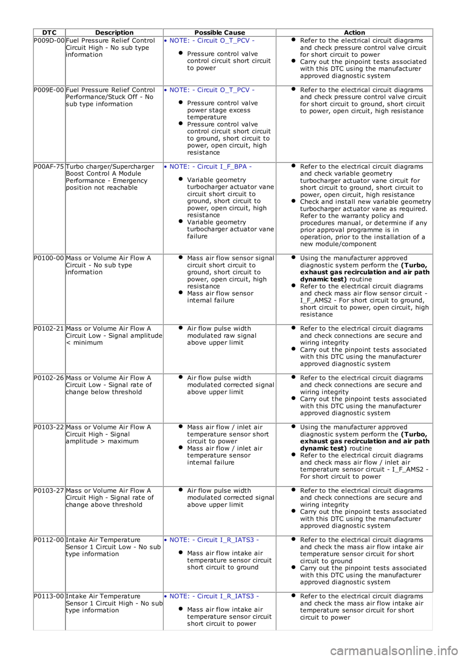
DT CDescriptionPossible CauseAction
P009D-00Fuel Pres s ure Rel ief ControlCircui t High - No s ub typeinformat ion
• NO TE: - Ci rcuit O_T_PCV -
Pres s ure control val vecontrol circui t s hort circuitt o power
Refer to the el ect ri cal circui t diagramsand check pres s ure control valve ci rcuitfor s hort circui t to powerCarry out t he pinpoint t est s as s oci at edwit h t his DTC us ing the manufact urerapproved di agnos ti c s ys t em
P009E-00Fuel Pres s ure Rel ief ControlPerformance/Stuck Off - Nos ub type i nformati on
• NO TE: - Ci rcuit O_T_PCV -
Pres s ure control val vepower s tage exces st emperaturePres s ure control val vecontrol circui t s hort circuitt o ground, s hort ci rcuit t opower, open circui t, highresi st ance
Refer to the el ect ri cal circui t diagramsand check pres s ure control valve ci rcuitfor s hort circui t to ground, s hort circui tto power, open ci rcuit , hi gh res i st ance
P00AF-75Turbo charger/SuperchargerBoost Cont rol A ModulePerformance - Emergencyposi ti on not reachable
• NO TE: - Ci rcuit I_F_BPA -
Vari able geometryt urbocharger actuat or vanecircui t s hort ci rcuit t oground, s hort circuit t opower, open circui t, highresi st anceVari able geometryt urbocharger actuat or vanefailure
Refer to the el ect ri cal circui t diagramsand check variabl e geomet ryturbocharger act uator vane ci rcuit forshort ci rcuit t o ground, s hort circuit t opower, open ci rcuit , high res i st anceCheck and i ns t all new vari abl e geometryturbocharger act uator vane as required.Refer to the warrant y policy andprocedures manual , or det ermi ne if anyprior approval programme is i noperati on, prior to the i nst all ati on of anew module/component
P0100-00Mas s or Vol ume Ai r Fl ow ACircui t - No s ub t ypeinformat ion
Mas s air flow sens or si gnalcircui t s hort ci rcuit t oground, s hort circuit t opower, open circui t, highresi st anceMas s air flow sens ori nt ernal fai lure
Usi ng t he manufacturer approveddiagnos t ic s yst em perform t he (T urbo,exhaust gas recirculation and air pathdynamic test) rout ineRefer to the el ect ri cal circui t diagramsand check mas s air flow sens or ci rcuit -I_F_AMS2 - For short ci rcuit t o ground,short ci rcuit t o power, open circui t, highres is t ance
P0102-21Mas s or Vol ume Ai r Fl ow ACircui t Low - Signal amplit ude< minimum
Ai r flow puls e wi dt hmodulat ed raw s ignalabove upper l imi t
Refer to the el ect ri cal circui t diagramsand check connecti ons are s ecure andwiring i ntegri tyCarry out t he pinpoint t est s as s oci at edwit h t his DTC us ing the manufact urerapproved di agnos ti c s ys t em
P0102-26Mas s or Vol ume Ai r Fl ow ACircui t Low - Signal rat e ofchange below threshold
Ai r flow puls e wi dt hmodulat ed correct ed si gnalabove upper l imi t
Refer to the el ect ri cal circui t diagramsand check connecti ons are s ecure andwiring i ntegri tyCarry out t he pinpoint t est s as s oci at edwit h t his DTC us ing the manufact urerapproved di agnos ti c s ys t em
P0103-22Mas s or Vol ume Ai r Fl ow ACircui t High - Si gnalampli tude > maximum
Mas s air flow / inlet ai rt emperature s ensor s hortcircui t to powerMas s air flow / inlet ai rt emperature s ensori nt ernal fai lure
Usi ng t he manufacturer approveddiagnos t ic s yst em perform t he (T urbo,exhaust gas recirculation and air pathdynamic test) rout ineRefer to the el ect ri cal circui t diagramsand check mas s air flow / inlet ai rtemperat ure sens or ci rcuit - I_F_AMS2 -For s hort circui t to power
P0103-27Mas s or Vol ume Ai r Fl ow ACircui t High - Si gnal rat e ofchange above threshold
Ai r flow puls e wi dt hmodulat ed correct ed si gnalabove upper l imi t
Refer to the el ect ri cal circui t diagramsand check connecti ons are s ecure andwiring i ntegri tyCarry out t he pinpoint t est s as s oci at edwit h t his DTC us ing the manufact urerapproved di agnos ti c s ys t em
P0112-00Int ake Air Temperat ureSens or 1 Ci rcuit Low - No s ubt ype i nformati on
• NO TE: - Ci rcuit I_R_IATS3 -
Mas s air flow int ake ai rt emperature s ensor circui ts hort circui t to ground
Refer to the el ect ri cal circui t diagramsand check t he mas s air flow i ntake airtemperat ure sens or ci rcuit for shortci rcuit t o groundCarry out t he pinpoint t est s as s oci at edwit h t his DTC us ing the manufact urerapproved di agnos ti c s ys t em
P0113-00Int ake Air Temperat ureSens or 1 Ci rcuit Hi gh - No s ubt ype i nformati on
• NO TE: - Ci rcuit I_R_IATS3 -
Mas s air flow int ake ai rt emperature s ensor circui ts hort circui t to power
Refer to the el ect ri cal circui t diagramsand check t he mas s air flow i ntake airtemperat ure sens or ci rcuit for shortci rcuit t o power
Page 294 of 3229
Inexperi enced off-road dri vers may benefi t from t he automat ic as s is tance of t he Terrai n Respons e s yst em and t he driverinformat ion. Experienced off-road drivers can s elect the specific programs for ext reme condit ions t o acces s cont rol over t hevehi cl e s yst ems (for example; accel erator pedal maps , t rans mis s ion s hift maps , traction s ett ings ) which are not access i bl eon vehicles wi thout Terrai n Res pons e.
Stop/St art Vehicl es - From 2010 MY
Acti vat ion of t he Terrai n Res pons e s peci al programs wi ll deact ivate the St op/St art syst em.
However, if Terrain Res pons e is acti vat ed when t he engi ne is shut down in a Stop/St art cycl e t he engi ne wil l aut omat ical lyres t art . If duri ng thi s event t he Stop/Start sys tem cannot detect the driver's occupancy, for example ei ther t he dri ver’ss afety bel t or door i s unlatched, the engine wi ll not res t art . The St op/St art s yst em will reques t t he driver t o depres s theclutch t o rest art t he engine. The dri ver wi ll be i nformed of t his by ‘RESTART REQUIRED PRESS CLUTCH’ being di spl ayed i nt he mes sage center.For addit ional informat ion, refer t o: Starti ng Sys t em (303-06C Starti ng Syst em - TD4 2.2L Di es el, Vehicles Bui lt From:01-03-2009, Descripti on and Operat ion).
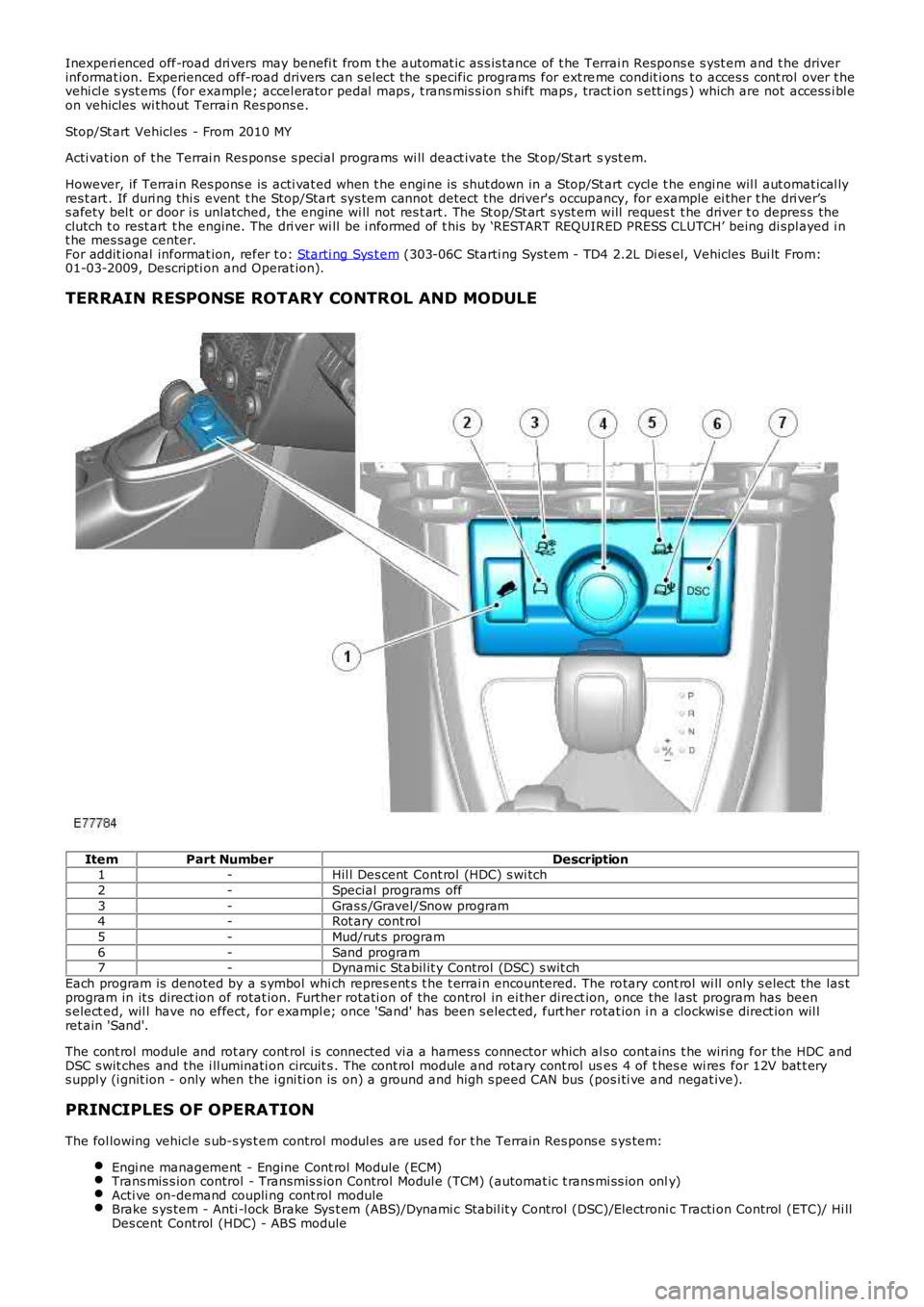
TERRAIN RESPONSE ROTARY CONTROL AND MODULE
ItemPart NumberDescription1-Hil l Des cent Cont rol (HDC) s wi tch
2-Special programs off
3-Gras s /Gravel/Snow program4-Rot ary cont rol
5-Mud/rut s program
6-Sand program7-Dynami c Stabil it y Control (DSC) s wit ch
Each program is denoted by a s ymbol whi ch repres ent s t he t errai n encountered. The rotary cont rol wi ll only s elect the las tprogram in it s direct ion of rotat ion. Further rot ati on of the control in ei ther direct ion, once the l ast program has beens elect ed, wil l have no effect, for exampl e; once 'Sand' has been s elect ed, furt her rotat ion i n a clockwis e direct ion wil lret ain 'Sand'.
The cont rol module and rot ary cont rol i s connected vi a a harnes s connector which al so cont ains t he wiring for the HDC andDSC s wit ches and the i ll uminati on circuit s . The cont rol module and rotary cont rol uses 4 of t hes e wi res for 12V bat t erys uppl y (i gnit ion - only when the i gni ti on is on) a ground and high s peed CAN bus (pos i ti ve and negat ive).
PRINCIPLES OF OPERATION
The fol lowing vehicl e s ub-s ys t em control modul es are us ed for t he Terrain Res pons e sys tem:
Engi ne management - Engine Cont rol Module (ECM)Trans mis s ion control - Transmis s ion Control Modul e (TCM) (automat ic t rans mi ss ion only)Acti ve on-demand coupli ng cont rol moduleBrake s ys tem - Anti -l ock Brake Sys t em (ABS)/Dynami c Stabil it y Control (DSC)/Electroni c Tracti on Control (ETC)/ Hi llDes cent Control (HDC) - ABS module
Page 409 of 3229
Publi s hed: 11-May-2011
Brake System - General Information - Brake System
Diagnosi s and Tes ti ng
Principle of Operation
For a detail ed descripti on of the brake s ys t em, refer t o t he rel evant Des cript ion and Operat ion secti on in the workshopmanual. REFER to:
Brake Syst em (206-00 Brake Sys t em - General Informat ion, Des cript ion and Operat ion),Front Dis c Brake (206-03 Front Di sc Brake, Des cri pt ion and Operati on),Rear Di sc Brake (206-04 Rear Di s c Brake, Des cri pti on and Operati on),Parking Brake (206-05 Parki ng Brake and Actuat ion, Descri pti on and Operat ion),Hydraul ic Brake Act uati on (206-06 Hydraul ic Brake Act uati on, Des cript ion and Operat ion),Brake Boost er (206-07 Power Brake Act uat ion, Des cript ion and Operat ion).
Inspection and Verification
1. Verify t he cus t omer concern.1.
2. Vis ually ins pect for obvious s igns of damage and s ys t em i ntegri ty.2.
Visual Inspection
MechanicalElectricalBrake mast er cyl inderBrake cali per pi st on(s )Brake di scsW heel bearingsBrake padsPower brake boos t erVacuum pumpBrake pedal li nkageBrake boos ter vacuum hos eTires
Damaged or corroded wiring harnes sBrake mas ter cyli nder fluid level s wi tch
3. If an obvious cause for an obs erved or report ed concern is found, correct t he caus e (if pos s ible) beforeproceeding t o t he next s t ep.3.
4. If t he caus e is not vis ually evi dent , verify t he concern and refer t o t he Sympt om Chart.4.
Road Test
Carry out a road tes t to compare act ual vehicl e braking performance wi th the performance s t andards expected by t hedri ver. The abi li ty of t he t est driver to make val id compari s ons and det ect performance defi cienci es wil l depend onexperience.
The dri ver s hould have a t horough knowl edge of brake s ys t em operat ion and accept ed general performance guideli nes tomake good comparis ons and detect performance concerns .
An experienced brake t echnician will al ways es t abl is h a route that wi ll be us ed for all brake di agnos is road t es t s . Theroads s elected will be reasonably s moot h and level. Gravel or bumpy roads are not sui table because the s urface does notall ow t he ti res t o grip t he road equall y. Crowned roads s houl d be avoided becaus e of t he large amount of wei ght s hifted tot he low set of wheels on t his type of road. Once the route is es tabl is hed and cons ist ent ly us ed, the road s urface vari ablecan be eli minat ed from t he t es t resul ts .
Before a road tes t, obt ain a compl et e des cript ion of t he cus t omer concerns or s uspected condit ion. From t he des cript ion,t he techni cian's experience wi ll all ow t he techni cian t o mat ch pos s ibl e caus es wi th s ympt oms. Certai n components wil l bet agged as pos si ble s us pect s whil e others wil l be eli minated by the evidence. More i mport ant ly, t he cus t omer des cri pt ioncan reveal uns afe condit ions which s hould be checked or correct ed before the road t est . The descri pti on wil l als o help formt he bas i c approach t o t he road tes t by narrowi ng t he concern t o s peci fi c components , vehicle s peed or condit ions .
Begin t he road tes t wit h a general brake performance check. Keepi ng t he des cri pti on of the concern in mind, t est t hebrakes at different vehicle s peeds usi ng both light and heavy pedal pres s ure.
If the concern becomes evident duri ng thi s check, verify it fit s t he descri pti on given before the road t est . If t he concern isnot evi dent , att empt to dupl icate t he condi ti on us ing t he informat ion from the des cri pt ion.
If a concern exi st s , refer t o t he Symptom Chart.
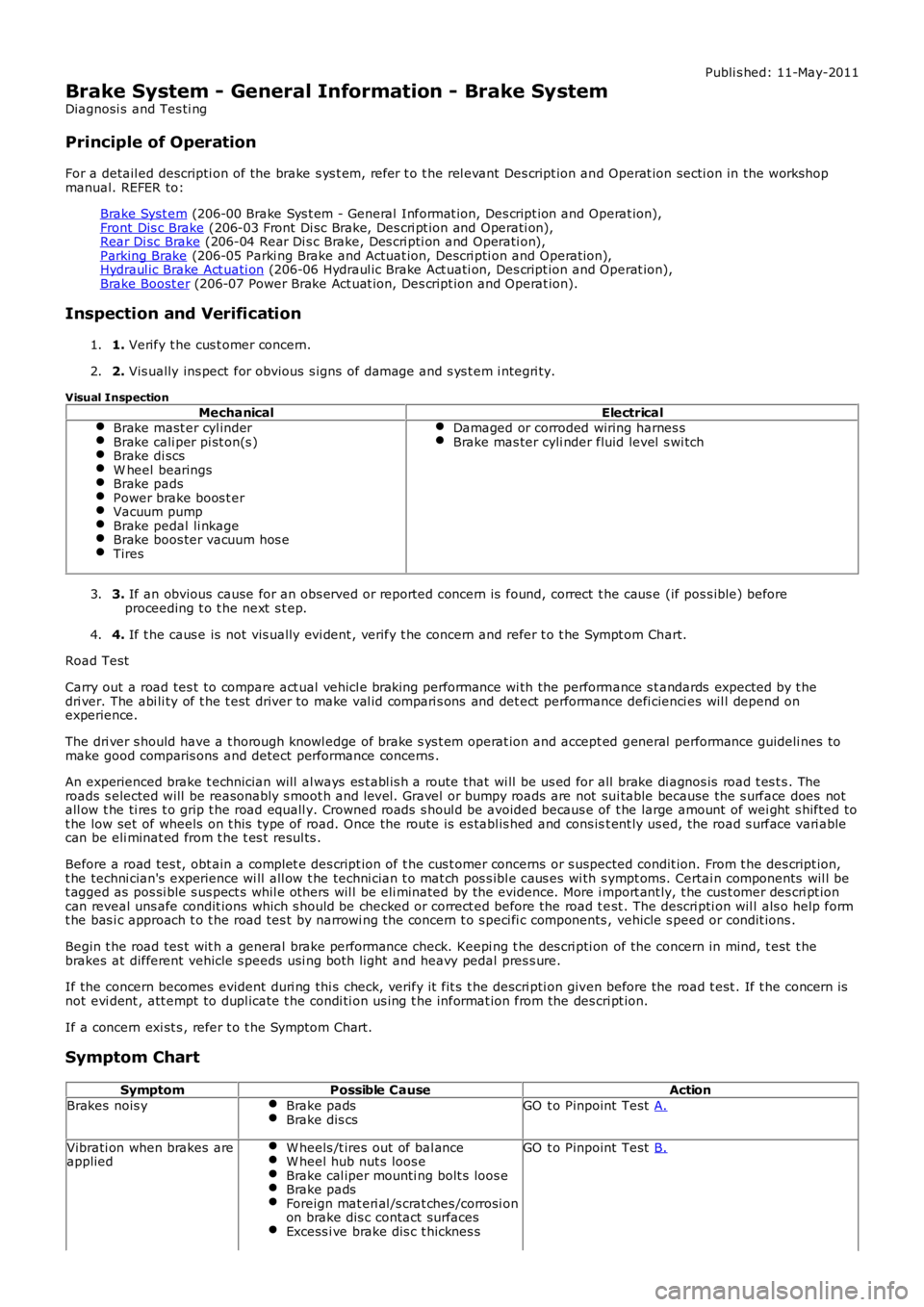
Symptom Chart
SymptomPossible CauseAction
Brakes nois yBrake padsBrake dis csGO t o Pinpoint Test A.
Vibrati on when brakes areappliedW heels /t ires out of bal anceW heel hub nut s loos eBrake cal iper mounti ng bolt s loos eBrake padsForeign mat eri al /s crat ches /corrosi onon brake dis c contact surfacesExcess i ve brake dis c t hicknes s
GO t o Pinpoint Test B.
Page 577 of 3229
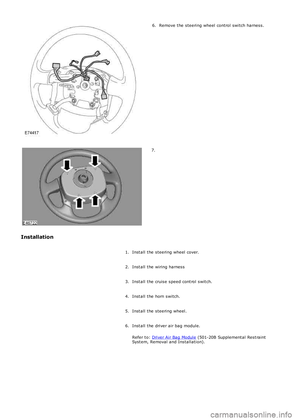
Remove t he s teeri ng wheel control swi tch harnes s .6.
7.
Installation
Inst all t he s teeri ng wheel cover.1.
Inst all t he wiring harnes s2.
Inst all t he cruis e s peed cont rol s wit ch.3.
Inst all t he horn s wi tch.4.
Inst all t he s teeri ng wheel .5.
Inst all t he dri ver air bag modul e.
Refer t o: Dri ver Ai r Bag Modul e (501-20B Supplement al Res t raintSyst em, Removal and Ins tall ati on).
6.