wiring LAND ROVER FRELANDER 2 2006 Owner's Manual
[x] Cancel search | Manufacturer: LAND ROVER, Model Year: 2006, Model line: FRELANDER 2, Model: LAND ROVER FRELANDER 2 2006Pages: 3229, PDF Size: 78.5 MB
Page 905 of 3229
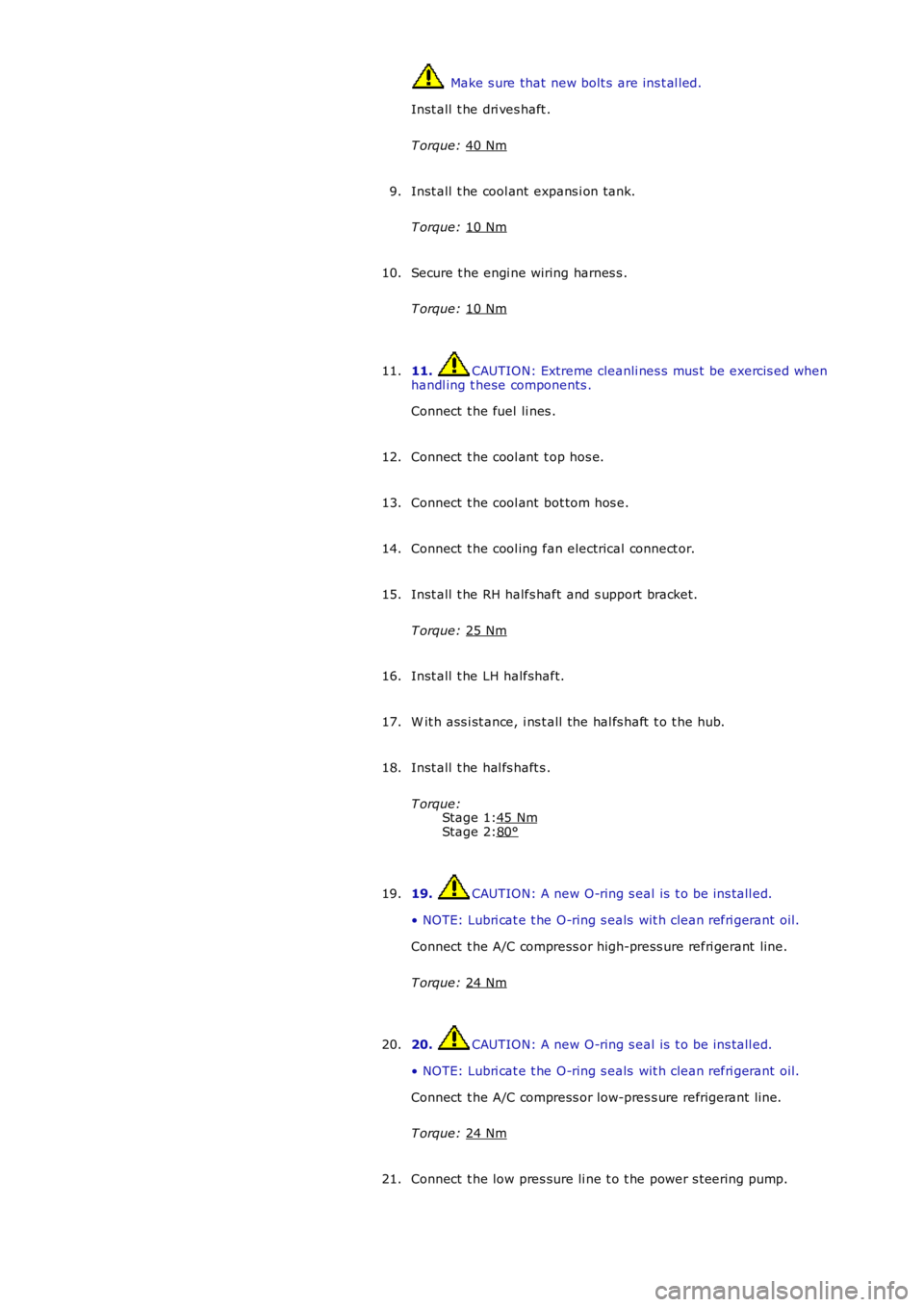
Stage 1:
Stage 2: Make s ure that new bolt s are ins t al led.
Inst all t he dri ves haft .
T orque: 40 Nm Inst all t he cool ant expans i on tank.
T orque: 10 Nm 9.
Secure t he engi ne wiring harnes s .
T orque: 10 Nm 10.
11. CAUTION: Extreme cleanli nes s mus t be exercis ed when
handl ing t hese components .
Connect t he fuel li nes .
11.
Connect t he cool ant t op hos e.
12.
Connect t he cool ant bot tom hos e.
13.
Connect t he cool ing fan electrical connect or.
14.
Inst all t he RH halfs haft and s upport bracket.
T orque: 25 Nm 15.
Inst all t he LH halfshaft.
16.
W it h ass i st ance, i ns t all the hal fs haft t o t he hub.
17.
Inst all t he hal fs haft s .
T orque: 45 Nm 80°18.
19. CAUTION: A new O-ring s eal is t o be ins tall ed.
• NOTE: Lubri cat e t he O-ring s eals wit h clean refri gerant oil.
Connect t he A/C compress or high-press ure refri gerant line.
T orque: 24 Nm 19.
20. CAUTION: A new O-ring s eal is t o be ins tall ed.
• NOTE: Lubri cat e t he O-ring s eals wit h clean refri gerant oil.
Connect t he A/C compress or low-pres s ure refrigerant li ne.
T orque: 24 Nm 20.
Connect t he low pres sure li ne t o t he power s t eering pump.
21.
Page 931 of 3229
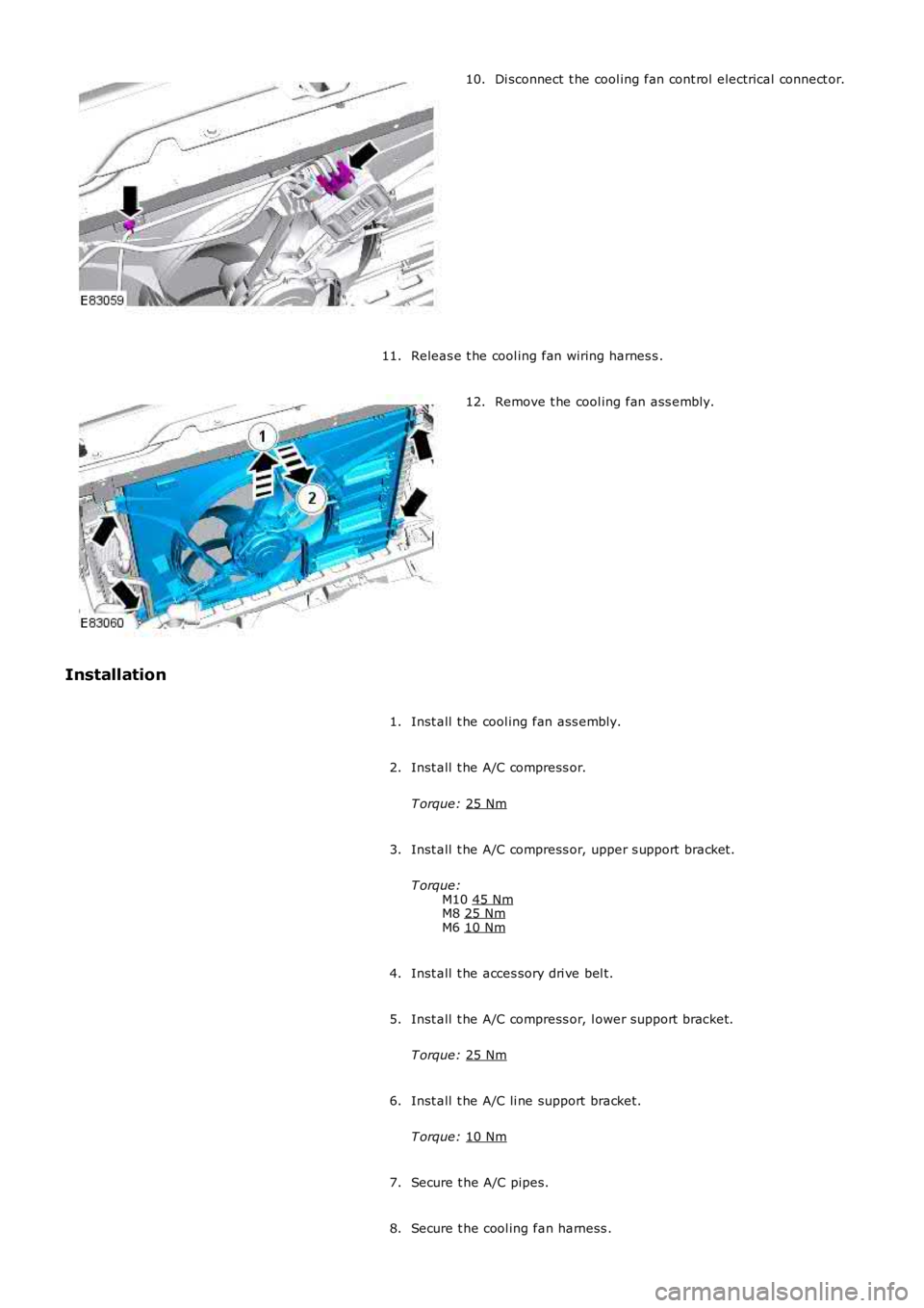
Di sconnect t he cool ing fan cont rol electrical connect or.
10.
Releas e t he cool ing fan wiring harnes s .
11. Remove t he cool ing fan ass embly.
12.
Installation Inst all t he cool ing fan ass embly.
1.
Inst all t he A/C compress or.
T orque: 25 Nm 2.
Inst all t he A/C compress or, upper s upport bracket.
T orque: M10 45 Nm M8
25 Nm M6
10 Nm 3.
Inst all t he acces sory dri ve bel t.
4.
Inst all t he A/C compress or, l ower support bracket.
T orque: 25 Nm 5.
Inst all t he A/C li ne support bracket.
T orque: 10 Nm 6.
Secure t he A/C pipes.
7.
Secure t he cool ing fan harness .
8.
Page 963 of 3229
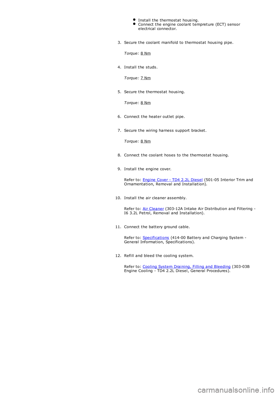
Inst all t he thermost at hous i ng.
Connect t he engi ne cool ant t empret ure (ECT) s ens or
electrical connect or. Secure t he cool ant mani fold to thermost at hous ing pi pe.
T orque: 8 Nm 3.
Inst all t he s tuds .
T orque: 7 Nm 4.
Secure t he thermost at hous i ng.
T orque: 8 Nm 5.
Connect t he heat er out let pi pe.
6.
Secure t he wiring harnes s s upport bracket .
T orque: 8 Nm 7.
Connect t he cool ant hos es to the thermos t at hous ing.
8.
Inst all t he engi ne cover.
Refer t o: Engi ne Cover - TD4 2.2L Dies el (501-05 Interior Tri m and
Ornament ati on, Removal and Ins tal lat ion).
9.
Inst all t he air cleaner as s embly.
Refer t o: Air Cleaner (303-12A Intake Ai r Dis tribut ion and Fil tering -
I6 3.2L Pet rol, Removal and Ins t al lat ion).
10.
Connect t he batt ery ground cable.
Refer t o: Specificati ons (414-00 Bat tery and Charging Sys tem -
General Informat ion, Specificati ons).
11.
Refi ll and bleed t he cool ing s ys tem.
Refer t o: Cool ing Sys tem Drai ni ng, Fi lli ng and Bleeding (303-03B
Engine Cooli ng - TD4 2.2L Di esel , General Procedures ).
12.
Page 1131 of 3229
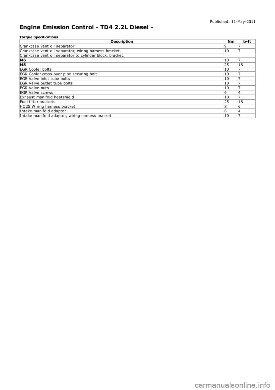
Publi s hed: 11-May-2011
Engine Emission Control - TD4 2.2L Diesel -
Torque SpecificationsDescriptionNmlb-ft
Crankcas e vent oil s eparator97
Crankcas e vent oil s eparator, wiring harnes s bracket.107Crankcas e vent oil s eparator t o cylinder block, bracket.
M6107
M82518EGR Cooler bolt s107
EGR Cooler cros s -over pipe s ecuring bolt107
EGR Val ve inlet t ube bol ts107EGR Val ve out let t ube bol ts107
EGR Val ve nut s107
EGR Val ve screws64Exhaus t manifold heat shi el d107
Fuel fil ter brackets2518
HO2S W iring harnes s bracket86Intake manifold adaptor64
Intake manifold adaptor, wiring harnes s bracket107
Page 1254 of 3229
Publi s hed: 11-May-2011
Electronic Engine Controls - TD4 2.2L Diesel - Crankshaft Position (CKP)
Sensor
Removal and Inst all ati on
Removal
• NOTE: Removal s t eps in t his procedure may cont ain i nst all ati on det ail s.
1. W ARNING: Make sure t o s upport the vehicle wit h axle
s tands .
Rais e and s upport t he vehi cl e.
1.
Remove t he front wheel .
Refer t o: W heel and Ti re (204-04 W heel s and Tires, Removal and
Inst all at ion).
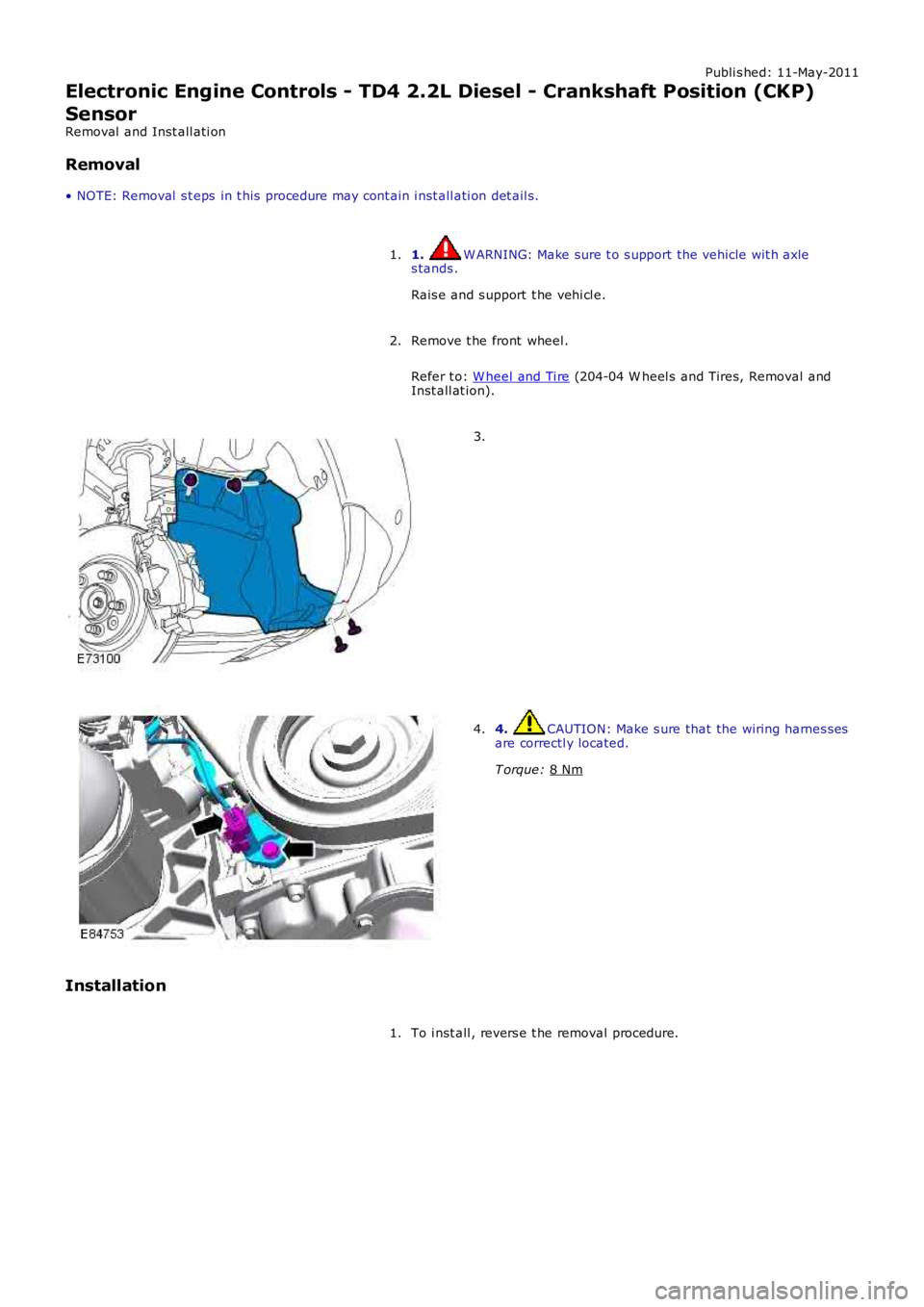
2. 3.
4. CAUTION: Make s ure that the wiring harnes s es
are correctl y located.
T orque: 8 Nm 4.
Installation To i nst all , revers e t he removal procedure.
1.
Page 1323 of 3229
Publi s hed: 11-May-2011
Automatic Transmission/Transaxle - Main Control Valve Body
Removal and Inst all ati on
Removal
Remove t he cover and dis connect the bat tery ground cabl e.
Refer t o: Specificati ons (414-00 Bat tery and Charging Sys tem -General Informat ion, Specificati ons).
1.
2. W ARNING: Make sure t o s upport the vehicle wit h axles tands .
Rais e and s upport t he vehi cl e.
2.
Remove t he oil pan.
Refer t o: Transmis s ion Flui d Pan (307-01 Automat icTrans mi ss ion/Transaxle, Removal and Ins tal lati on).
3.
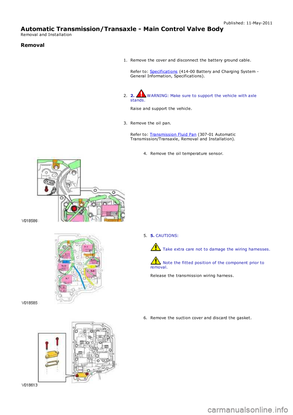
Remove the oi l temperat ure sens or.4.
5. CAUTIONS:
Take ext ra care not t o damage the wiring harnes ses .
Not e the fi tt ed posi ti on of the component prior t oremoval.
Release the trans mi ss i on wiring harnes s .
5.
Remove the sucti on cover and dis card t he gas ket .6.
Page 1324 of 3229
7.
8.
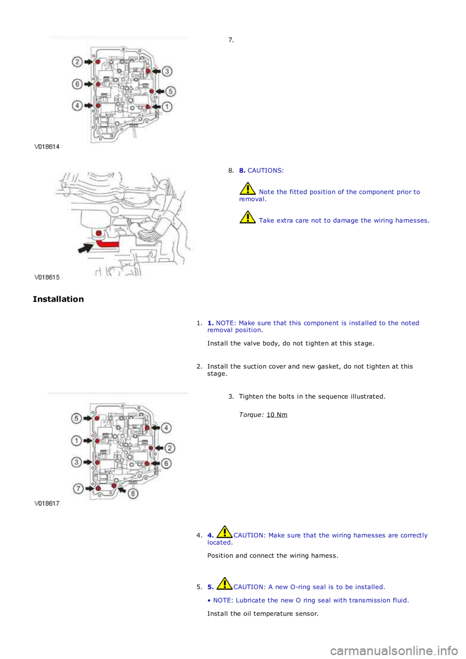
CAUTIONS: Not e the fi tt ed posi ti on of the component prior t o
removal. Take ext ra care not t o damage the wiring harnes ses .
8.
Installation 1. NOTE: Make s ure t hat this component is i nst all ed to the not ed
removal posi ti on.
Inst all t he val ve body, do not t ighten at t his s t age.
1.
Inst all t he s uct ion cover and new gas ket, do not t ighten at t his
s tage.
2. Tighten the bolt s i n t he sequence ill ust rat ed.
T orque: 10 Nm 3.
4. CAUTION: Make s ure that the wiring harnes s es are correct ly
l ocated.
Pos it ion and connect the wiring harnes s .
4.
5. CAUTION: A new O-ring seal is to be ins tall ed.
• NOTE: Lubri cat e t he new O ring seal wit h t rans mi ss ion fl ui d.
Inst all t he oil t emperature s ens or.
5.
Page 1541 of 3229
Onl y t ighten t he nut fi nger t ight at t hi s s tage.
Inst all t he cat alys t.
Inst all t he DPF.
Refer t o: Dies el Parti cul at e Fil ter (DPF) (309-00B Exhaus t Sys tem -
TD4 2.2L Dies el, Removal and Inst all ati on).
5.
Tight en the nut clampi ng the cat alyst to t he t urbocharger.
T orque: 10 Nm 6.
Inst all t he engi ne undershi eld.
Refer t o: Engi ne Unders hi eld (501-02 Front End Body Panel s ,
Removal and Ins tall ati on).
7.
Connect t he heat ed oxygen s ens or (H02S) el ect ri cal connect or.
8.
9. CAUTION: Make s ure that the wiring harnes s es are correct ly
rout ed.
Connect t he temperature s ens or electrical connect or.
9.
Inst all t he engi ne cover.
Refer t o: Engi ne Cover - TD4 2.2L Dies el (501-05 Interior Tri m and
Ornament ati on, Removal and Ins tal lat ion).
10.
Page 1547 of 3229
Inst all t he pres sure s ensi ng pipes .
T orque: 25 Nm 3.
Inst all t he pipe clamp.
T orque: 10 Nm 4.
5. W ARNING: Make sure t hat new nut s are ins tal led.
CAUTION: Make s ure that t he mati ng faces are cl ean and free
of foreign mat eri al .
• NOTE: Inst all a new gas ket.
Inst all t he dies el parti culat e fil ter.
T orque: 25 Nm 5.
6. CAUTION: Make s ure that the wiring harnes s es are correct ly
l ocated.
Connect t he temperature s ens or electrical connect or.
6.
7. CAUTIONS: Make s ure that t he ins tal lat ion marks are al igned.
Secure t he high press ure hose wit h a cli p.
Connect t he s ens or hoses .
7.
Inst all t he exhaus t sys t em.
Refer t o: Exhaus t Sys t em (309-00A Exhaus t Sys t em - I6 3.2L Pet rol ,
Removal and Ins tall ati on).
8.
Inst all t he engi ne undershi eld.
Refer t o: Engi ne Unders hi eld (501-02 Front End Body Panel s ,
Removal and Ins tall ati on).
9.
Page 1608 of 3229
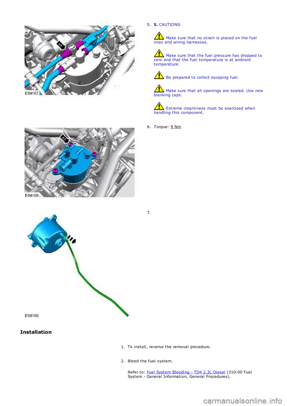
5.
CAUTIONS: Make s ure that no s t rain is pl aced on t he fuel
l ines and wiring harnes s es. Make s ure that t he fuel pres s ure has dropped t o
zero and that the fuel temperat ure is at ambi ent
t emperature. Be prepared t o collect es caping fuel.
Make s ure that all openings are sealed. Us e new
blanking caps. Ext reme cl eanli ness must be exerci sed when
handl ing t his component .
5. T orque:
9 Nm 6.
7.
Installation To i nst all , revers e t he removal procedure.
1.
Bleed t he fuel s ys tem.
Refer t o: Fuel Syst em Bl eedi ng - TD4 2.2L Dies el (310-00 Fuel
Syst em - General Informati on, General Procedures ).
2.