navigation LAND ROVER FRELANDER 2 2006 Repair Manual
[x] Cancel search | Manufacturer: LAND ROVER, Model Year: 2006, Model line: FRELANDER 2, Model: LAND ROVER FRELANDER 2 2006Pages: 3229, PDF Size: 78.5 MB
Page 115 of 3229
Publ is hed: 28-Apr-2011
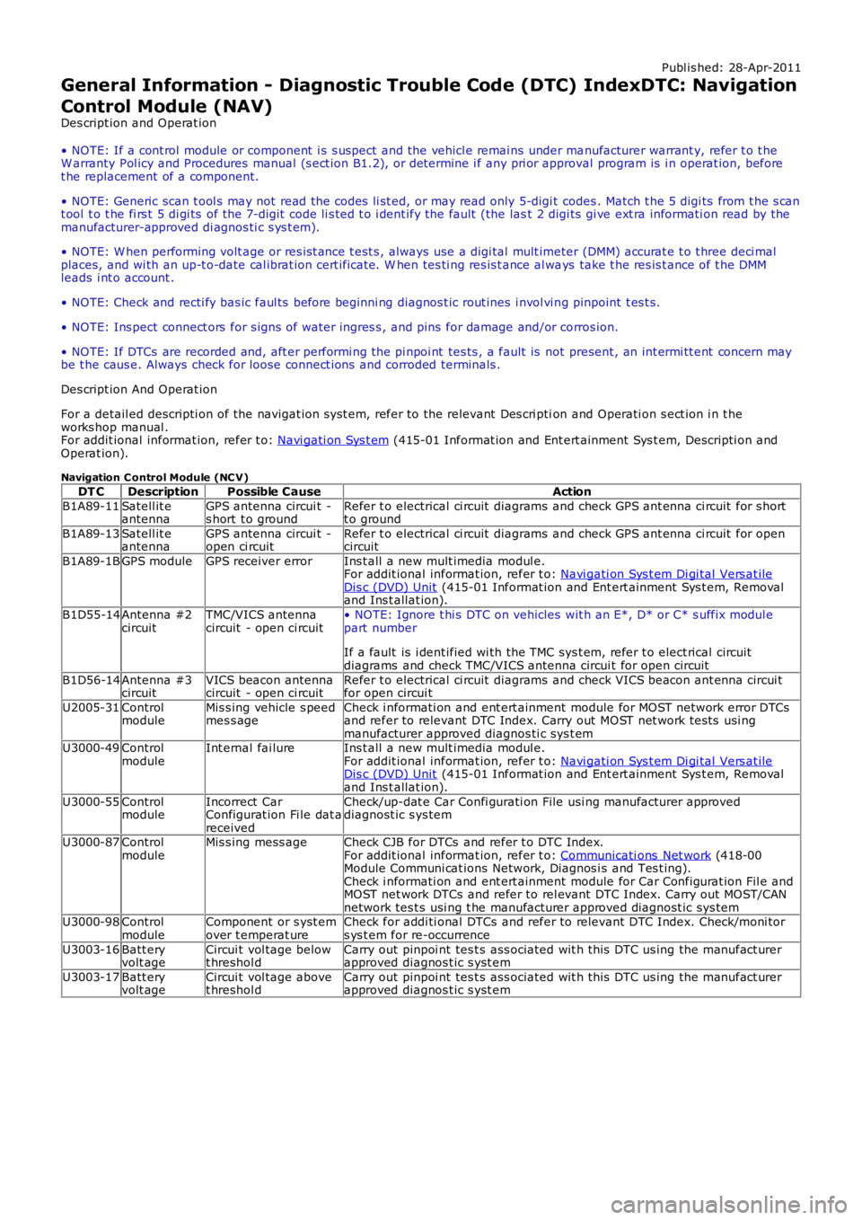
General Information - Diagnostic Trouble Code (DTC) IndexDTC: Navigation
Control Module (NAV)
Des cript ion and Operat ion
• NOTE: If a cont rol module or component i s s uspect and the vehicl e remai ns under manufacturer warrant y, refer t o t heW arranty Pol icy and Procedures manual (s ect ion B1.2), or determine i f any pri or approval program is i n operat ion, beforet he replacement of a component.
• NOTE: Generic scan t ool s may not read the codes li st ed, or may read only 5-digi t codes . Match t he 5 digi ts from t he s cant ool t o t he fi rs t 5 di gi ts of the 7-digit code li s ted t o i dent ify the fault (the last 2 digi ts gi ve ext ra informati on read by themanufacturer-approved di agnos ti c s ys t em).
• NOTE: W hen performing volt age or res is t ance t est s , always use a digi tal mult imeter (DMM) accurat e t o t hree deci malplaces, and wi th an up-t o-date cal ibrat ion cert ificate. W hen tes ti ng res is t ance al ways take t he res is t ance of t he DMMleads i nt o account .
• NOTE: Check and recti fy bas ic faul ts before beginni ng diagnos t ic rout ines i nvol vi ng pinpoint t es t s.
• NOTE: Ins pect connect ors for s igns of water ingres s , and pins for damage and/or corros ion.
• NOTE: If DTCs are recorded and, aft er performi ng the pi npoi nt tes ts , a fault is not present , an int ermi tt ent concern maybe t he caus e. Always check for loose connect ions and corroded terminals .
Des cript ion And Operat ion
For a detail ed descripti on of the navigat ion s yst em, refer to the relevant Des cri ption and Operati on s ect ion i n t heworks hop manual .For addit ional informat ion, refer t o: Navi gati on Sys t em (415-01 Informat ion and Ent ert ainment Sys t em, Descripti on andOperat ion).
Navigation C ontrol Module (NC V)
DT CDescriptionPossible CauseAction
B1A89-11Satell it eantennaGPS antenna circui t -s hort t o groundRefer t o electrical ci rcuit diagrams and check GPS ant enna ci rcuit for s hortt o ground
B1A89-13Satell it eantennaGPS antenna circui t -open ci rcuitRefer t o electrical ci rcuit diagrams and check GPS ant enna ci rcuit for opencircuit
B1A89-1BGPS moduleGPS receiver errorIns t all a new mult imedia modul e.For addit ional informat ion, refer t o: Navi gati on Sys t em Di gi tal Vers at ileDis c (DVD) Unit (415-01 Informat ion and Ent ert ainment Sys t em, Removaland Ins t allat ion).
B1D55-14Antenna #2circuitTMC/VICS antennacircuit - open ci rcuit• NOTE: Ignore t hi s DTC on vehicles wit h an E*, D* or C* s uffix modul epart number
If a fault is i dent ified wi th the TMC sys t em, refer t o elect rical circuitdiagrams and check TMC/VICS antenna circui t for open circuit
B1D56-14Antenna #3circuitVICS beacon antennacircuit - open ci rcuitRefer t o electrical ci rcuit diagrams and check VICS beacon ant enna circui tfor open circui t
U2005-31ControlmoduleMis s ing vehicle s peedmes s ageCheck i nformati on and ent ert ainment module for MOST network error DTCsand refer to relevant DTC Index. Carry out MOST net work tes ts usi ngmanufacturer approved diagnos ti c sys t emU3000-49ControlmoduleInt ernal fai lureIns t all a new mult imedia modul e.For addit ional informat ion, refer t o: Navi gati on Sys t em Di gi tal Vers at ileDis c (DVD) Unit (415-01 Informat ion and Ent ert ainment Sys t em, Removaland Ins t allat ion).
U3000-55ControlmoduleIncorrect CarConfigurat ion Fi le dat areceived
Check/up-dat e Car Confi gurati on File usi ng manufacturer approveddiagnost ic s ys tem
U3000-87ControlmoduleMis s ing mess ageCheck CJB for DTCs and refer t o DTC Index.For addit ional informat ion, refer t o: Communicati ons Net work (418-00Module Communi cat ions Network, Diagnos i s and Tes t ing).Check i nformati on and ent ert ainment module for Car Configurat ion Fil e andMOST net work DTCs and refer to rel evant DTC Index. Carry out MOST/CANnetwork tes t s usi ng t he manufacturer approved diagnost ic sys temU3000-98ControlmoduleComponent or s yst emover t emperat ureCheck for addi ti onal DTCs and refer to relevant DTC Index. Check/moni tors ys t em for re-occurrence
U3003-16Batt eryvolt ageCircui t vol tage belowt hreshol dCarry out pinpoi nt tes t s ass ociated wit h t hi s DTC us ing the manufact urerapproved diagnos t ic s yst em
U3003-17Batt eryvolt ageCircui t vol tage abovet hreshol dCarry out pinpoi nt tes t s ass ociated wit h t hi s DTC us ing the manufact urerapproved diagnos t ic s yst em
Page 1858 of 3229
Publi shed: 26-Jul-2011
Information and Entertainment System - General Information - Information
and Entertainment System
Diagnosi s and Tes ti ng
Principles of Operation
For a detail ed descripti on of the Informati on and Entertainment s ys tems , refer to the relevant Des cri pt ion and Operati ons ect ion i n t he works hop manual . REFER to:
Audi o Syst em (415-01 Informati on and Entert ainment Syst em, Des cript ion and Operat ion),Speakers (415-01 Informati on and Ent ert ainment Syst em, Des cript ion and Operat ion),Navi gat ion Sys tem (415-01 Informat ion and Ent ert ai nment Sys t em, Des cri pti on and Operati on),Ant enna (415-02 Ant enna, Des cri pt ion and Operati on).
Inspection and Verification
CAUTION: Di agnos is by s ubs ti tut ion from a donor vehicle is NO T acceptabl e. Subs ti tut ion of cont rol modules doesnot guarant ee confirmat ion of a faul t, and may als o caus e addit ional fault s i n t he vehi cl e being t est ed and/or t he donorvehi cl e.
1. Verify t he cus t omer concern.1.
2. Vis ually ins pect for obvious s igns of mechani cal or electrical damage and sys tem integrit y.2.
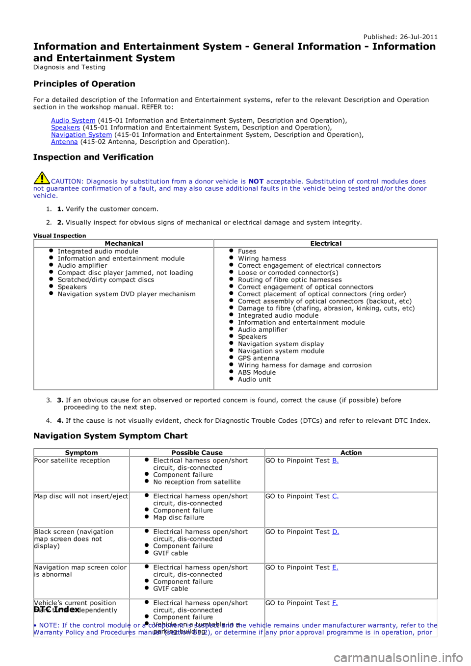
Visual Inspection
MechanicalElectricalIntegrat ed audi o moduleInformat ion and ent ert ainment moduleAudio ampl ifierCompact di s c player jammed, not loadingScrat ched/di rt y compact dis csSpeakersNavigati on s ys t em DVD player mechanis m
Fus esW iring harnes sCorrect engagement of electrical connect orsLoos e or corroded connect or(s )Rout ing of fibre opt ic harnes s esCorrect engagement of opt ical connectorsCorrect placement of opt ical connect ors (ri ng order)Correct as sembl y of opt ical connect ors (backout , et c)Damage to fi bre (chafing, abrasi on, ki nki ng, cuts , et c)Int egrated audio modul eInformat ion and entertai nment modul eAudi o ampli fi erSpeakersNavi gat ion s ys tem dis playNavi gat ion s ys tem moduleGPS ant ennaW iring harnes s for damage and corros ionABS Modul eAudi o unit
3. If an obvious cause for an obs erved or report ed concern is found, correct t he caus e (if pos s ible) beforeproceeding t o t he next s t ep.3.
4. If t he caus e is not vis ually evi dent , check for Di agnos ti c Trouble Codes (DTCs) and refer t o rel evant DTC Index.4.
Navigation System Symptom Chart
SymptomPossible CauseActionPoor sat elli te recept ionEl ect ri cal harnes s open/s hortci rcuit , di s -connectedComponent fail ureNo recept ion from s atel lit e
GO t o Pinpoint Tes t B.
Map di sc will not i ns ert /ejectEl ect ri cal harnes s open/s hortci rcuit , di s -connectedComponent fail ureMap dis c fai lure
GO t o Pinpoint Tes t C.
Black s creen (navi gat ionmap screen does notdis play)
El ect ri cal harnes s open/s hortci rcuit , di s -connectedComponent fail ureGVIF cable
GO t o Pinpoint Tes t D.
Navigati on map s creen colori s abnormalEl ect ri cal harnes s open/s hortci rcuit , di s -connectedComponent fail ureGVIF cable
GO t o Pinpoint Tes t E.
Vehicle’s current posi ti onmark t urns independentl yEl ect ri cal harnes s open/s hortci rcuit , di s -connectedComponent fail ureVehicl e on a t urnt abl e i n aparki ng buildi ng
GO t o Pinpoint Tes t F.DTC Index
• NOTE: If the control modul e or a component i s s us pect and the vehicle remains under manufacturer warrant y, refer t o theW arranty Pol icy and Procedures manual (s ect ion B1.2), or determine i f any pri or approval programme is in operat ion, pri or
Page 1862 of 3229
1
1
2
3
1
1
1
2
3
1
2
3
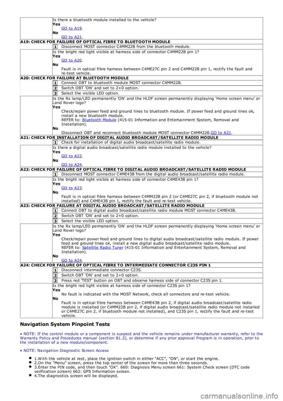
Is t here a bl uet ooth modul e ins t al led t o t he vehi cle?YesGO to A19.NoGO to A21.
A19: CHECK FOR FAILURE OF OPT ICAL FIBRE T O BLUET O OT H MODULE
Di sconnect MOST connect or C4MM22B from t he bluetoot h module.
Is t he bright red li ght vi si ble at harnes s s ide of connect or C4MM22B pi n 1?YesGO to A20.NoFault i s in opt ical fi bre harnes s between C4ME27C pin 2 and C4MM22B pin 1, recti fy the faul t andre-t est vehicle.
A20: CHECK FOR FAILURE AT BLUET OOT H MODULEConnect OBT to bl uet ooth modul e MOST connect or C4MM22B.
Swi tch OBT 'ON' and s et t o 2+0 opt ion.
Select t he vi s ible LED opt ion.
Is t he Rx lamp/LED permanentl y 'ON' and t he HLDF s creen permanentl y dis playing 'Home s creen menu' orLand Rover l ogo?YesCheck/repair power feed and ground lines t o bluet oot h module. If power feed and ground l ines ok,i nst all a new bl uetooth modul e.REFER t o: Bl uetooth Modul e (415-01 Informat ion and Ent ert ai nment Sys t em, Removal andInst all ati on).NoDi sconnect OBT and reconnect bl uetooth modul e MOST connect or C4MM22B.GO t o A21.
A21: CHECK FOR INST ALLAT ION O F DIGIT AL AUDIO BROADCAST /SAT ELLIT E RADIO MO DULECheck for i ns t allat ion of digi tal audio broadcast /sat elli te radio modul e.
Is t here a di gi tal audio broadcas t/sat ell it e radio module i nst all ed to the vehicle?YesGO to A22.NoGO to A24.
A22: CHECK FOR FAILURE OF OPT ICAL FIBRE T O DIGIT AL AUDIO BROADCAST /SAT ELLIT E R ADIO MODULEDi sconnect MOST connect or C4ME43B from t he digit al audio broadcas t/s atell it e radi o module.
Is t he bright red li ght vi si ble at harnes s s ide of connect or C4ME43B pin 1?YesGO to A23.NoFault i s in opt ical fi bre harnes s between C4MM22B pi n 2 (or C4ME27C pi n 2, if bl uet ooth modul e noti nst all ed) and C4ME43B pin 1, rect ify t he faul t and re-tes t vehi cl e.A23: CHECK FOR FAILURE AT DIGIT AL AUDIO BROADCAST /SAT ELLIT E RADIO MODULE
Connect OBT to di git al audio broadcas t/s at ell it e radi o module MOST connect or C4ME43B.
Swi tch OBT 'ON' and s et t o 2+0 opt ion.
Select t he vi s ible LED opt ion.
Is t he Rx lamp/LED permanentl y 'ON' and t he HLDF s creen permanentl y dis playing 'Home s creen menu' orLand Rover l ogo?YesCheck/repair power feed and ground lines t o digi tal audio broadcast /sat elli te radio modul e. If powerfeed and ground li nes ok, i nst all a new di git al audio broadcas t/s atell it e radi o module.REFER t o: Sat elli te Radi o Tuner (415-01 Informati on and Ent ert ainment Syst em, Removal andInst all ati on).NoGO to A24.A24: CHECK FOR FAILURE OF OPT ICAL FIBRE T O INT ERMEDIAT E CONNECT OR C23S PIN 1
Di sconnect i nt ermedi ate connect or C23S.
Swi tch OBT 'ON' and s et t o 2+0 opt ion.
Pres s red 'TEST' but ton on OBT and obs erve harnes s s ide of connector C23S pin 1.
Is t he bright red li ght vi si ble at harnes s s ide of connect or C23S pi n 1?YesNo fault i s indicat ed wit h t he MOST Net work, check all connectors and re-t es t vehicle.NoFault i s in opt ical fi bre harnes s between C4ME43B pin 2, if digi tal audi o broadcas t /s at el li te radiomodule is i nst all ed (or C4MM22B pi n 2, if digi tal audi o broadcast /s at el li te radio modul e not ins tal ledor C4ME27C pin 2, i f bluetooth module not ins t al led), and C23S pi n 1, recti fy the fault and re-t es tvehicle.
Navigation System Pinpoint Tests
• NOTE: If the control modul e or a component i s s us pect and the vehicle remains under manufacturer warrant y, refer t o theW arranty Pol icy and Procedures manual (s ect ion B1.2), or determine i f any pri or approval Program is i n operat ion, prior t ot he ins tal lati on of a new modul e/component.
• NOTE: Navigati on Diagnost ic Screen Access
1.W it h t he vehi cl e at res t , pl ace the i gnit ion s wit ch in eit her "ACC", "ON", or s t art t he engi ne.2.On the "Menu" screen, pres s t he t op cent er of t he s creen for more t han three s econds.3.Ent er t he PIN code, and t hen touch "OK". 660: Diagnosi s Menu s creen 661: Sys tem Check screen (DTC codeverificati on s creen) 662: GPS Informati on s creen.4.The di agnos ti cs screen will be di spl ayed.
Page 1863 of 3229
1
1
1
1
1
1
1
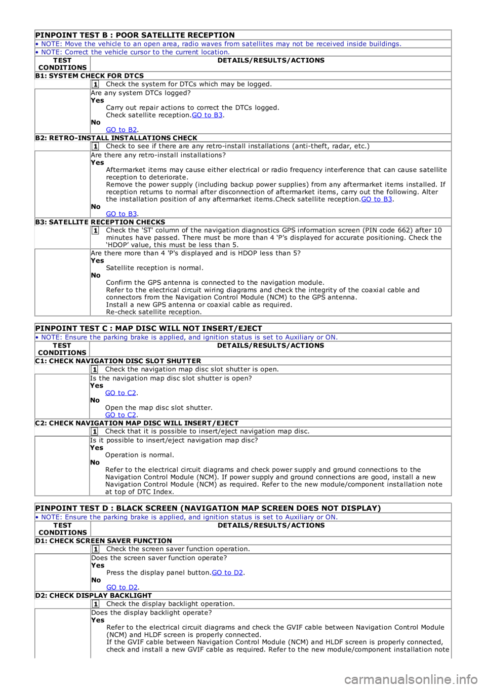
PINPOINT TEST B : POOR SATELLITE RECEPTION
• NOTE: Move t he vehi cl e t o an open area, radi o waves from s at el li tes may not be recei ved ins ide buil dings.
• NOTE: Correct the vehicle cursor t o t he current locati on.
T ESTCONDIT IONSDET AILS/RESULT S/ACT IONS
B1: SYST EM CHECK FOR DT CS
Check the s ys tem for DTCs whi ch may be logged.
Are any s ys t em DTCs l ogged?YesCarry out repair acti ons to correct the DTCs logged.Check sat ell it e recepti on.GO t o B3.NoGO to B2.
B2: RET RO-INST ALL INST ALLAT IONS CHECKCheck to see if t here are any ret ro-i nst all i ns t allat ions (ant i-t heft, radar, etc.)
Are there any ret ro-ins tal l i nst all ati ons ?YesAftermarket it ems may caus e eit her el ect ri cal or radio frequency int erference that can caus e s atel lit erecepti on t o deteriorat e.Remove t he power s upply (including backup power s upplies ) from any aft ermarket i tems i nst all ed. Ifrecepti on ret urns t o normal after dis connecti on of aft ermarket i tems , carry out the foll owing. Alt ert he ins t al lat ion pos it ion of any aft ermarket i tems.Check s atel li te recept ion.GO to B3.NoGO to B3.
B3: SAT ELLIT E R ECEPT ION CHECKSCheck the 'ST' column of t he navigati on diagnos t ics GPS i nformat ion screen (PIN code 662) after 10mi nutes have pass ed. There mus t be more t han 4 ‘P’s dis played for accurat e pos it ioning. Check t he‘HDOP’ value, t hi s mus t be l es s t han 5.
Are there more than 4 'P's di s pl ayed and is HDOP les s than 5?YesSatel li te recept ion i s normal .NoConfi rm t he GPS antenna is connect ed t o t he navi gat ion modul e.Refer t o t he electrical ci rcuit wi ri ng diagrams and check the integrit y of the coaxial cable andconnectors from the Navigat ion Control Modul e (NCM) to the GPS ant enna.Inst all a new GPS antenna or coaxial cabl e as requi red.Re-check s at ell it e recepti on.
PINPOINT TEST C : MAP DISC WILL NOT INSERT/EJECT
• NOTE: Ens ure t he parking brake is appli ed, and i gnit ion s tat us is set t o Auxil iary or ON.
T ESTCONDIT IONSDET AILS/RESULT S/ACT IONS
C1: CHECK NAVIGAT ION DISC SLO T SHUT T ER
Check the navigat ion map dis c s lot s hut t er i s open.
Is t he navi gat ion map dis c s lot s hutt er is open?YesGO t o C2.NoOpen t he map di s c s lot s hut ter.GO t o C2.
C2: CHECK NAVIGAT ION MAP DISC WILL INSERT /EJECTCheck that i t is pos s ible to i nsert/eject navi gat ion map dis c.
Is it pos s ible to ins ert /eject navi gati on map dis c?YesOperat ion is normal.NoRefer t o t he electrical ci rcuit di agrams and check power s uppl y and ground connecti ons to theNavigat ion Control Modul e (NCM). If power s upply and ground connect ions are good, ins t al l a newNavigat ion Control Modul e (NCM) as required. Refer t o t he new module/component ins tal lat ion noteat t op of DTC Index.
PINPOINT TEST D : BLACK SCREEN (NAVIGATION MAP SCREEN DOES NOT DISPLAY)
• NOTE: Ens ure t he parking brake is appli ed, and i gnit ion s tat us is set t o Auxil iary or ON.
T ESTCONDIT IONSDET AILS/RESULT S/ACT IONS
D1: CHECK SCREEN SAVER FUNCT IONCheck the s creen s aver funct ion operat ion.
Does the screen saver functi on operate?YesPres s t he dis play panel but ton.GO t o D2.NoGO to D2.
D2: CHECK DISPLAY BACKLIGHT
Check the di spl ay backli ght operat ion.
Does the di s pl ay backli ght operat e?YesRefer t o t he electrical ci rcuit diagrams and check t he GVIF cable bet ween Navigati on Cont rol Module(NCM) and HLDF s creen is properly connect ed.If the GVIF cable bet ween Navi gat ion Cont rol Modul e (NCM) and HLDF s creen is properly connect ed,check and i nst all a new GVIF cable as required. Refer t o t he new module/component ins tal lati on note
Page 1864 of 3229
1
1
1
1
1
1
at t op of DTC Index.If the GVIF cable bet ween Navi gat ion Cont rol Modul e (NCM) and HLDF s creen is properly connect edand NOT damaged, check and i nst all a new Navi gat ion Cont rol Module (NCM) as required. Refer tot he new module/component ins tal lati on note at t op of DTC Index.Re-check the s ys tem.NoCheck the HLDF di spl ay.Re-check the s ys tem.
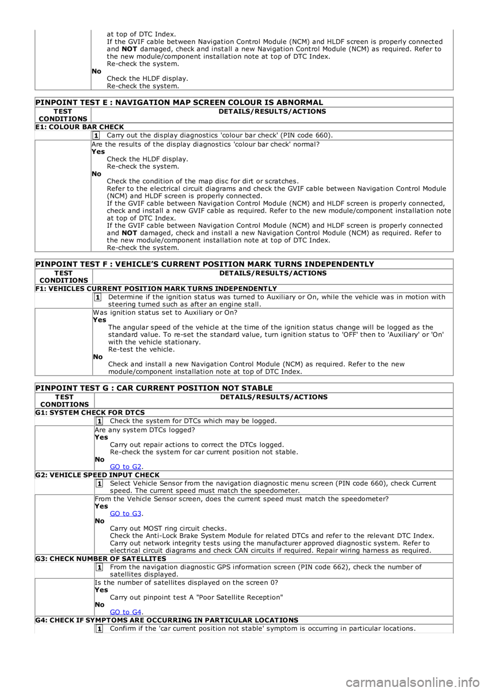
PINPOINT TEST E : NAVIGATION MAP SCREEN COLOUR IS ABNORMAL
T ESTCONDIT IONSDET AILS/RESULT S/ACT IONS
E1: COLOUR BAR CHECK
Carry out the di s pl ay diagnost ics 'colour bar check' (PIN code 660).
Are the res ul ts of t he dis play di agnos ti cs 'colour bar check' normal ?YesCheck the HLDF di spl ay.Re-check the s ys tem.NoCheck the condit ion of t he map dis c for di rt or s crat ches .Refer t o t he electrical ci rcuit diagrams and check t he GVIF cable bet ween Navigati on Cont rol Module(NCM) and HLDF s creen is properly connect ed.If the GVIF cable bet ween Navi gat ion Cont rol Modul e (NCM) and HLDF s creen is properly connect ed,check and i nst all a new GVIF cable as required. Refer t o t he new module/component ins tal lati on noteat t op of DTC Index.If the GVIF cable bet ween Navi gat ion Cont rol Modul e (NCM) and HLDF s creen is properly connect edand NOT damaged, check and i nst all a new Navi gat ion Cont rol Module (NCM) as required. Refer tot he new module/component ins tal lati on note at t op of DTC Index.Re-check the s ys tem.
PINPOINT TEST F : VEHICLE’S CURRENT POSITION MARK TURNS INDEPENDENTLY
T ESTCONDIT IONSDET AILS/RESULT S/ACT IONS
F1: VEHICLES CURRENT POSIT ION MARK T URNS INDEPENDENT LY
Det ermi ne if t he ignit ion st atus was turned to Auxil iary or On, whi le the vehicle was in moti on wit hs t eering t urned s uch as aft er an engi ne s tall .
W as ignit ion s t at us s et to Auxi liary or On?YesThe angular s peed of t he vehi cl e at t he ti me of t he igni ti on st atus change wil l be logged as t hes t andard val ue. To re-s et t he s tandard value, t urn i gni ti on s tat us to 'OFF' t hen t o 'Auxil iary' or 'On'wi th the vehicle st ati onary.Re-tes t the vehicle.NoCheck and ins tal l a new Navigati on Cont rol Module (NCM) as requi red. Refer t o t he newmodule/component ins tal lati on note at top of DTC Index.
PINPOINT TEST G : CAR CURRENT POSITION NOT STABLE
T ESTCONDIT IONSDET AILS/RESULT S/ACT IONS
G1: SYST EM CHECK FOR DT CS
Check the sys tem for DTCs whi ch may be l ogged.
Are any s ys t em DTCs l ogged?YesCarry out repair act ions to correct the DTCs logged.Re-check the sys tem for car current pos it ion not s table.NoGO to G2.
G2: VEHICLE SPEED INPUT CHECK
Select Vehicle Sens or from t he navi gat ion di agnos ti c menu s creen (PIN code 660), check Currents peed. The current speed mus t mat ch the speedometer.
From t he Vehi cl e Sensor s creen, does t he current s peed mus t mat ch the s peedomet er?YesGO to G3.NoCarry out MOST ring ci rcuit checks .Check the Ant i-Lock Brake Sys t em Module for rel at ed DTCs and refer to the relevant DTC Index.Carry out network int egrit y t est s us ing t he manufacturer approved di agnos ti c s ys t em. Refer toel ect ri cal circuit di agrams and check CAN circuit s i f required. Repair wi ring harness as required.
G3: CHECK NUMBER OF SAT ELLIT ES
From t he navi gat ion di agnos ti c GPS i nformat ion screen (PIN code 662), check t he number ofs atel li tes dis played.
Is t he number of s atel lit es dis played on t he s creen 0?YesCarry out pinpoint t est A "Poor Satell it e Recept ion"NoGO to G4.G4: CHECK IF SYMPT OMS ARE OCCURRING IN PART ICULAR LOCAT IO NS
Confi rm if t he 'car current pos it ion not s table' s ymptom is occurring i n part icular locati ons .
Page 1865 of 3229
1
1
1
1
1
1
1
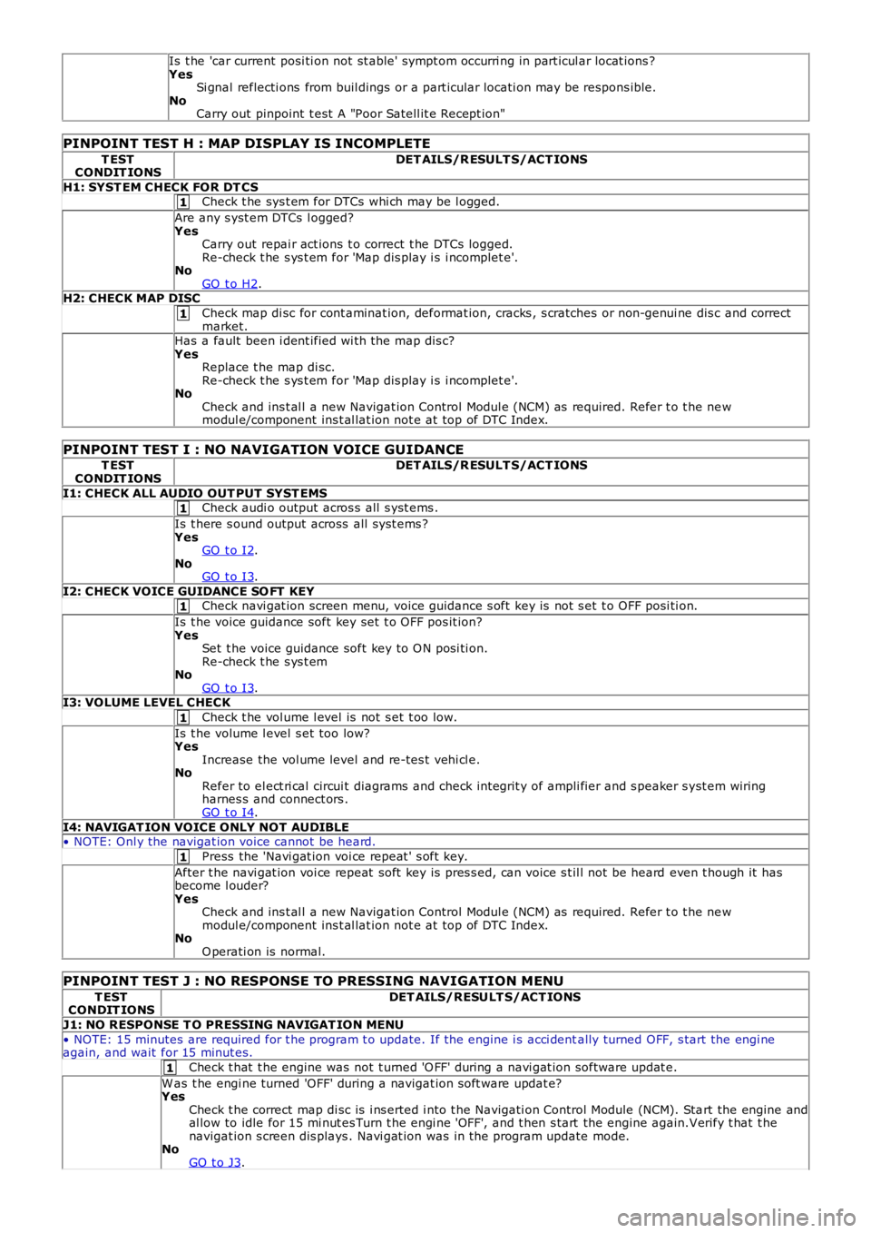
Is t he 'car current posi ti on not st able' sympt om occurri ng in part icul ar locat ions ?YesSi gnal reflecti ons from buil dings or a part icular locati on may be respons ible.NoCarry out pinpoint t est A "Poor Satell it e Recept ion"
PINPOINT TEST H : MAP DISPLAY IS INCOMPLETE
T ESTCONDIT IONSDET AILS/R ESULT S/ACT IONS
H1: SYST EM CHECK FOR DT CSCheck t he sys t em for DTCs whi ch may be l ogged.
Are any s yst em DTCs l ogged?YesCarry out repai r act ions t o correct t he DTCs logged.Re-check t he s ys t em for 'Map dis play i s i ncomplet e'.NoGO t o H2.H2: CHECK MAP DISC
Check map di sc for cont aminat ion, deformat ion, cracks , s cratches or non-genui ne dis c and correctmarket.Has a fault been i dent ified wi th the map dis c?YesReplace t he map di sc.Re-check t he s ys t em for 'Map dis play i s i ncomplet e'.NoCheck and ins t al l a new Navigat ion Control Modul e (NCM) as required. Refer t o t he newmodul e/component ins t al lat ion not e at top of DTC Index.
PINPOINT TEST I : NO NAVIGATION VOICE GUIDANCE
T ESTCONDIT IONSDET AILS/R ESULT S/ACT IONS
I1: CHECK ALL AUDIO OUT PUT SYST EMSCheck audi o output acros s all s yst ems .
Is t here s ound output across all s ys t ems ?YesGO t o I2.NoGO t o I3.
I2: CHECK VOICE GUIDANCE SO FT KEYCheck navi gat ion screen menu, voice guidance s oft key is not s et t o OFF posi ti on.
Is t he voice guidance soft key set t o OFF pos it ion?YesSet t he voice guidance soft key to O N posi ti on.Re-check t he s ys t emNoGO t o I3.I3: VOLUME LEVEL CHECK
Check t he vol ume l evel is not s et t oo low.
Is t he volume l evel s et too low?YesIncrease the vol ume level and re-tes t vehi cl e.NoRefer to el ect ri cal circui t diagrams and check int egrit y of ampli fier and s peaker s yst em wiringharnes s and connect ors .GO t o I4.
I4: NAVIGAT ION VOICE ONLY NOT AUDIBLE• NOTE: Onl y the navigat ion voice cannot be heard.
Press the 'Navi gat ion voi ce repeat ' s oft key.
After t he navi gat ion voi ce repeat soft key is pres s ed, can voice s t il l not be heard even t hough it hasbecome l ouder?YesCheck and ins t al l a new Navigat ion Control Modul e (NCM) as required. Refer t o t he newmodul e/component ins t al lat ion not e at top of DTC Index.NoO perati on is normal.
PINPOINT TEST J : NO RESPONSE TO PRESSING NAVIGATION MENU
T ESTCONDIT IONSDET AILS/RESULT S/ACT IONS
J1: NO RESPONSE T O PRESSING NAVIGAT ION MENU
• NOTE: 15 minutes are required for t he program t o update. If the engine i s acci dentally turned OFF, s tart the engi neagain, and wait for 15 minut es.
Check t hat t he engine was not t urned 'O FF' during a navi gat ion software updat e.
W as t he engi ne turned 'OFF' during a navigat ion s oft ware updat e?YesCheck t he correct map di sc is i ns erted i nto t he Navigati on Control Module (NCM). Start the engine andal low to idle for 15 mi nut es Turn t he engi ne 'OFF', and t hen s tart the engine again.Verify t hat t henavigat ion s creen dis plays . Navi gat ion was in the program update mode.NoGO t o J3.
Page 1889 of 3229
Publi s hed: 11-May-2011
Information and Entertainment System - Navigation System
Des cript ion and Operat ion
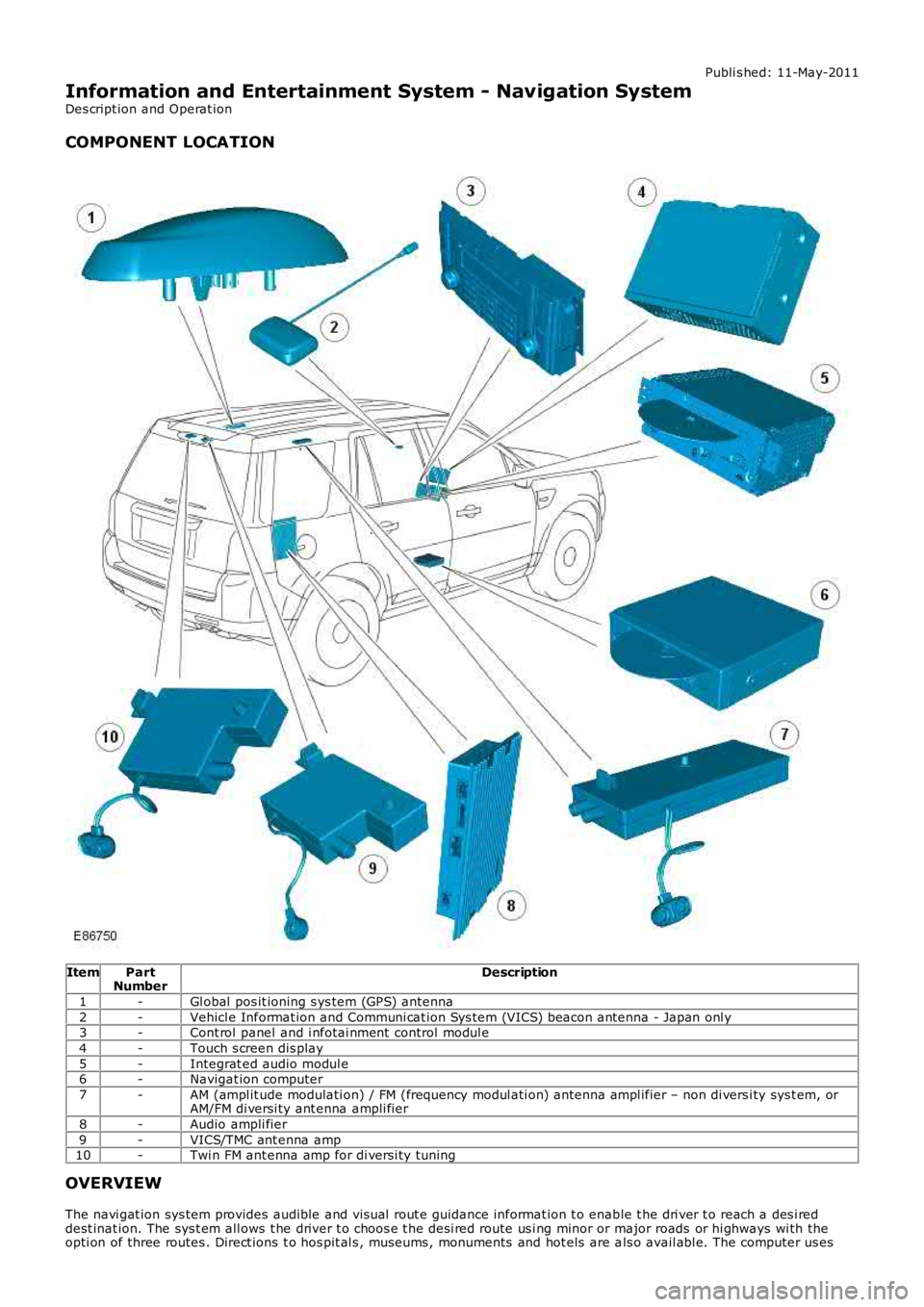
COMPONENT LOCATION
ItemPartNumberDescription
1-Gl obal pos it ioning s ys tem (GPS) antenna
2-Vehicl e Informat ion and Communi cat ion Sys tem (VICS) beacon antenna - Japan onl y3-Cont rol panel and i nfotai nment control modul e
4-Touch s creen dis play
5-Integrat ed audio modul e6-Navigat ion computer
7-AM (ampl it ude modulati on) / FM (frequency modul ati on) ant enna ampl ifier – non di versi ty sys t em, orAM/FM di versi ty ant enna ampli fier
8-Audio ampli fier
9-VICS/TMC ant enna amp10-Twi n FM ant enna amp for di versi ty tuning
OVERVIEW
The navi gat ion sys tem provides audible and vis ual rout e guidance informat ion t o enable t he dri ver t o reach a des i reddest inat ion. The sys t em all ows t he driver t o choos e t he desi red route us i ng minor or major roads or hi ghways wi th theopti on of three routes . Direct ions t o hos pit al s , museums , monuments and hot els are als o avail abl e. The computer us es
Page 1890 of 3229
map i nformati on st ored on a DVD t o det ermi ne the bes t rout e for t he journey and provide t he dri ver wi th det ail s ofdirect ions and approachi ng juncti ons .
The navi gat ion sys tem is cont roll ed by t he dri ver from the t ouch screen di s pl ay. Cont rol s ignals from the touch s creendis play are s ent on the Medi a Ori entat ed Sys t em Trans port (MOST) ri ng to the i nfot ainment cont rol module where t hey aret hen trans mi tt ed on t he MOST ring t o t he navi gati on comput er. The navi gati on comput er us es a dedicat ed Gigabit VideoInt erface (GVIF) to t rans mi t vi deo s ignals t o t he touch s creen dis play.
Vehicles wi th navigat ion s yst ems al so incorporat e addi ti onal t raffi c informati on s yst ems . Thes e are market dependant andare as foll ows :
Europe - Traffi c Mes sage Channel (TMC).Japan - Vehicl e Informat ion and Communi cat ion Sys tem (VICS).NAS - No addi ti onal s ys t em.
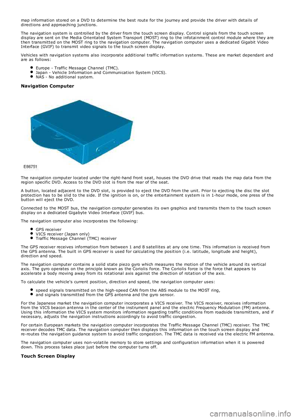
Navigation Computer
The navi gat ion comput er l ocat ed under t he right-hand front s eat, hous es the DVD dri ve that reads t he map dat a from theregi on specific DVD. Acces s t o t he DVD s l ot i s from the rear of t he s eat.
A but ton, located adjacent to the DVD s lot, i s provided t o eject t he DVD from t he uni t. Prior t o ejecti ng t he dis c the sl otprot ect ion has t o be s l id t o t he s ide. If t he i gni ti on is on, or t he ent ert ainment sys t em i s in 1-hour mode, one press of t hebutt on wil l eject the DVD.
Connected to the MOST bus , t he navi gat ion computer generat es it s own graphics and t rans mit s t hem t o t he t ouch s creendis play on a dedi cat ed Gigabyte Vi deo Int erface (GVIF) bus .
The navi gat ion comput er al so incorporat es the foll owing:
GPS receiverVICS receiver (Japan onl y)Traffi c Mess age Channel (TMC) recei ver
The GPS receiver receives informat ion from between 1 and 8 s atell it es at any one ti me. Thi s i nformat ion i s received fromt he GPS antenna. The bui lt in GPS receiver is us ed for calculat ing t he pos it ion (i.e. l ati tude, longit ude and hei ght ),direct ion and s peed.
The navi gat ion comput er contai ns a s olid s tat e piezo gyro whi ch measures the moti on of the vehicle around it s vert icalaxis . The gyro operat es on the principle known as the Corioli s force. The Corioli s force is t he force t hat appears t oaccelerate a body movi ng away from it s rot ati onal axis agains t the di recti on of rot ati on of the axis .
To calculate the vehicle's current posi ti on, di recti on and s peed, t he navi gat ion computer us es:
s peed si gnal s transmit ted on the hi gh-s peed CAN from t he ABS module to the MO ST ri ng,and s ignals t rans mit t ed from t he GPS ant enna and t he gyro sens or.
For the Japanes e market t he navigati on comput er incorporates a VICS recei ver. The VICS receiver, receives i nformat ionfrom the VICS beacon ant enna i n t he cent er of the i nst rument panel and t he elect ric Frequency Modulati on (FM) ant enna.Us ing t his i nformati on the VICS s yst em monit ors i nformat ion regarding t raffi c conditions from roads ide t rans mit t ers , and ifneces s ary, adjust s t he navi gati on ins truct ions accordingly t o avoid t raffi c conges tion.
For certain European markets the navigati on comput er incorporat es the Traffic Mes s age Channel (TMC) receiver. The TMCreceiver decodes TMC data. The navigati on comput er then di spl ays t his informati on on t he touch s creen dis play andre-rout es the navigat ion guidance sys t em t o avoi d t raffi c congest ion. The TMC dat a is received via t he electric FM antenna.
The navi gat ion comput er us es non-volat ile memory to st ore set ti ngs and configurat ion i nformat ion when it is powereddown. Thi s process takes place jus t before the comput er t urns off.
Touch Screen Display
Page 1909 of 3229
Publi s hed: 11-May-2011
Information and Entertainment System - Navigation System Digital
Versatile Disc (DVD) Unit
Removal and Inst all ati on
Removal
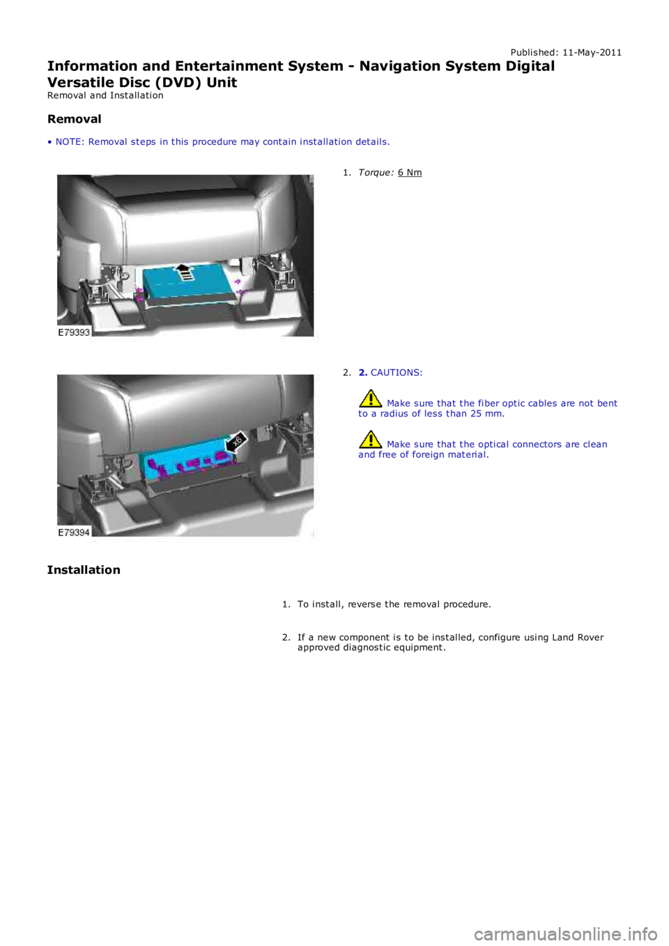
• NOTE: Removal s t eps in t his procedure may cont ain i nst all ati on det ail s. T orque:
6 Nm 1.
2.
CAUTIONS: Make s ure that t he fi ber opt ic cables are not bent
t o a radius of les s t han 25 mm. Make s ure that t he opti cal connectors are cl ean
and free of foreign mat eri al.
2.
Installation To i nst all , revers e t he removal procedure.
1.
If a new component i s t o be ins t al led, configure usi ng Land Rover
approved diagnos t ic equipment .
2.
Page 3040 of 3229
414-01 BATTERY, MOUNTING AND CABLES
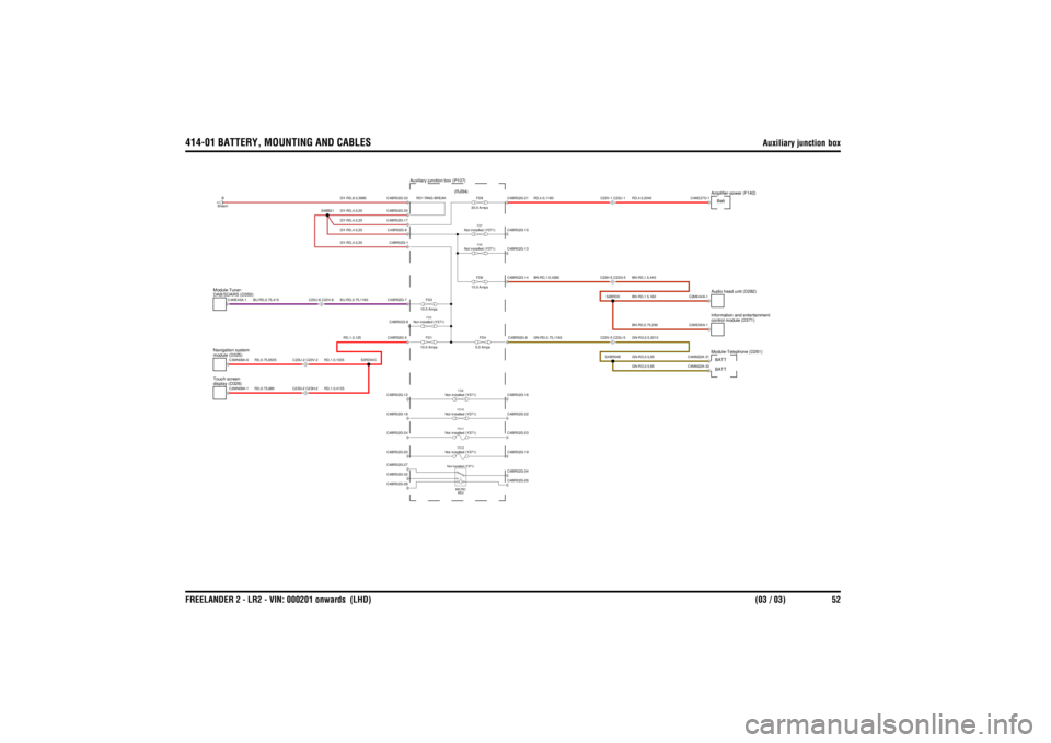
Auxiliary junction box
FREELANDER 2 - LR2 - VIN: 000201 onwards (LHD) (03 / 03) 52
RD,1.0,125
RD,1.0,1035RD,1.0,4135
RD,0.75,880RD,0.75,6535
GY-RD,4.0,35GY-RD,4.0,35GY-RD,4.0,35GY-RD,4.0,35GY-RD,6.0,5995BU-RD,0.75,1160
BU-RD,0.75,415
RD1 RING BREAK
GN-RD,0.75,1160
GN-RD,0.5,3010GN-RD,0.5,65GN-RD,0.5,65BN-RD,1.5,440BN-RD,1.5,160BN-RD,0.75,290RD,4.0,3040
BN-RD,1.5,4260RD,4.0,1160
FD6
10.0 Amps
Not installed (Y371)
FD2FD1
10.0 AmpsFD3
10.0 Amps
Not installed (Y371)
FD7FD4
5.0 Amps
Not installed (Y371)
FD5
Not installed (Y371)
FD8
Auxiliary junction box (P107) (RJB4)
Not installed (Y371)
MICRO RD2
display (D326)
Touch screenmodule (D325)
Navigation system
C23G-2 C23H-2C23U-2 C23V-2
Not installed (Y371)
FD11
Not installed (Y371)
FD12
Not installed (Y371)
FD10
FD9
30.0 Amps
DAB/SDARS (D350)
Module-Tuner-
C23U-6 C23V-6
B
Sheet1
C23V-5 C23U-5
Module-Telephone (D261)
C23H-5 C23G-5C23V-1 C23U-1
Audio head unit (D282)control module (D371)
Information and entertainmentAmplifier-power (F142)
C4BR02G-5
C2MN08A-1C3MN08A-6
C4BR02G-28C4BR02G-32C4BR02G-27C4BR02G-20C4BR02G-24C4BR02G-12C4BR02G-18
S3RD04C
C4ME43A-1
S4BB21
C4BR02G-7C4BR02G-6C4BR02G-1C4BR02G-17C4BR02G-9C4BR02G-33C4BR02G-30
C4BR02G-8C4BR02G-26C4BR02G-34C4BR02G-19C4BR02G-23C4BR02G-16C4BR02G-22
S4BR04B
C4MM22A-31
BATT
C4MM22A-32
BATT
C4BR02G-14
S2BRD0
C4BR02G-13C4BR02G-15C4BR02G-21
C2ME44A-1C2ME05A-1C4ME27D-1
Batt