head LEXUS LS430 2003 Factory Owner's Manual
[x] Cancel search | Manufacturer: LEXUS, Model Year: 2003, Model line: LS430, Model: LEXUS LS430 2003Pages: 4500, PDF Size: 87.45 MB
Page 2177 of 4500
a. Fill the rear differential carrier assy with differential gear oil equivalent.
Oil type: Differential synthetic gear oil GL-5 75W-90 or equivalent
Capacity: 1.35 +/- 0.05 liters (1.43 +/- 0.05 US qts, 1.19 +/- 0.04 Imp. qts)
67.INSPECT DIFFERENTIAL OIL (SEE ADJUSTMENT
)
68.INSTALL REAR DIFFERENTIAL FILLER PLUG
a. Using a hexagon wrench (10 mm), install the filler plug with a new gasket.
Torque: 49 N.m (500 kgf.cm, 36 ft.lbf)
69.INSTALL REAR DRIVE SHAFT ASSY LH (SEE REPLACEMENT
)
70.INSTALL REAR DRIVE SHAFT ASSY RH
HINT:
Installation procedure of the RH side is the same as that of the LH side.
71.INSTALL FRONT FLOOR HEAT INSULATOR NO.1
a. Install the front floor heat insulator No.1 with the 4 bolts.
Torque: 5.4 N.m (55 kgf.cm, 48 in..lbf)
72.INSTALL REAR WHEEL
a. Install the rear wheel with the 5 nuts.
Torque: 103 N.m (1,050 kgf.cm, 76 ft.lbf)
73. Install the ornament with the 10 bolts.
Torque: 20 N.m (204 kgf.cm, 15 ft.lbf)
74.INSTALL PROPELLER W/CENTER BEARING SHAFT ASSY (SEE OVERHAUL
)
75.FULLY TIGHTEN CENTER SUPPORT BEARING ASSY NO.1 (SEE OVERHAUL
)
SST 09922-10010
76.INSPECT AND ADJUST NO.2 AND NO.3 JOINT ANGLE (SEE OVERHAUL
)
77.INSTALL PROPELLER SHAFT HEAT INSULATOR (SEE OVERHAUL
)
78.INSTALL EXHAUST PIPE ASSY (SEE REPLACEMENT
)
79.INSTALL OXYGEN SENSOR (SEE REPLACEMENT
)
80.INSPECT AND ADJUST REAR WHEEL ALIGNMENT (SEE ADJUSTMENT
)
81.ADJUST VEHICLE HEIGHT (W/ AIR SUSPENSION) (SEE ON
-VEHICLE INSPECTION )
82.INSPECT HEADLIGHT AIM ONLY (SEE ADJUSTMENT
)
83.CHECK ABS SPEED SENSOR SIGNAL (SEE TEST MODE PROCEDURE
)
84.INSPECT AIR LEAK (W/ AIR SUSPENSION) (SEE REPLACEMENT
)
HINT:
Perform this operation onl
y when the rear differential mount cushion is replaced.
Page 2364 of 4500
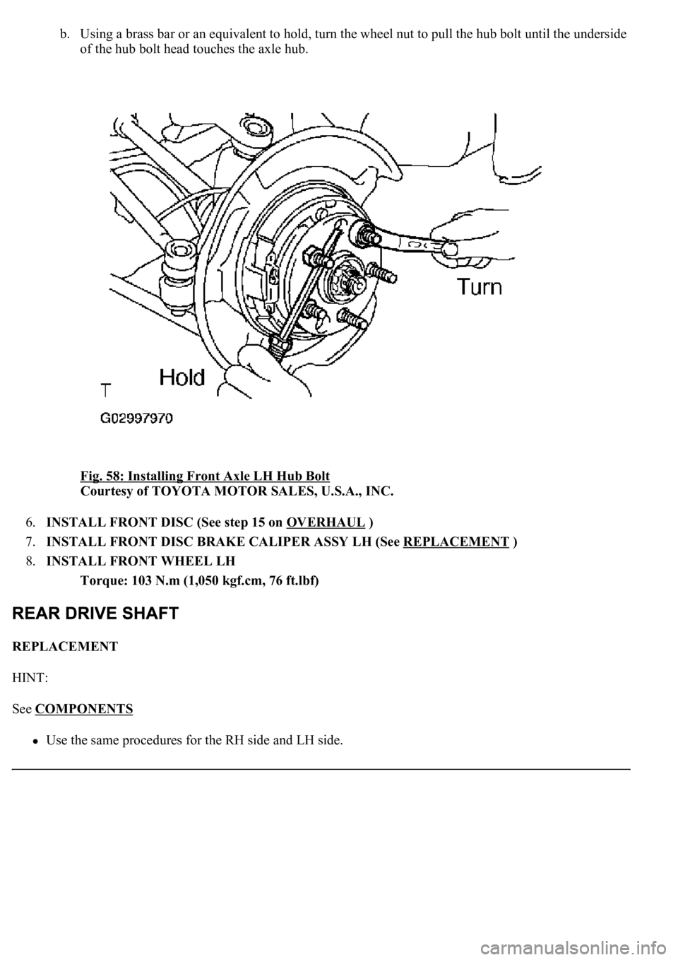
b. Using a brass bar or an equivalent to hold, turn the wheel nut to pull the hub bolt until the underside
of the hub bolt head touches the axle hub.
Fig. 58: Installing Front Axle LH Hub Bolt
Courtesy of TOYOTA MOTOR SALES, U.S.A., INC.
6.INSTALL FRONT DISC (See step 15 on OVERHAUL
)
7.INSTALL FRONT DISC BRAKE CALIPER ASSY LH (See REPLACEMENT
)
8.INSTALL FRONT WHEEL LH
Torque: 103 N.m (1,050 kgf.cm, 76 ft.lbf)
REPLACEMENT
HINT:
See COMPONENTS
<00380056004800030057004b00480003005600440050004800030053005500520046004800470058005500480056000300490052005500030057004b004800030035002b00030056004c0047004800030044005100470003002f002b00030056004c004700
4800110003[
Page 2391 of 4500
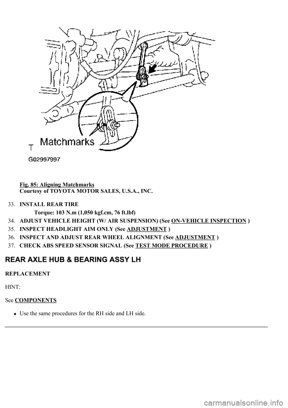
Fig. 85: Aligning Matchmarks
Courtesy of TOYOTA MOTOR SALES, U.S.A., INC.
33.INSTALL REAR TIRE
Torque: 103 N.m (1,050 kgf.cm, 76 ft.lbf)
34.ADJUST VEHICLE HEIGHT (W/ AIR SUSPENSION) (See ON
-VEHICLE INSPECTION )
35.INSPECT HEADLIGHT AIM ONLY (See ADJUSTMENT
)
36.INSPECT AND ADJUST REAR WHEEL ALIGNMENT (See ADJUSTMENT
)
37.CHECK ABS SPEED SENSOR SIGNAL (See TEST MODE PROCEDURE
)
REPLACEMENT
HINT:
See COMPONENTS
<00380056004800030057004b00480003005600440050004800030053005500520046004800470058005500480056000300490052005500030057004b004800030035002b00030056004c0047004800030044005100470003002f002b00030056004c004700
4800110003[
Page 2408 of 4500
42.ADJUST PARKING BRAKE PEDAL TRAVEL (See step 5 on ADJUSTMENT )
43.INSTALL SPEED SENSOR REAR LH
a. Install the speed sensor with the bolt.
Torque: 8.0 N.m (82 kgf.cm, 71 in.lbf)
44.INSTALL REAR DISC (See step 16 on OVERHAUL
)
45.ADJUST PARKING BRAKE SHOE CLEARANCE (See step 21 on OVERHAUL
)
46.INSTALL REAR DISC BRAKE CALIPER ASSY LH (See step 20 on REPLACEMENT
)
47.INSTALL REAR AXLE SHAFT NUT (See REPLACEMENT
)
48.INSPECT AXLE HUB BEARING LOOSENESS (See ON
-VEHICLE INSPECTION )
49.INSPECT AXLE HUB BEARING RUNOUT (See ON
-VEHICLE INSPECTION )
50.STABILIZE SUSPENSION (See step 23 on REPLACEMENT
)
51.FULLY TIGHTEN SHOCK ABSORBER ASSY REAR LH
a. Fully tighten the shock absorber assy LH with the new nut.
Torque: 70 N.m (714 kgf.cm, 52 ft.lbf)
52.INSTALL REAR TIRE
Torque: 103 N.m (1,050 kgf.cm, 76 ft.lbf)
53.ADJUST VEHICLE HEIGHT (W/ AIR SUSPENSION) (See ON
-VEHICLE INSPECTION )
54.INSPECT HEADLIGHT AIM ONLY (See ADJUSTMENT
)
55.INSPECT AND ADJUST REAR WHEEL ALIGNMENT (See ADJUSTMENT
)
56.CHECK ABS SPEED SENSOR SIGNAL (See TEST MODE PROCEDURE
)
REPLACEMENT
HINT:
See COMPONENTS
Use the same procedures for the RH side and LH side.
The procedures listed below are for the LH side.
1.REMOVE REAR TIRE
2.REMOVE REAR DISC BRAKE CALIPER ASSY LH (See REPLACEMENT
)
3.REMOVE REAR DISC (See step 15 on OVERHAUL
)
4.REMOVE REAR AXLE LH HUB BOLT
a. Using SST and a screwdriver or an equivalent to hold, remove the hub bolt.
SST 09628-10011
Page 2421 of 4500

HVAC DIAGNOSTIC TROUBLE CODE (DTC) IDENTIFICATION
LIGHTING SYSTEM DIAGNOSTIC TROUBLE CODE (DTC) IDENTIFICATION
SENSOR/SWITCH "D"/"E" VOLTAGE
CORRELATION
DTC P2121 THROTTLE/PEDAL POSITION
SENSOR/SWITCH "D" CIRCUIT
RANGE/PERFORMANCE
DTC U0001 HIGH SPEED CAN COMMUNICATION
CIRCUIT
DTCDescription
DTC B1411 ROOM TEMPERATURE SENSOR CIRCUIT
DTC B1412 AMBIENT TEMPERATURE SENSOR CIRCUIT
DTC B1413 EVAPORATOR TEMPERATURE SENSOR CIRCUIT
DTC B1415 AIR DUCT SENSOR CIRCUIT (DRIVER SIDE)
DTC B1416 AIR DUCT SENSOR CIRCUIT (PASSENGER SIDE)
DTC B1418 EMISSION GAS SENSOR CIRCUIT
DTC B1421 SOLAR SENSOR CIRCUIT (PASSENGER SIDE)
DTC B1423 PRESSURE SWITCH CIRCUIT
DTC B1424 SOLAR SENSOR CIRCUIT (DRIVER SIDE)
DTC B1428 REAR SOLAR SENSOR CIRCUIT
DTC B1432 AIR INLET DAMPER POSITION SENSOR CIRCUIT
DTC B1434 MAX COOL DAMPER POSITION SENSOR CIRCUIT (DRIVER SIDE)
DTC B1435 MAX COOL DAMPER POSITION SENSOR CIRCUIT (PASSENGER SIDE)
DTC B1442 AIR INLET DAMPER CONTROL SERVOMOTOR CIRCUIT
DTC B1451 COMPRESSOR SOLENOID CIRCUIT
DTC B1461 EMISSION GAS NOX SENSOR CIRCUIT
DTCDescription
DTC B1244 LIGHT SENSOR CIRCUIT MALFUNCTION
DTC B1268 BACK-UP COMMUNICATION BUS MALFUNCTION
DTC B2402, B2403 TRANSISTOR RELAY OVERLOAD/OVERHEAT MALFUNCTION
DTC B2412, B2413 HEADLIGHT SWIVEL MOTOR LH/RH MALFUNCTION
DTC B2414 STEERING POSITION SENSOR MALFUNCTION
DTC B2415 VEHICLE SPEED SENSOR MALFUNCTION
DTC B2416 HEIGHT CONTROL SENSOR MALFUNCTION
DTC B2417, B2418 HEADLIGHT BEAM LEVEL CONTROL MOTOR LH/RH
MALFUNCTION
Page 2433 of 4500

dynamic laser cruise control system.
Operation of the constant speed control mode is the same as that for the conventional type
cruise control system.
b. This system maintains the vehicle running at the speed that the driver has set, as long as there are
no vehicles ahead in the same lane. Then, the system maintains the vehicle distance that has been
set by the driver.
If the system detects a vehicle moving at a slower speed ahead while the driver is driving at a
constant speed, it closes the throttle valve to decelerate. If further deceleration is required, the
system controls the brake actuator in order to apply the brakes. Thereafter, if there are no vehicles
ahead within the set vehicle-to-vehicle distance because either the vehicle ahead or the driver has
changed lanes, the system accelerates slowly to reach the set vehicle speed and resumes driving at
the constant speed.
c. The constant speed control mode is designed to maintain a constant cruising speed. The vehicle-to-
vehicle distance control mode is designed to control cruising at a constant speed function,
deceleration cruising function, follow-up cruising function and acceleration cruising function.
d. The laser sensor and the distance control ECU (cruise control ECU) control the system while the
vehicle-to-vehicle distance control mode is in operation, and send signals to each actuator and
ECU.
e. In vehicle-to-vehicle distance control mode, the dynamic laser cruise control system receives
signals from the yaw rate & deceleration sensor and the steering angle sensor. Based on these
signals, it then estimates curve radius and compensates for information on the preceding vehicle
while turning. It can also compensate for the brake control when approaching another vehicle.
f. This system judges the existence of a vehicle in front and the distance to it based on the signals
from the laser sensor while the vehicle-to-vehicle distance control mode is in operation. Using this
information, the system informs the driver of any danger with the warning buzzer, performs brake
control, and turns on the stop lamp when approaching the vehicle in front.
g. The following illustration shows a control example under the following conditions: own vehicle
speed is 100 km/h (62 mph) and the speed of the vehicle in front is 80 km/h (50 mph).
Page 2486 of 4500

Fig. 53: DTC P1631 And U0100 Problem Symptom Diagnostic Chart
Courtesy of TOYOTA MOTOR SALES, U.S.A., INC.
INSPECTION PROCEDURE
HINT:
This circuit uses CAN for communication. Therefore, if there are any malfunctions in the communication
circuit, one or more DTCs in the CAN communication system is/are output.
1.GO TO CAN COMMUNICATION SYSTEM (SEE HOW TO PROCEED WITH
TROUBLESHOOTING )
CIRCUIT DESCRIPTION
The ABS & traction actuator assy (skid control ECU) receives the alarm demand signal from the ECM and
operates the skid control buzzer.
The buzzer sounds to warn that the distance between the vehicle in front and your own vehicle is shortening.
Fig. 54: DTC P1575 Problem Symptom Diagnostic
Chart
Courtesy of TOYOTA MOTOR SALES, U.S.A., INC.
HINT:
If the vehicle ahead in the same lane significantly decreases its speed or another vehicle pulls in front of your
own vehicle, adequate deceleration cannot be applied and the vehicle-to-vehicle distance will shorten. At this
time, the s
ystem sounds the buzzer and the master warning light blinks to inform the driver.
Page 2532 of 4500

1.GENERAL
a. The dynamic radar cruise control system has two cruise control modes: the constant speed control
mode and vehicle-to-vehicle distance control mode.
The vehicle-to-vehicle distance control mode is always selected when starting up the
dynamic radar cruise control system.
Operation of the constant speed control mode is the same as that for the conventional type
cruise control system.
b. This system maintains the vehicle running at the speed that the driver has set, as long as there are
no vehicles ahead in the same lane. Then, the system maintains the vehicle distance that has been
set by the driver.
If the system detects a vehicle moving at a slower speed ahead while the driver is driving at a
constant speed, it closes the throttle valve to decelerate. If further deceleration is required, the
system controls the brake actuator in order to apply the brakes. Thereafter, if there are no vehicles
ahead within the set vehicle-to-vehicle distance because either the vehicle ahead or the driver has
changed lanes, the system accelerates slowly to reach the set vehicle speed and resumes driving at
the constant speed.
c. The constant speed control mode is designed to maintain a constant cruising speed. The vehicle-to-
vehicle distance control mode is designed to control cruising at a constant speed function,
deceleration cruising function, follow-up cruising function and acceleration cruising function.
d. The millimeter wave radar sensor and the distance control ECU (cruise control ECU) control the
system while the vehicle-to-vehicle distance control mode is in operation, and send signals to each
actuator and ECU.
e. In vehicle-to-vehicle distance control mode, the dynamic radar cruise control system receives
signals from the yaw rate & deceleration sensor and the steering angle sensor. Based on these
signals, it then estimates curve radius and compensates for information on the preceding vehicle
while turning. It can also compensate for the brake control when approaching another vehicle.
f. This system judges the existence of a vehicle in front and the distance to it based on the signals
from the radar sensor while the vehicle-to-vehicle distance control mode is in operation. Using this
information, the system informs the driver of any danger with the warning buzzer, performs brake
control, and turns on the stop lamp when approaching the vehicle in front.
g. The following illustration shows a control example under the following conditions: own vehicle
speed is 100 km/h (62 mph) and the speed of the vehicle in front is 80 km/h (50 mph).
Page 2588 of 4500
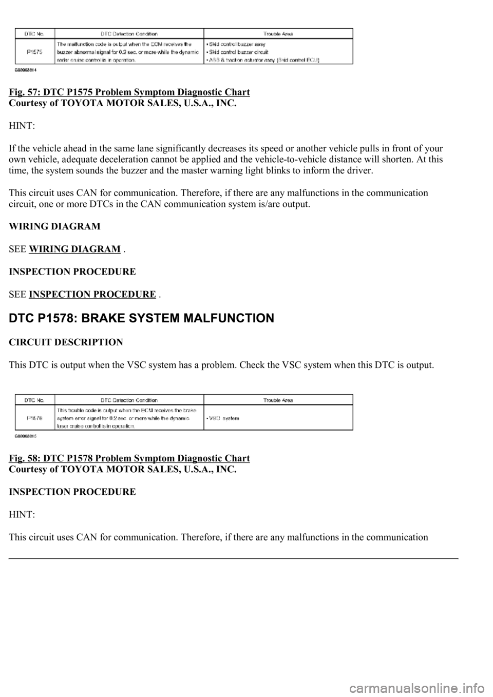
Fig. 57: DTC P1575 Problem Symptom Diagnostic Chart
Courtesy of TOYOTA MOTOR SALES, U.S.A., INC.
HINT:
If the vehicle ahead in the same lane significantly decreases its speed or another vehicle pulls in front of your
own vehicle, adequate deceleration cannot be applied and the vehicle-to-vehicle distance will shorten. At this
time, the system sounds the buzzer and the master warning light blinks to inform the driver.
This circuit uses CAN for communication. Therefore, if there are any malfunctions in the communication
circuit, one or more DTCs in the CAN communication system is/are output.
WIRING DIAGRAM
SEE WIRING DIAGRAM
.
INSPECTION PROCEDURE
SEE INSPECTION PROCEDURE
.
CIRCUIT DESCRIPTION
This DTC is output when the VSC system has a problem. Check the VSC system when this DTC is output.
Fig. 58: DTC P1578 Problem Symptom Diagnostic Chart
Courtesy of TOYOTA MOTOR SALES, U.S.A., INC.
INSPECTION PROCEDURE
HINT:
This circuit uses CAN for communication. Therefore, if there are an
y malfunctions in the communication
Page 2627 of 4500
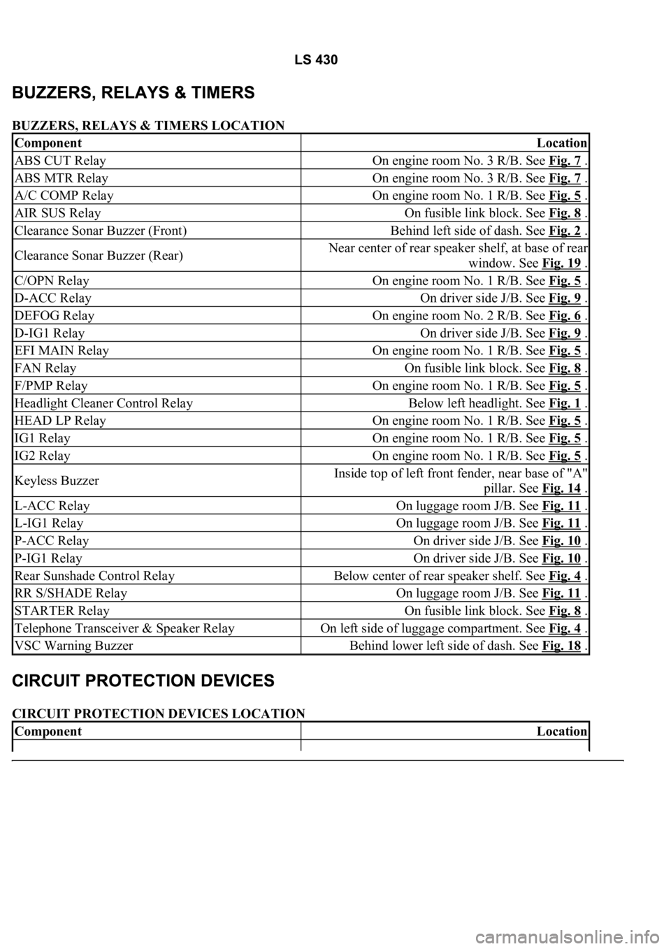
BUZZERS, RELAYS & TIMERS LOCATION
CIRCUIT PROTECTION DEVICES LOCATION
ComponentLocation
ABS CUT RelayOn engine room No. 3 R/B. See Fig. 7 .
ABS MTR RelayOn engine room No. 3 R/B. See Fig. 7 .
A/C COMP RelayOn engine room No. 1 R/B. See Fig. 5 .
AIR SUS RelayOn fusible link block. See Fig. 8 .
Clearance Sonar Buzzer (Front)Behind left side of dash. See Fig. 2 .
Clearance Sonar Buzzer (Rear)Near center of rear speaker shelf, at base of rear
window. See Fig. 19
.
C/OPN RelayOn engine room No. 1 R/B. See Fig. 5 .
D-ACC RelayOn driver side J/B. See Fig. 9 .
DEFOG RelayOn engine room No. 2 R/B. See Fig. 6 .
D-IG1 RelayOn driver side J/B. See Fig. 9 .
EFI MAIN RelayOn engine room No. 1 R/B. See Fig. 5 .
FAN RelayOn fusible link block. See Fig. 8 .
F/PMP RelayOn engine room No. 1 R/B. See Fig. 5 .
Headlight Cleaner Control RelayBelow left headlight. See Fig. 1 .
HEAD LP RelayOn engine room No. 1 R/B. See Fig. 5 .
IG1 RelayOn engine room No. 1 R/B. See Fig. 5 .
IG2 RelayOn engine room No. 1 R/B. See Fig. 5 .
Keyless BuzzerInside top of left front fender, near base of "A"
pillar. See Fig. 14
.
L-ACC RelayOn luggage room J/B. See Fig. 11 .
L-IG1 RelayOn luggage room J/B. See Fig. 11 .
P-ACC RelayOn driver side J/B. See Fig. 10 .
P-IG1 RelayOn driver side J/B. See Fig. 10 .
Rear Sunshade Control RelayBelow center of rear speaker shelf. See Fig. 4 .
RR S/SHADE RelayOn luggage room J/B. See Fig. 11 .
STARTER RelayOn fusible link block. See Fig. 8 .
Telephone Transceiver & Speaker RelayOn left side of luggage compartment. See Fig. 4 .
VSC Warning BuzzerBehind lower left side of dash. See Fig. 18 .
ComponentLocation