LEXUS LS430 2003 Factory Service Manual
LS430 2003
LEXUS
LEXUS
https://www.carmanualsonline.info/img/36/57050/w960_57050-0.png
LEXUS LS430 2003 Factory Service Manual
Page 2925 of 4500
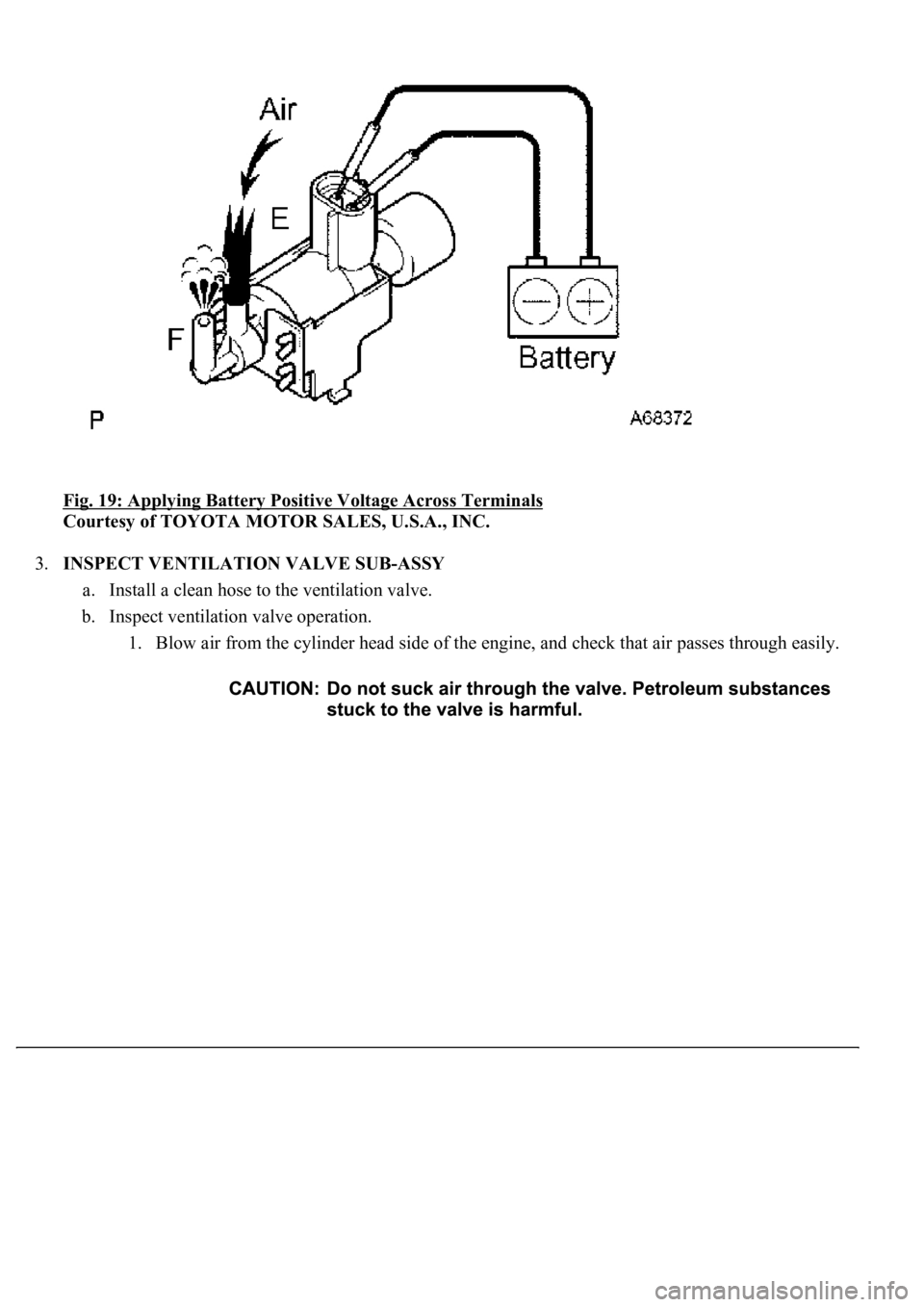
Fig. 19: Applying Battery Positive Voltage Across Terminals
Courtesy of TOYOTA MOTOR SALES, U.S.A., INC.
3.INSPECT VENTILATION VALVE SUB-ASSY
a. Install a clean hose to the ventilation valve.
b. Inspect ventilation valve operation.
1. Blow air from the cylinder head side of the engine, and check that air passes through easily.
Page 2964 of 4500
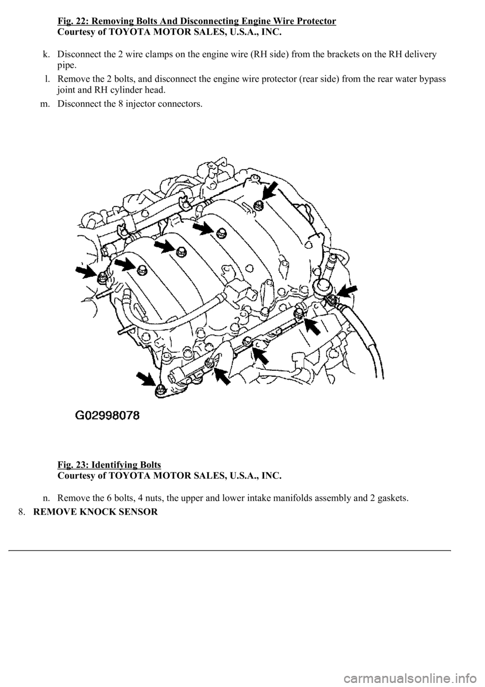
Fig. 22: Removing Bolts And Disconnecting Engine Wire Protector
Courtesy of TOYOTA MOTOR SALES, U.S.A., INC.
k. Disconnect the 2 wire clamps on the engine wire (RH side) from the brackets on the RH delivery
pipe.
l. Remove the 2 bolts, and disconnect the engine wire protector (rear side) from the rear water bypass
joint and RH cylinder head.
m. Disconnect the 8 injector connectors.
Fig. 23: Identifying Bolts
Courtesy of TOYOTA MOTOR SALES, U.S.A., INC.
n. Remove the 6 bolts, 4 nuts, the upper and lower intake manifolds assembly and 2 gaskets.
8.REMOVE KNOCK SENSOR
Page 2967 of 4500
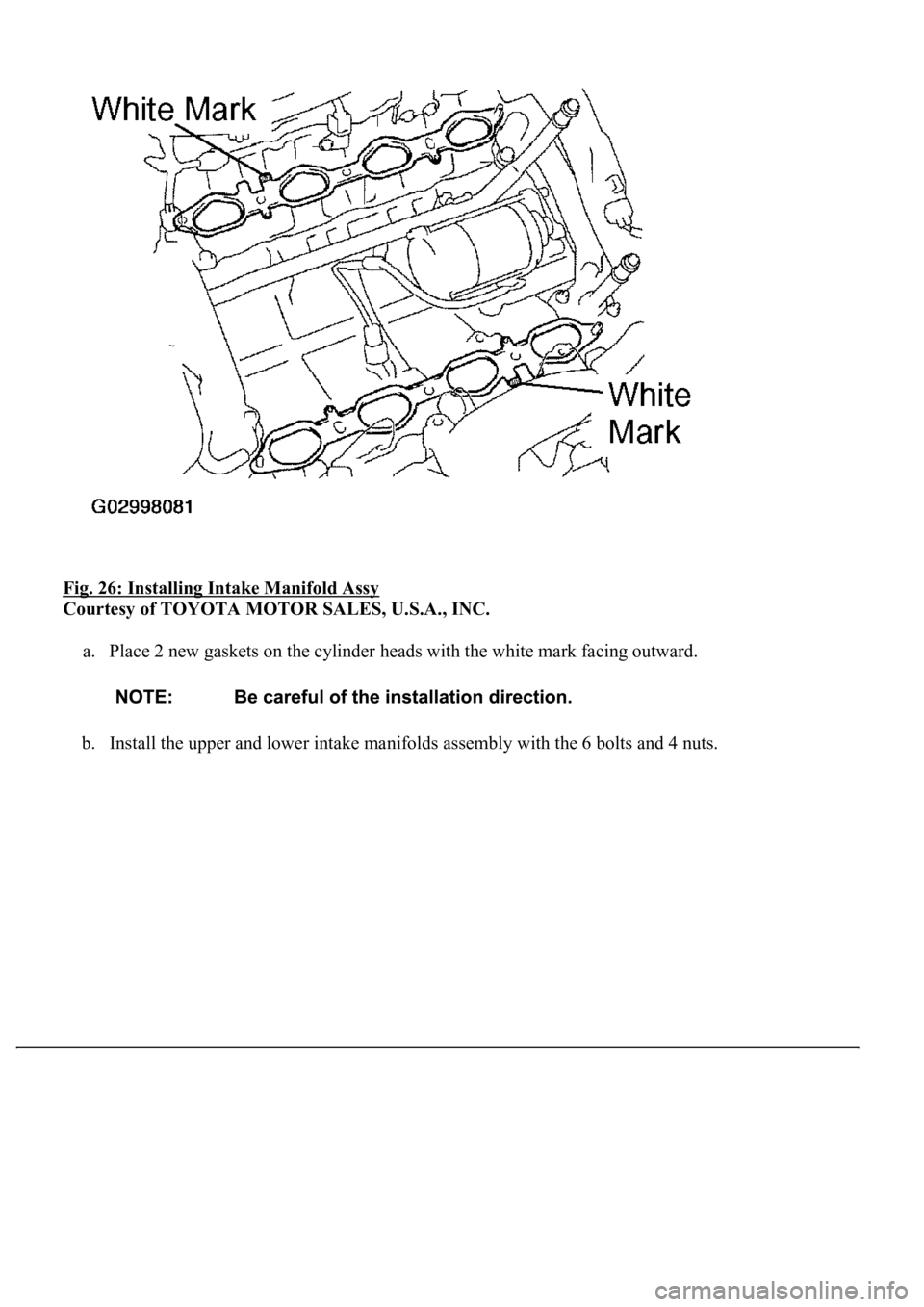
Fig. 26: Installing Intake Manifold Assy
Courtesy of TOYOTA MOTOR SALES, U.S.A., INC.
a. Place 2 new gaskets on the cylinder heads with the white mark facing outward.
b. Install the upper and lower intake manifolds assembly with the 6 bolts and 4 nuts.
Page 3033 of 4500
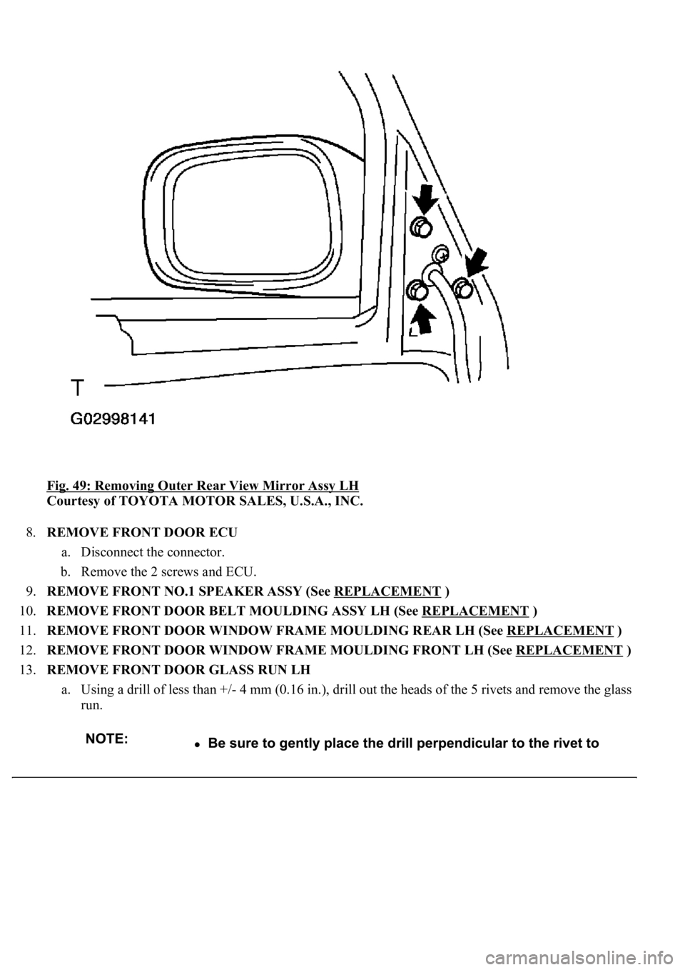
Fig. 49: Removing Outer Rear View Mirror Assy LH
Courtesy of TOYOTA MOTOR SALES, U.S.A., INC.
8.REMOVE FRONT DOOR ECU
a. Disconnect the connector.
b. Remove the 2 screws and ECU.
9.REMOVE FRONT NO.1 SPEAKER ASSY (See REPLACEMENT
)
10.REMOVE FRONT DOOR BELT MOULDING ASSY LH (See REPLACEMENT
)
11.REMOVE FRONT DOOR WINDOW FRAME MOULDING REAR LH (See REPLACEMENT
)
12.REMOVE FRONT DOOR WINDOW FRAME MOULDING FRONT LH (See REPLACEMENT
)
13.REMOVE FRONT DOOR GLASS RUN LH
a. Using a drill of less than +/- 4 mm (0.16 in.), drill out the heads of the 5 rivets and remove the glass
run.
Page 3091 of 4500
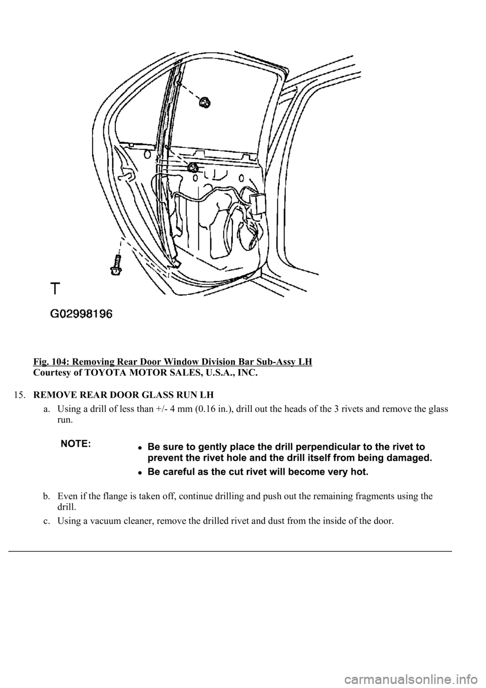
<0029004c004a00110003001400130017001d000300350048005000520059004c0051004a00030035004800440055000300270052005200550003003a004c005100470052005a00030027004c0059004c0056004c0052005100030025004400550003003600
580045[-Assy LH
Courtesy of TOYOTA MOTOR SALES, U.S.A., INC.
15.REMOVE REAR DOOR GLASS RUN LH
a. Using a drill of less than +/- 4 mm (0.16 in.), drill out the heads of the 3 rivets and remove the glass
run.
b. Even if the flange is taken off, continue drilling and push out the remaining fragments using the
drill.
c. Using a vacuum cleaner, remove the drilled rivet and dust from the inside of the door.
Page 3290 of 4500
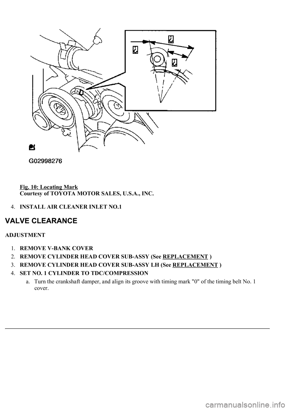
Fig. 10: Locating Mark
Courtesy of TOYOTA MOTOR SALES, U.S.A., INC.
4.INSTALL AIR CLEANER INLET NO.1
ADJUSTMENT
1.REMOVE V-BANK COVER
2.REMOVE CYLINDER HEAD COVER SUB-ASSY (See REPLACEMENT
)
3.REMOVE CYLINDER HEAD COVER SUB-ASSY LH (See REPLACEMENT
)
4.SET NO. 1 CYLINDER TO TDC/COMPRESSION
a. Turn the crankshaft damper, and align its groove with timing mark "0" of the timing belt No. 1
cover.
Page 3298 of 4500
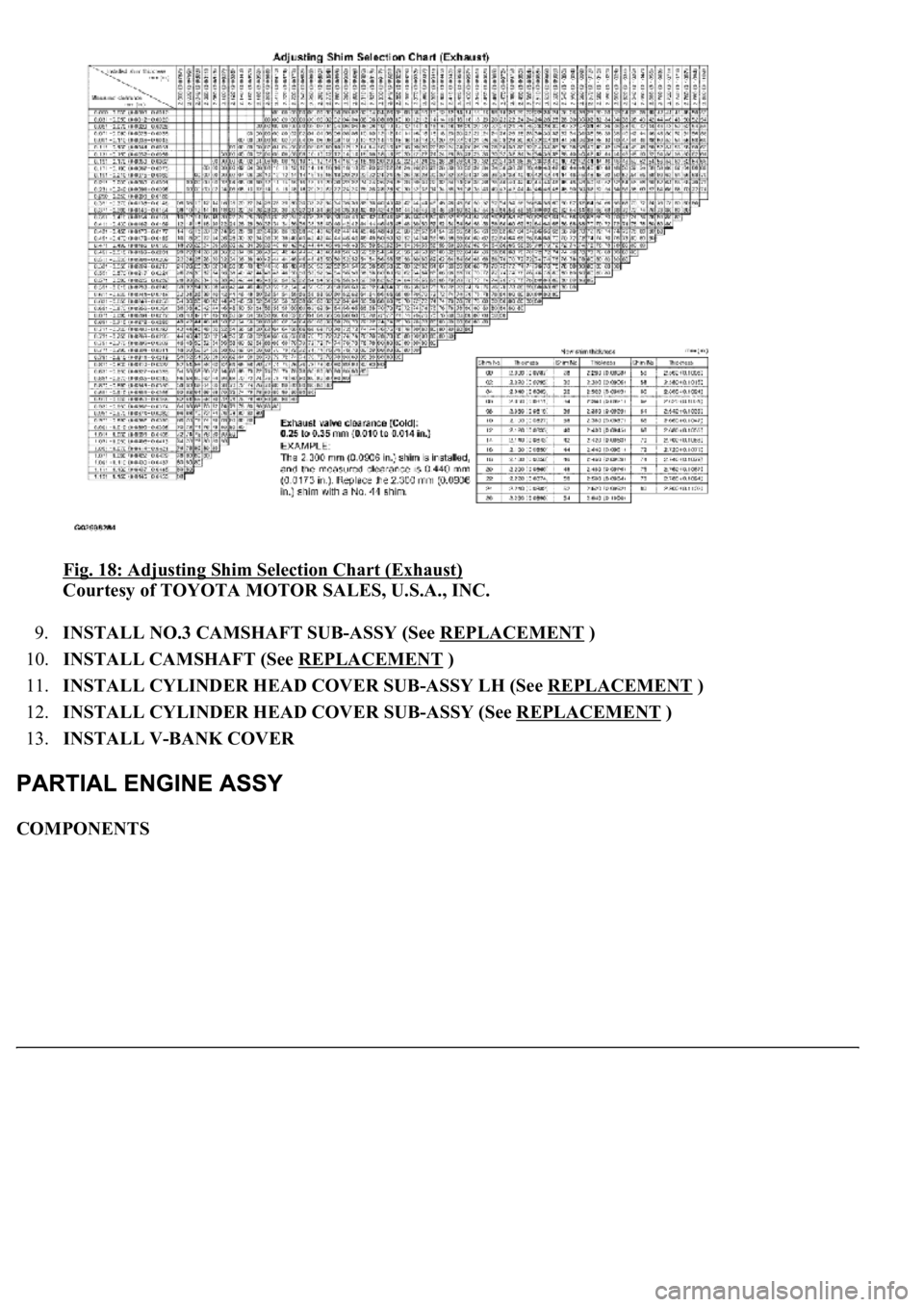
Fig. 18: Adjusting Shim Selection Chart (Exhaust)
Courtesy of TOYOTA MOTOR SALES, U.S.A., INC.
9.INSTALL NO.3 CAMSHAFT SUB-ASSY (See REPLACEMENT
)
10.INSTALL CAMSHAFT (See REPLACEMENT
)
11.INSTALL CYLINDER HEAD COVER SUB-ASSY LH (See REPLACEMENT
)
12.INSTALL CYLINDER HEAD COVER SUB-ASSY (See REPLACEMENT
)
13.INSTALL V-BANK COVER
COMPONENTS
Page 3314 of 4500
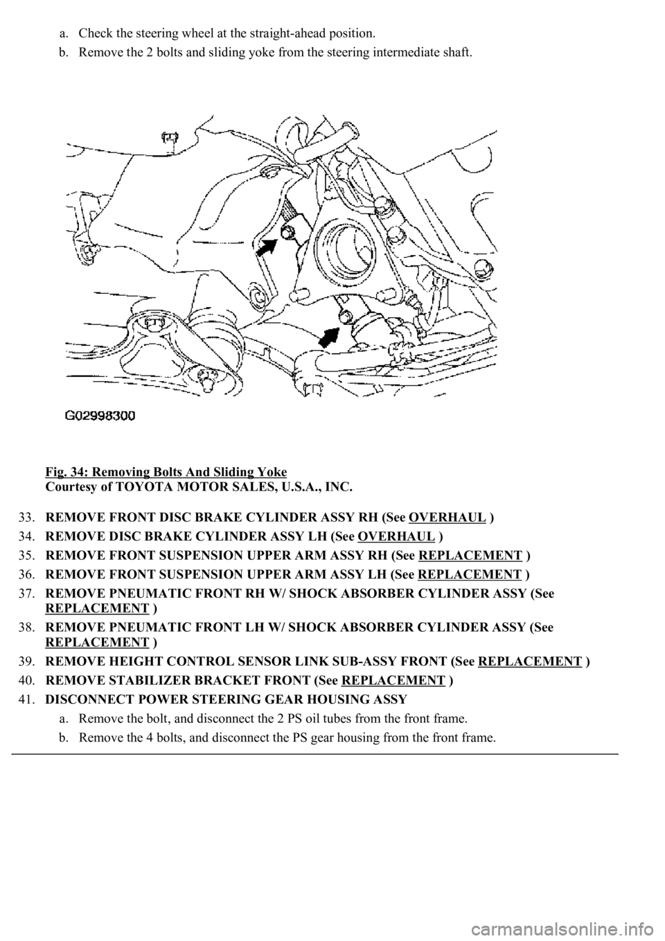
a. Check the steering wheel at the straight-ahead position.
b. Remove the 2 bolts and sliding yoke from the steering intermediate shaft.
Fig. 34: Removing Bolts And Sliding Yoke
Courtesy of TOYOTA MOTOR SALES, U.S.A., INC.
33.REMOVE FRONT DISC BRAKE CYLINDER ASSY RH (See OVERHAUL
)
34.REMOVE DISC BRAKE CYLINDER ASSY LH (See OVERHAUL
)
35.REMOVE FRONT SUSPENSION UPPER ARM ASSY RH (See REPLACEMENT
)
36.REMOVE FRONT SUSPENSION UPPER ARM ASSY LH (See REPLACEMENT
)
37.REMOVE PNEUMATIC FRONT RH W/ SHOCK ABSORBER CYLINDER ASSY (See
REPLACEMENT
)
38.REMOVE PNEUMATIC FRONT LH W/ SHOCK ABSORBER CYLINDER ASSY (See
REPLACEMENT
)
39.REMOVE HEIGHT CONTROL SENSOR LINK SUB-ASSY FRONT (See REPLACEMENT
)
40.REMOVE STABILIZER BRACKET FRONT (See REPLACEMENT
)
41.DISCONNECT POWER STEERING GEAR HOUSING ASSY
a. Remove the bolt, and disconnect the 2 PS oil tubes from the front frame.
b. Remove the 4 bolts, and disconnect the PS gear housing from the front frame.
Page 3321 of 4500
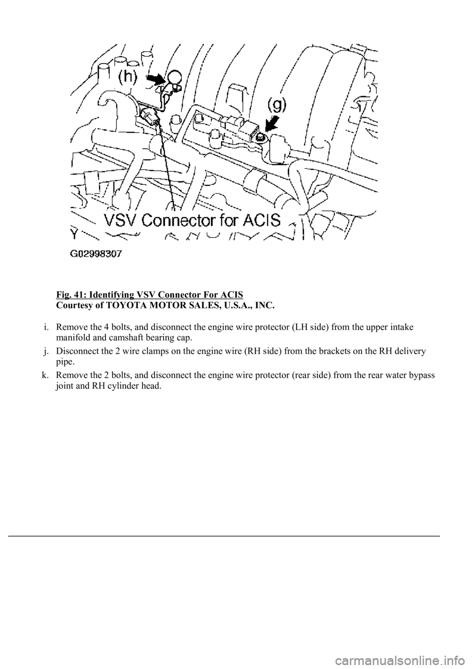
Fig. 41: Identifying VSV Connector For ACIS
Courtesy of TOYOTA MOTOR SALES, U.S.A., INC.
i. Remove the 4 bolts, and disconnect the engine wire protector (LH side) from the upper intake
manifold and camshaft bearing cap.
j. Disconnect the 2 wire clamps on the engine wire (RH side) from the brackets on the RH delivery
pipe.
k. Remove the 2 bolts, and disconnect the engine wire protector (rear side) from the rear water bypass
joint and RH cylinder head.
Page 3323 of 4500
Fig. 42: Disconnecting Engine Wire Protector (LH Side) From Upper Intake Manifold
Courtesy of TOYOTA MOTOR SALES, U.S.A., INC.
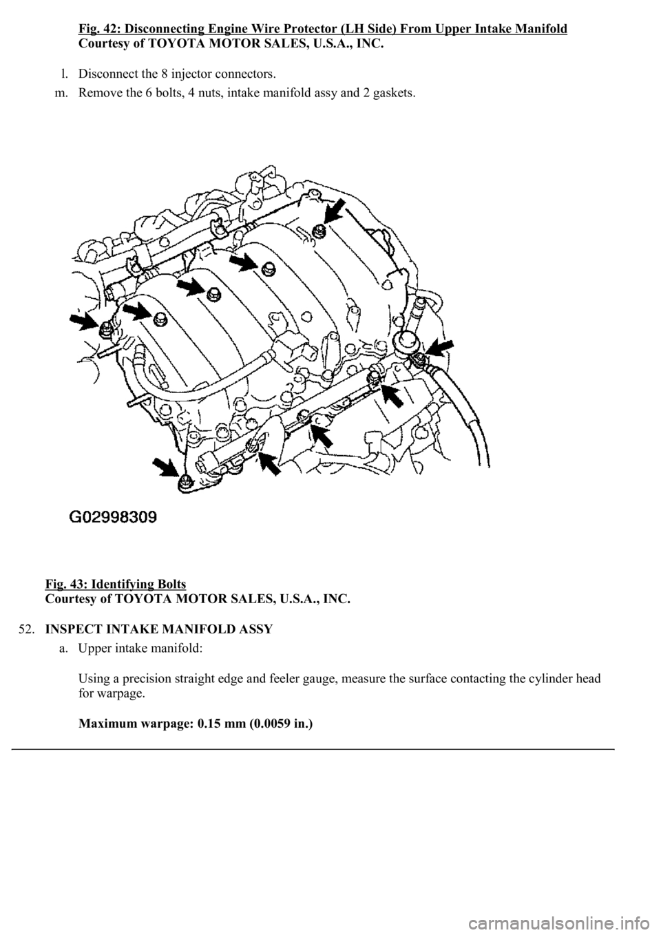
l. Disconnect the 8 injector connectors.
m. Remove the 6 bolts, 4 nuts, intake manifold assy and 2 gaskets.
Fig. 43: Identifying Bolts
Courtesy of TOYOTA MOTOR SALES, U.S.A., INC.
52.INSPECT INTAKE MANIFOLD ASSY
a. Upper intake manifold:
Using a precision straight edge and feeler gauge, measure the surface contacting the cylinder head
for warpage.
Maximum warpage: 0.15 mm (0.0059 in.)