LEXUS LS430 2003 Factory Repair Manual
LS430 2003
LEXUS
LEXUS
https://www.carmanualsonline.info/img/36/57050/w960_57050-0.png
LEXUS LS430 2003 Factory Repair Manual
Page 4339 of 4500
4.REMOVE OIL LEVEL GAGE SUB-ASSY (See step 8 in REPLACEMENT )
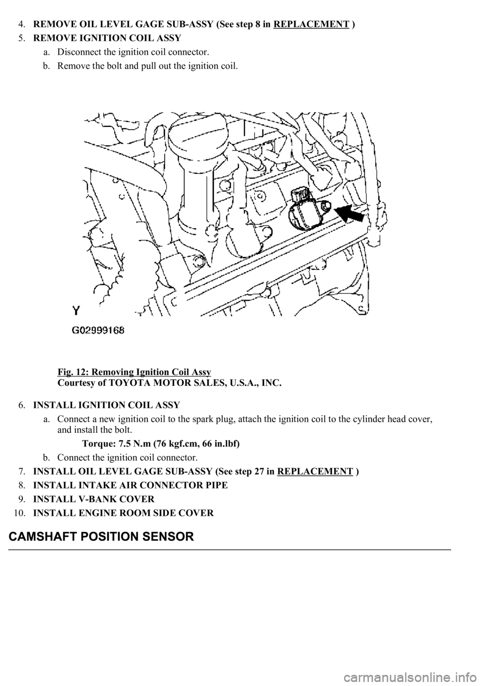
5.REMOVE IGNITION COIL ASSY
a. Disconnect the ignition coil connector.
b. Remove the bolt and pull out the ignition coil.
Fig. 12: Removing Ignition Coil Assy
Courtesy of TOYOTA MOTOR SALES, U.S.A., INC.
6.INSTALL IGNITION COIL ASSY
a. Connect a new ignition coil to the spark plug, attach the ignition coil to the cylinder head cover,
and install the bolt.
Torque: 7.5 N.m (76 kgf.cm, 66 in.lbf)
b. Connect the ignition coil connector.
7.INSTALL OIL LEVEL GAGE SUB-ASSY (See step 27 in REPLACEMENT
)
8.INSTALL INTAKE AIR CONNECTOR PIPE
9.INSTALL V-BANK COVER
10.INSTALL ENGINE ROOM SIDE COVER
Page 4340 of 4500
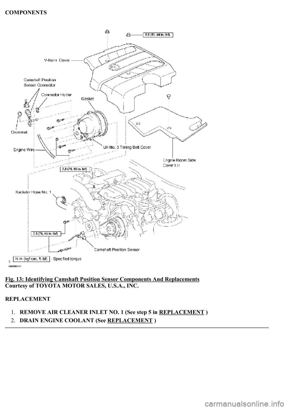
COMPONENTS
Fig. 13: Identifying Camshaft Position Sensor Components And Replacements
Courtesy of TOYOTA MOTOR SALES, U.S.A., INC.
REPLACEMENT
1.REMOVE AIR CLEANER INLET NO. 1 (See step 5 in REPLACEMENT
)
2.DRAIN ENGINE COOLANT (See REPLACEMENT
)
Page 4341 of 4500
3.REMOVE V-BANK COVER
4.REMOVE ENGINE ROOM SIDE COVER
5.DISCONNECT RADIATOR HOSE NO. 1
6.REMOVE TIMING BELT COVER SUB-ASSY NO. 3 LH (See step 18 in REPLACEMENT
)
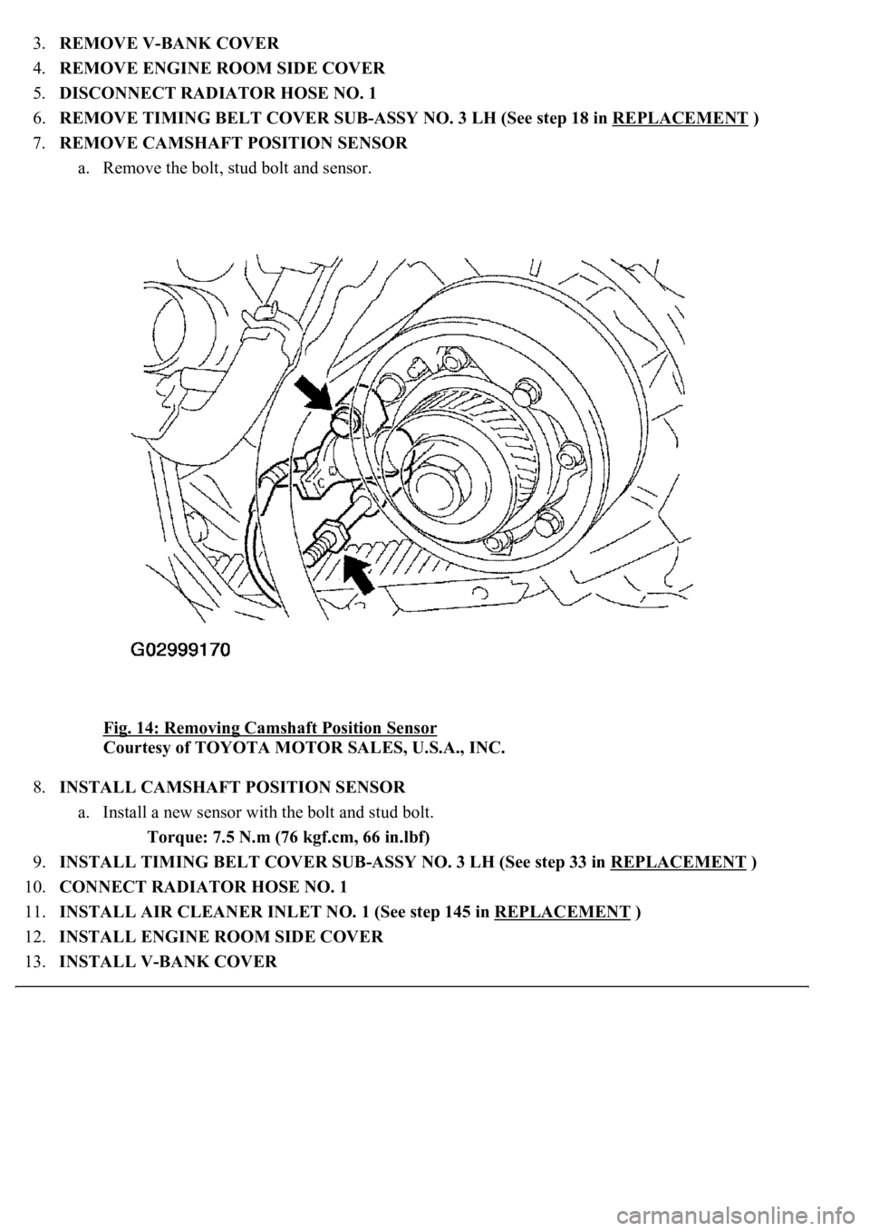
7.REMOVE CAMSHAFT POSITION SENSOR
a. Remove the bolt, stud bolt and sensor.
Fig. 14: Removing Camshaft Position Sensor
Courtesy of TOYOTA MOTOR SALES, U.S.A., INC.
8.INSTALL CAMSHAFT POSITION SENSOR
a. Install a new sensor with the bolt and stud bolt.
Torque: 7.5 N.m (76 kgf.cm, 66 in.lbf)
9.INSTALL TIMING BELT COVER SUB-ASSY NO. 3 LH (See step 33 in REPLACEMENT
)
10.CONNECT RADIATOR HOSE NO. 1
11.INSTALL AIR CLEANER INLET NO. 1 (See step 145 in REPLACEMENT
)
12.INSTALL ENGINE ROOM SIDE COVER
13.INSTALL V-BANK COVER
Page 4342 of 4500
14.REFILL ENGINE COOLANT (See REPLACEMENT )
15.WARM UP ENGINE
16.CHECK FOR ENGINE COOLANT LEAKS
COMPONENTS
Page 4343 of 4500
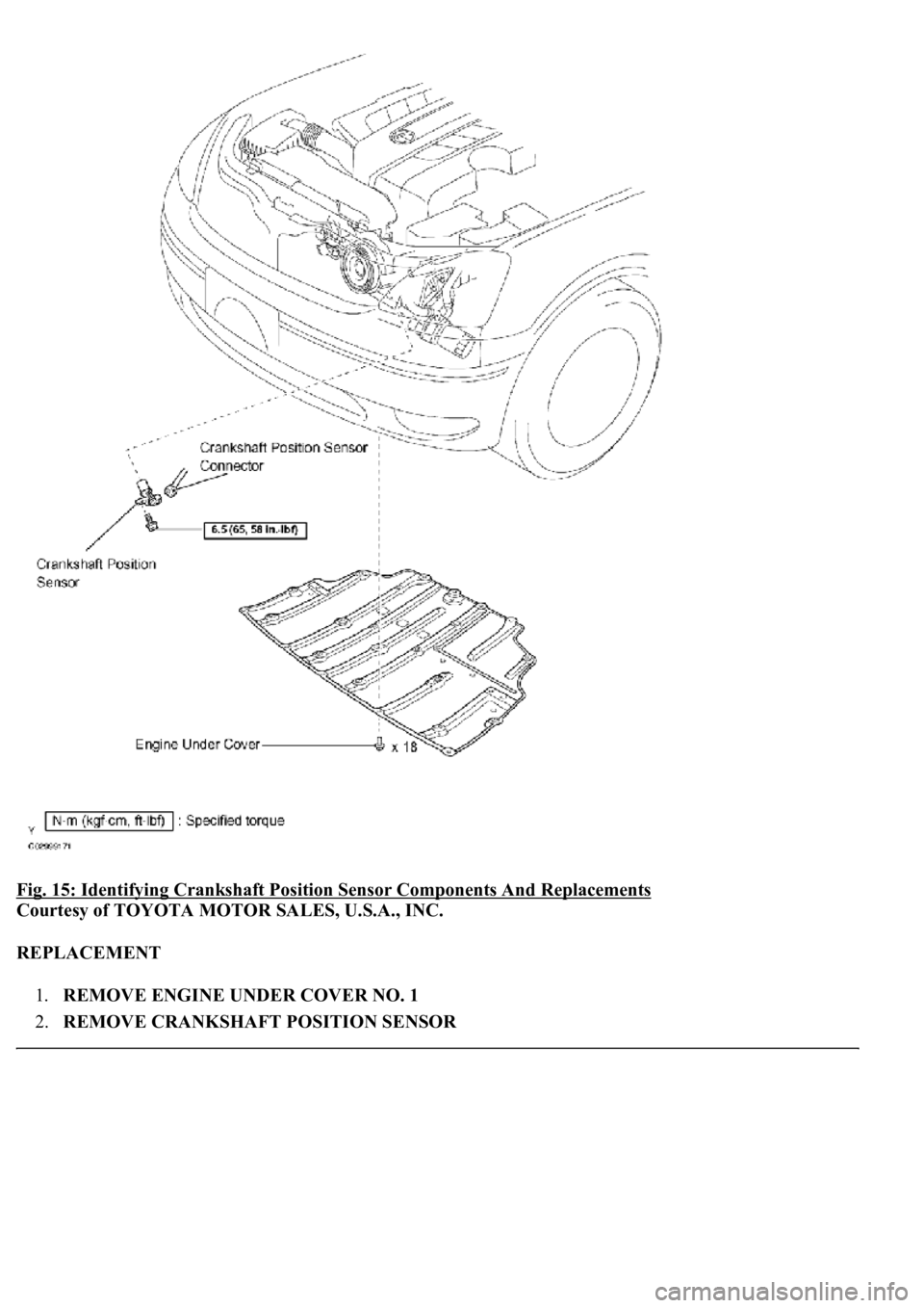
Fig. 15: Identifying Crankshaft Position Sensor Components And Replacements
Courtesy of TOYOTA MOTOR SALES, U.S.A., INC.
REPLACEMENT
1.REMOVE ENGINE UNDER COVER NO. 1
2.REMOVE CRANKSHAFT POSITION SENSOR
Page 4345 of 4500
4.INSTALL ENGINE UNDER COVER NO. 1
Page 4402 of 4500
Fig. 3: Inspecting Intake Air Control Function
Courtesy of TOYOTA MOTOR SALES, U.S.A., INC.
a. Remove the V-bank cover.
b. Connect the hand-held tester (with CAN VIM) to the DLC3.
c. Perform the ACTIVE TEST, and then check that the actuator rod operates.
d. Start the engine.
e. Check that the VSV for IAC valve in ON (seal) under these conditions.
Depressing the accelerator pedal to a throttle valve opening angle of 60 degrees.
Racing the engine above 4,700 rpm.
f. Check that the VSV for IAC valve is OFF (vent) under these conditions.
The engine is idling.
Releasing the accelerator pedal while under the 2 conditions in step (e).
If the result is not as specified, inspect the IAC valve, vacuum tank and VSV for normal operation.
Replace malfunctioning parts as necessary.
INSPECTION
1.INSPECT INTAKE AIR CONTROL VALVE ACTUATOR
a. Connect the MITYVAC (han
d-held vacuum pump) to the actuator.
Page 4407 of 4500
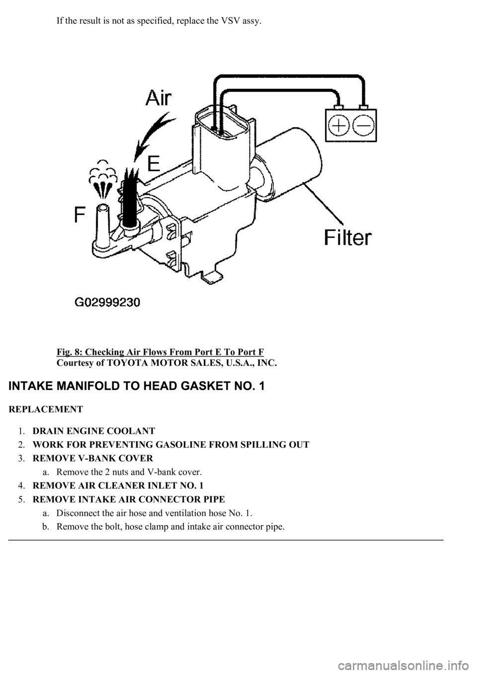
If the result is not as specified, replace the VSV assy.
Fig. 8: Checking Air Flows From Port E To Port F
Courtesy of TOYOTA MOTOR SALES, U.S.A., INC.
REPLACEMENT
1.DRAIN ENGINE COOLANT
2.WORK FOR PREVENTING GASOLINE FROM SPILLING OUT
3.REMOVE V-BANK COVER
a. Remove the 2 nuts and V-bank cover.
4.REMOVE AIR CLEANER INLET NO. 1
5.REMOVE INTAKE AIR CONNECTOR PIPE
a. Disconnect the air hose and ventilation hose No. 1.
b. Remove the bolt, hose clamp and intake air connector pipe.
Page 4412 of 4500
a. Install the cover bracket with the bolt.
Torque: 7.5 N.m (76 kgf.cm, 66 in.lbf)
23.INSTALL THROTTLE BODY ASSY
a. Install the throttle body with the 2 bolts and 2 nuts.
b. Connect the water by-pass hose.
c. Connect the PCV hose.
d. Connect the connector to the throttle body.
24.INSTALL INTAKE AIR CONNECTOR PIPE
a. Install the intake air connector pipe with the bolt and hose clamp.
Torque:
4.0 N.m (40 kgf.cm, 35 in.lbf) for hose clamp
5.0 N.m (50 kgf.cm, 44 in.lbf) for bolt
b. Connect the air hose and ventilation hose No. 1 together.
25.INSTALL AIR CLEANER INLET NO. 1
26.INSPECT FUEL PUMP OPERATION AND CHECK FOR FUEL LEAKS
27.INSTALL V-BANK COVER
a. Install the V-bank cover with the 2 nuts.
Torque: 5.0 N.m (50 kgf.cm, 44 in.lbf)
28.REFILL ENGINE COOLANT
29.CHECK FOR ENGINE COOLANT LEAKS
a. Check for engine coolant leaks.
If leaks are present, find the leak and repair or replace parts as necessar
y.
Page 4491 of 4500
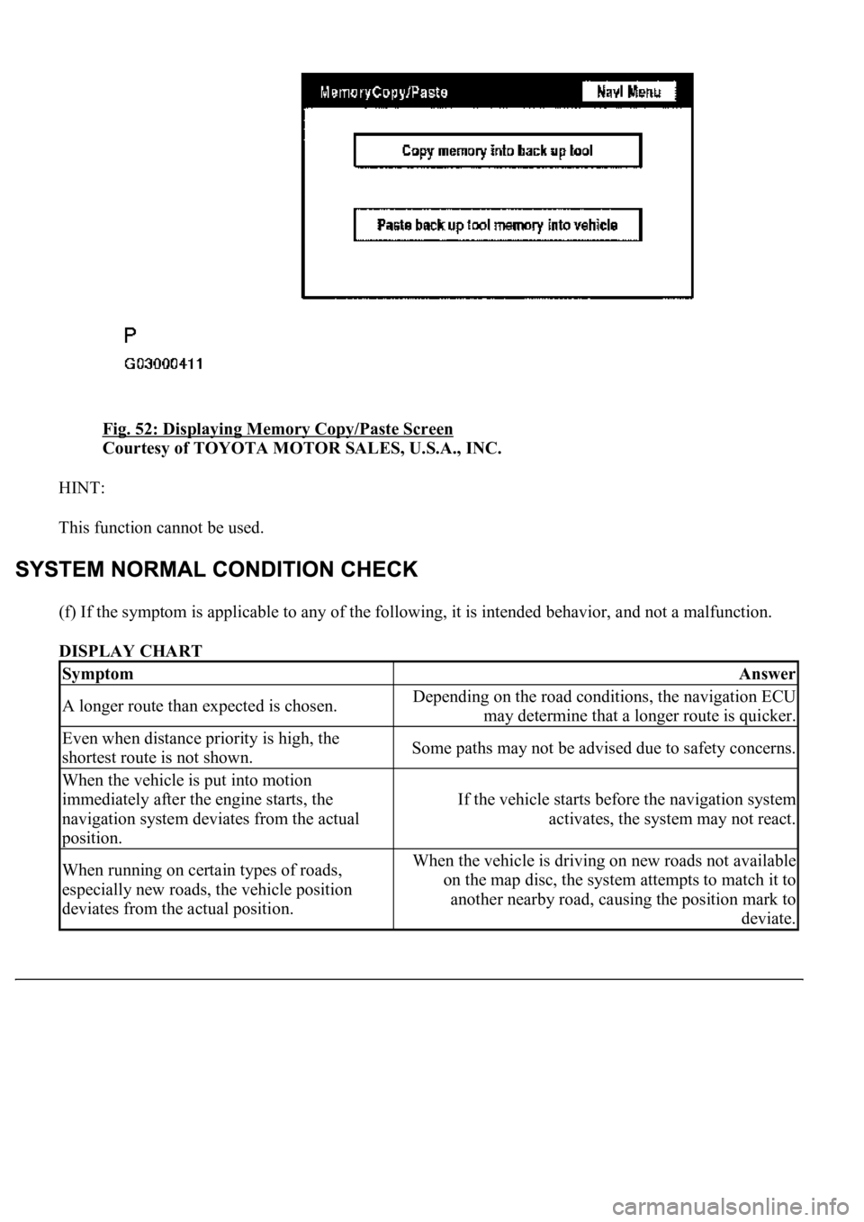
Fig. 52: Displaying Memory Copy/Paste Screen
Courtesy of TOYOTA MOTOR SALES, U.S.A., INC.
HINT:
This function cannot be used.
(f) If the symptom is applicable to any of the following, it is intended behavior, and not a malfunction.
DISPLAY CHART
SymptomAnswer
A longer route than expected is chosen.Depending on the road conditions, the navigation ECU
may determine that a longer route is quicker.
Even when distance priority is high, the
shortest route is not shown.Some paths may not be advised due to safety concerns.
When the vehicle is put into motion
immediately after the engine starts, the
navigation system deviates from the actual
position.
If the vehicle starts before the navigation system
activates, the system may not react.
When running on certain types of roads,
especially new roads, the vehicle position
deviates from the actual position.When the vehicle is driving on new roads not available
on the map disc, the system attempts to match it to
another nearby road, causing the position mark to
deviate.
