LEXUS LS430 2003 Factory Service Manual
LS430 2003
LEXUS
LEXUS
https://www.carmanualsonline.info/img/36/57050/w960_57050-0.png
LEXUS LS430 2003 Factory Service Manual
Page 3290 of 4500
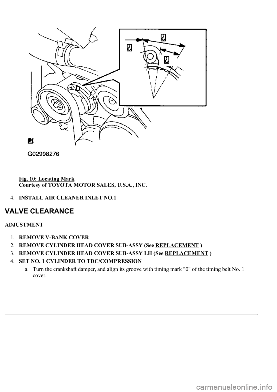
Fig. 10: Locating Mark
Courtesy of TOYOTA MOTOR SALES, U.S.A., INC.
4.INSTALL AIR CLEANER INLET NO.1
ADJUSTMENT
1.REMOVE V-BANK COVER
2.REMOVE CYLINDER HEAD COVER SUB-ASSY (See REPLACEMENT
)
3.REMOVE CYLINDER HEAD COVER SUB-ASSY LH (See REPLACEMENT
)
4.SET NO. 1 CYLINDER TO TDC/COMPRESSION
a. Turn the crankshaft damper, and align its groove with timing mark "0" of the timing belt No. 1
cover.
Page 3319 of 4500
2. Turn the crankshaft damper bolt to gain access to each bolt.
3. Hold the crankshaft damper bolt with a wrench, and remove the 6 bolts.
b. Remove the 10 bolts and ground strap.
c. Remove the transmission together with the torque converter clutch from the engine.
Fig. 39: Removing Flywheel Housing Under Cover
Courtesy of TOYOTA MOTOR SALES, U.S.A., INC.
48.REMOVE DRIVE PLATE & RING GEAR SUB-ASSY
a. Remove the 8 bolts, rear spacer, ring gear and front spacer.
49.INSTALL ENGINE STAND
50.REMOVE THROTTLE BODY ASSY (See REPLACEMENT
)
51.REMOVE INTAKE MANIFOLD ASSY
a. Disconnect the VSV connector for EVAP.
b. Disconnect the EVAP hose from the VSV for EVAP.
c. Remove the bolt, disconnect the VSV for EVAP from the upper intake manifold.
d. Remove the bolt and V-bank cover bracket No. 2.
e. Remove the bolt and V-
bank cover bracket No. 3.
Page 3364 of 4500
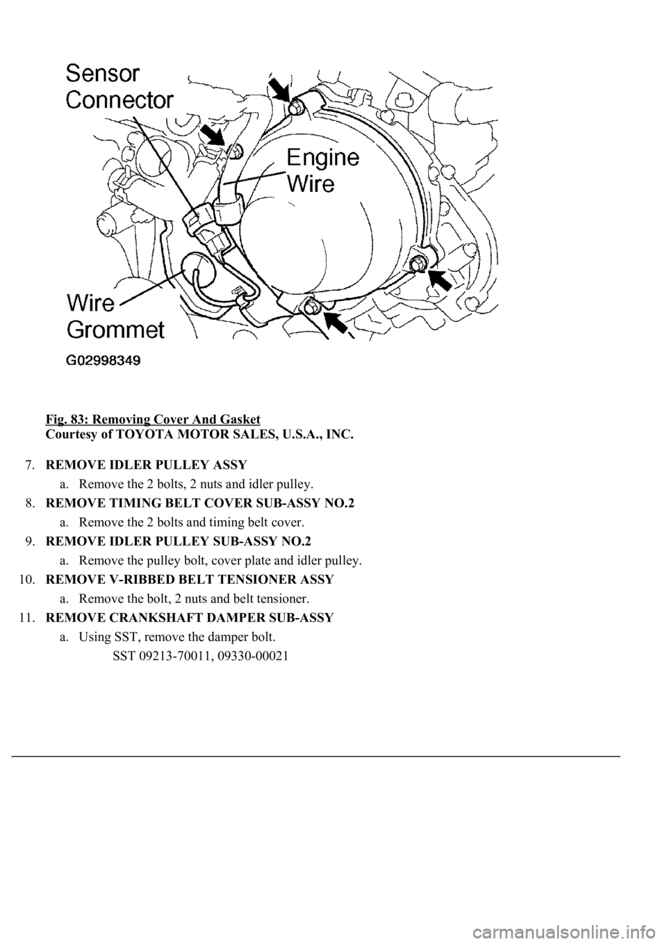
Fig. 83: Removing Cover And Gasket
Courtesy of TOYOTA MOTOR SALES, U.S.A., INC.
7.REMOVE IDLER PULLEY ASSY
a. Remove the 2 bolts, 2 nuts and idler pulley.
8.REMOVE TIMING BELT COVER SUB-ASSY NO.2
a. Remove the 2 bolts and timing belt cover.
9.REMOVE IDLER PULLEY SUB-ASSY NO.2
a. Remove the pulley bolt, cover plate and idler pulley.
10.REMOVE V-RIBBED BELT TENSIONER ASSY
a. Remove the bolt, 2 nuts and belt tensioner.
11.REMOVE CRANKSHAFT DAMPER SUB-ASSY
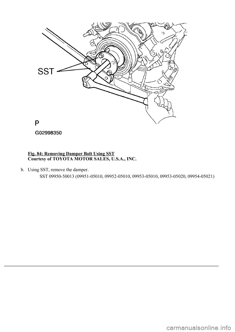
a. Using SST, remove the damper bolt.
SST 09213-70011, 09330-00021
Page 3365 of 4500
Fig. 84: Removing Damper Bolt Using SST
Courtesy of TOYOTA MOTOR SALES, U.S.A., INC.
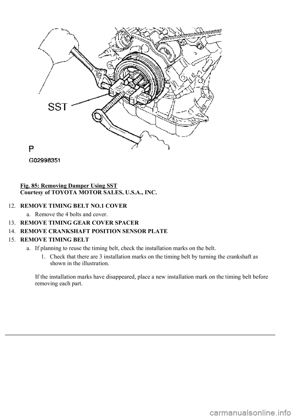
b. Using SST, remove the damper.
<00360036003700030013001c001c001800130010001800130013001400160003000b0013001c001c00180014001000130018001300140013000f00030013001c001c00180015001000130018001300140013000f00030013001c001c001800160010001300
18001300140013000f00030013001c001c0018001600100013[5020, 09954-05021)
Page 3366 of 4500
Fig. 85: Removing Damper Using SST
Courtesy of TOYOTA MOTOR SALES, U.S.A., INC.
12.REMOVE TIMING BELT NO.1 COVER
a. Remove the 4 bolts and cover.
13.REMOVE TIMING GEAR COVER SPACER
14.REMOVE CRANKSHAFT POSITION SENSOR PLATE
15.REMOVE TIMING BELT
a. If planning to reuse the timing belt, check the installation marks on the belt.
1. Check that there are 3 installation marks on the timing belt by turning the crankshaft as
shown in the illustration.
If the installation marks have disappeared, place a new installation mark on the timing belt before
removing each part.
Page 3367 of 4500
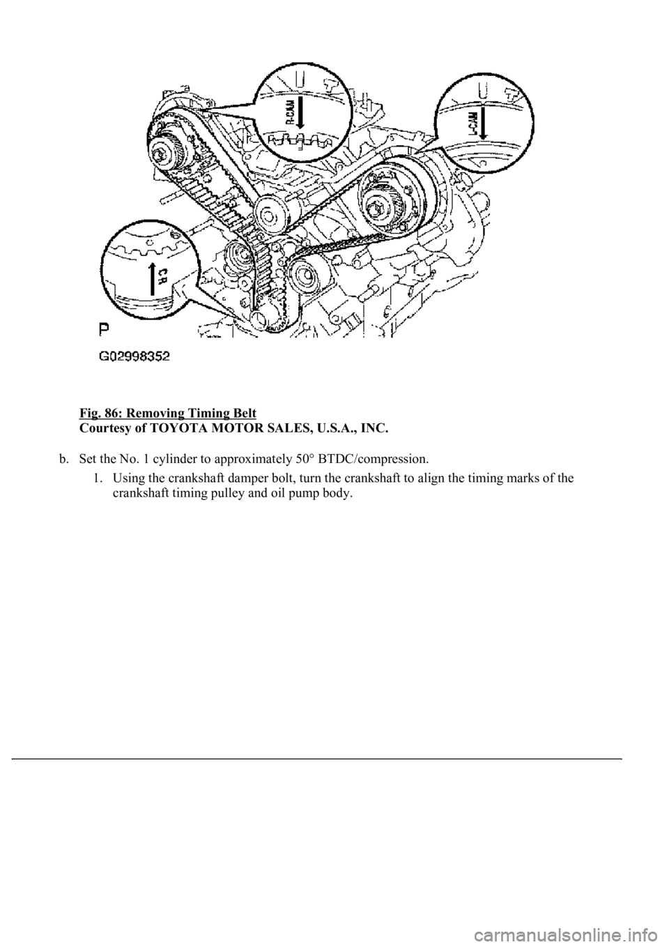
Fig. 86: Removing Timing Belt
Courtesy of TOYOTA MOTOR SALES, U.S.A., INC.
b. Set the No. 1 cylinder to approximately 50° BTDC/compression.
1. Using the crankshaft damper bolt, turn the crankshaft to align the timing marks of the
crankshaft timing pulley and oil pump body.
Page 3369 of 4500
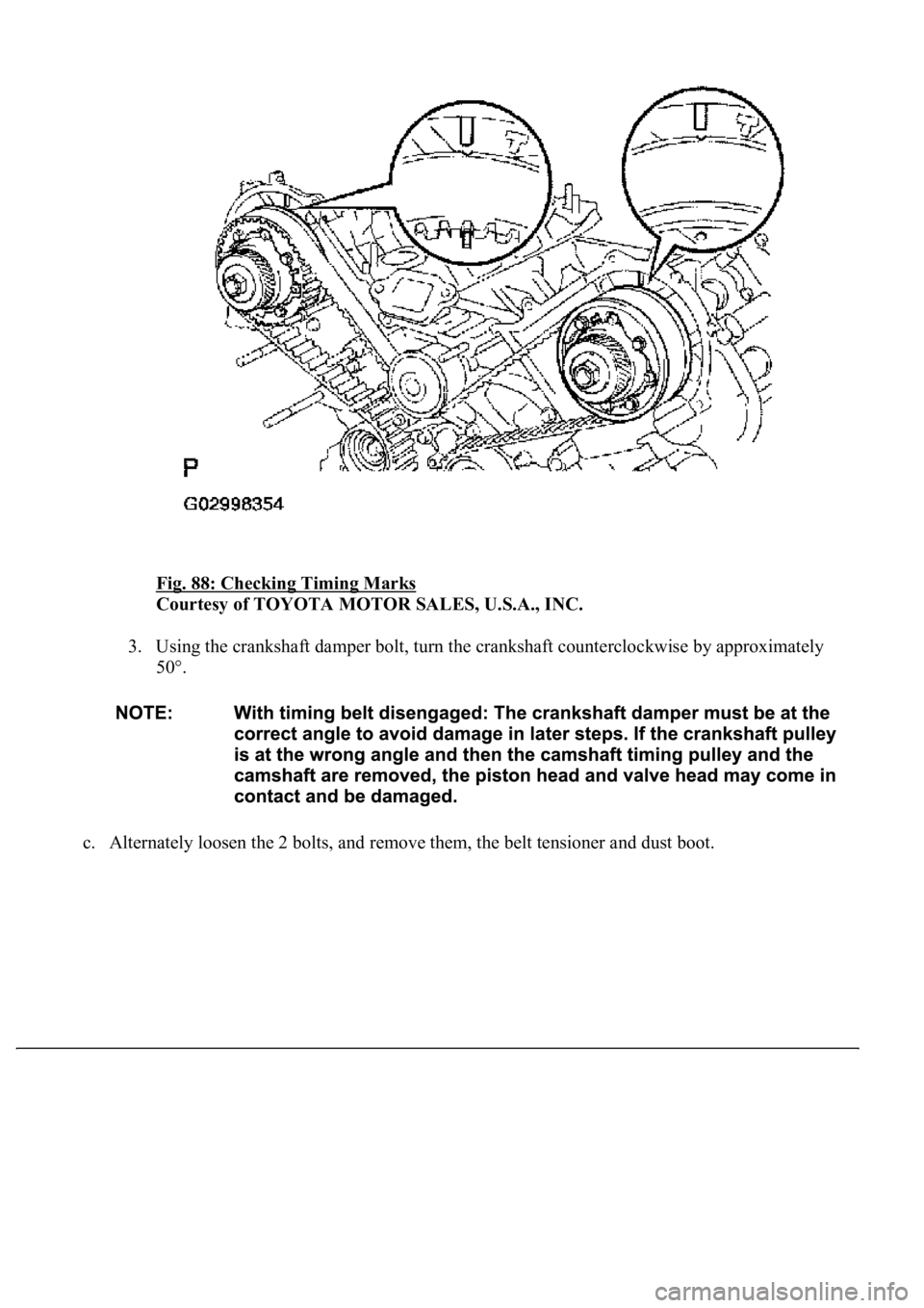
Fig. 88: Checking Timing Marks
Courtesy of TOYOTA MOTOR SALES, U.S.A., INC.
3. Using the crankshaft damper bolt, turn the crankshaft counterclockwise by approximately
50°.
c. Alternatel
y loosen the 2 bolts, and remove them, the belt tensioner and dust boot.
Page 3425 of 4500
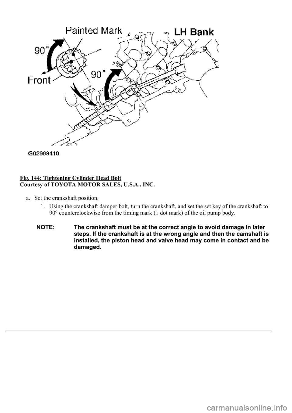
Fig. 144: Tightening Cylinder Head Bolt
Courtesy of TOYOTA MOTOR SALES, U.S.A., INC.
a. Set the crankshaft position.
1. Using the crankshaft damper bolt, turn the crankshaft, and set the set key of the crankshaft to
90° counterclockwise from the timing mark (1 dot mark) of the oil pump body.
Page 3451 of 4500
Fig. 170: Turning Camshaft Timing Pulleys
Courtesy of TOYOTA MOTOR SALES, U.S.A., INC.
2. Using the crankshaft damper bolt, turn the crankshaft to align the timing marks of the
crankshaft timin
g pulley and oil pump body.
Page 3454 of 4500
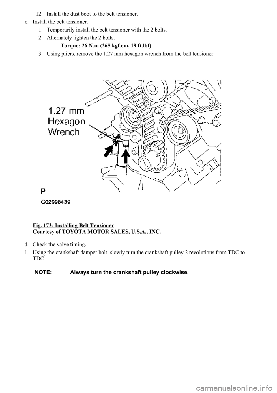
12. Install the dust boot to the belt tensioner.
c. Install the belt tensioner.
1. Temporarily install the belt tensioner with the 2 bolts.
2. Alternately tighten the 2 bolts.
Torque: 26 N.m (265 kgf.cm, 19 ft.lbf)
3. Using pliers, remove the 1.27 mm hexagon wrench from the belt tensioner.
Fig. 173: Installing Belt Tensioner
Courtesy of TOYOTA MOTOR SALES, U.S.A., INC.
d. Check the valve timing.
1. Using the crankshaft damper bolt, slowly turn the crankshaft pulley 2 revolutions from TDC to
TDC.