LEXUS LS430 2003 Factory Owner's Manual
LS430 2003
LEXUS
LEXUS
https://www.carmanualsonline.info/img/36/57050/w960_57050-0.png
LEXUS LS430 2003 Factory Owner's Manual
Page 339 of 4500
Fig. 107: Max Cool Damper Position Sensor Circuit (Passenger Side)
Courtesy of TOYOTA MOTOR SALES, U.S.A., INC.
INSPECTION PROCEDURE
1.READ VALUE ON HAND-HELD TESTER
a. Connect the hand-held tester to the DLC3.
b. Turn the ignition switch to the ON position and push the hand-held tester main switch on.
c. Select the item below in the DATA LIST, and read the display on the hand-held tester.
DATA LIST / AIR CONDITIONER:
DATA LIST / AIR CONDITIONER
ItemMeasure Item/Display (Range)Normal ConditionDiagnostic
Note
A/B DAMP
POS-PCool air bypass damper position (Passenger
side) / min.: -14% max.: 113.5%OPEN: Approx. 0 %
SHUT: Approx. 100%-
Page 342 of 4500
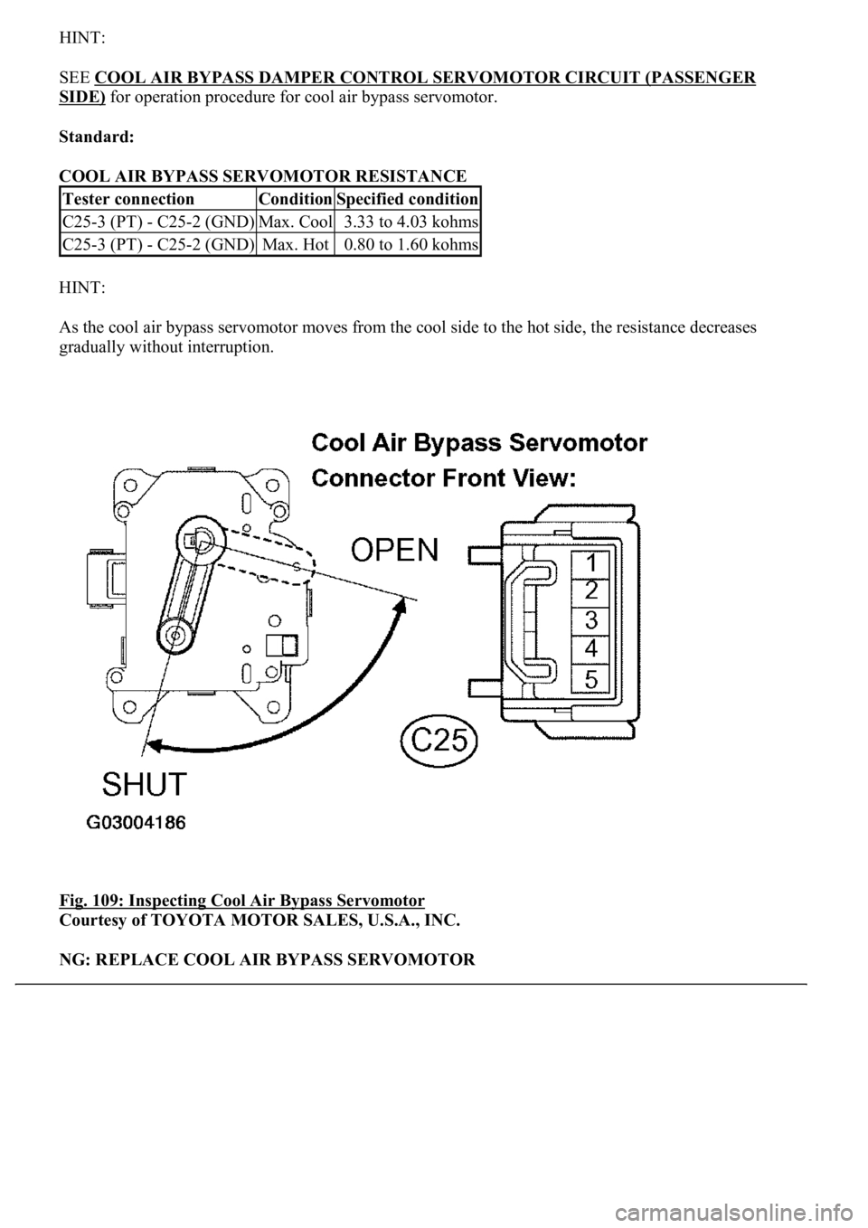
HINT:
SEE COOL AIR BYPASS DAMPER CONTROL SERVOMOTOR CIRCUIT (PASSENGER
SIDE) for operation procedure for cool air bypass servomotor.
Standard:
COOL AIR BYPASS SERVOMOTOR RESISTANCE
HINT:
As the cool air bypass servomotor moves from the cool side to the hot side, the resistance decreases
gradually without interruption.
Fig. 109: Inspecting Cool Air Bypass Servomotor
Courtesy of TOYOTA MOTOR SALES, U.S.A., INC.
NG: REPLACE COOL AIR BYPASS SERVOMOTOR
Tester connectionConditionSpecified condition
C25-3 (PT) - C25-2 (GND)Max. Cool3.33 to 4.03 kohms
C25-3 (PT) - C25-2 (GND)Max. Hot0.80 to 1.60 kohms
Page 346 of 4500
Fig. 112: Air Inlet Damper Control Servomotor Circuit
Courtesy of TOYOTA MOTOR SALES, U.S.A., INC.
INSPECTION PROCEDURE
1.PERFORM ACTUATOR CHECK
a. Remove the glove box to see and check the air inlet servomotor operation.
b. Set the actuator check mode (SEE ACTUATOR CHECK
).
c. Press the DEF switch to set the STEP operation.
d. Press the DEF switch in order and check the operation of the air inlet servomotor.
Page 347 of 4500
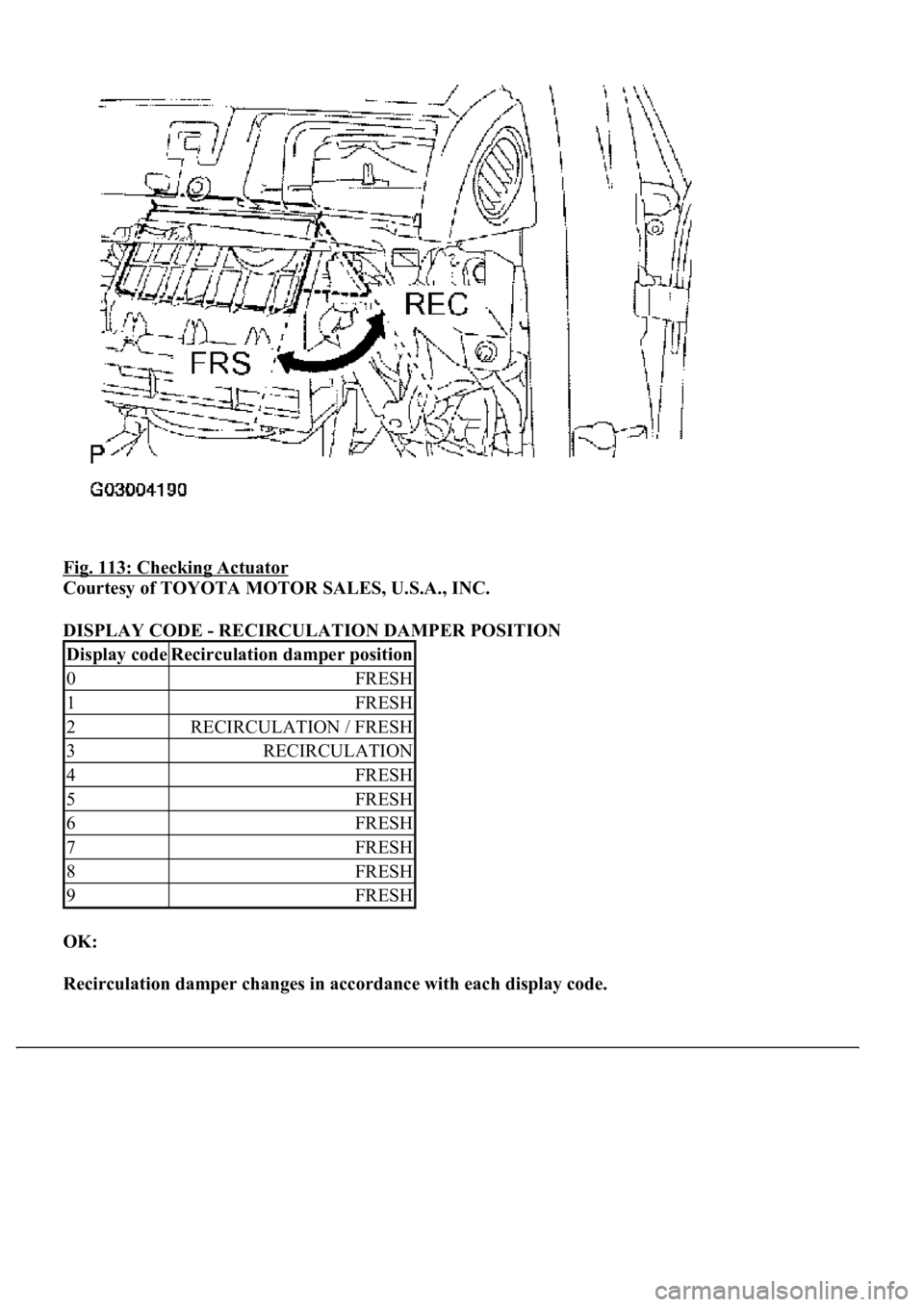
Fig. 113: Checking Actuator
Courtesy of TOYOTA MOTOR SALES, U.S.A., INC.
DISPLAY CODE - RECIRCULATION DAMPER POSITION
OK:
Recirculation damper changes in accordance with each display code.
Display codeRecirculation damper position
0FRESH
1FRESH
2RECIRCULATION / FRESH
3RECIRCULATION
4FRESH
5FRESH
6FRESH
7FRESH
8FRESH
9FRESH
Page 363 of 4500
NG: REPAIR OR REPLACE HARNESS OR CONNECTOR
OK: REPLACE AIR CONDITIONING AMPLIFIER (SEE REPLACEMENT )
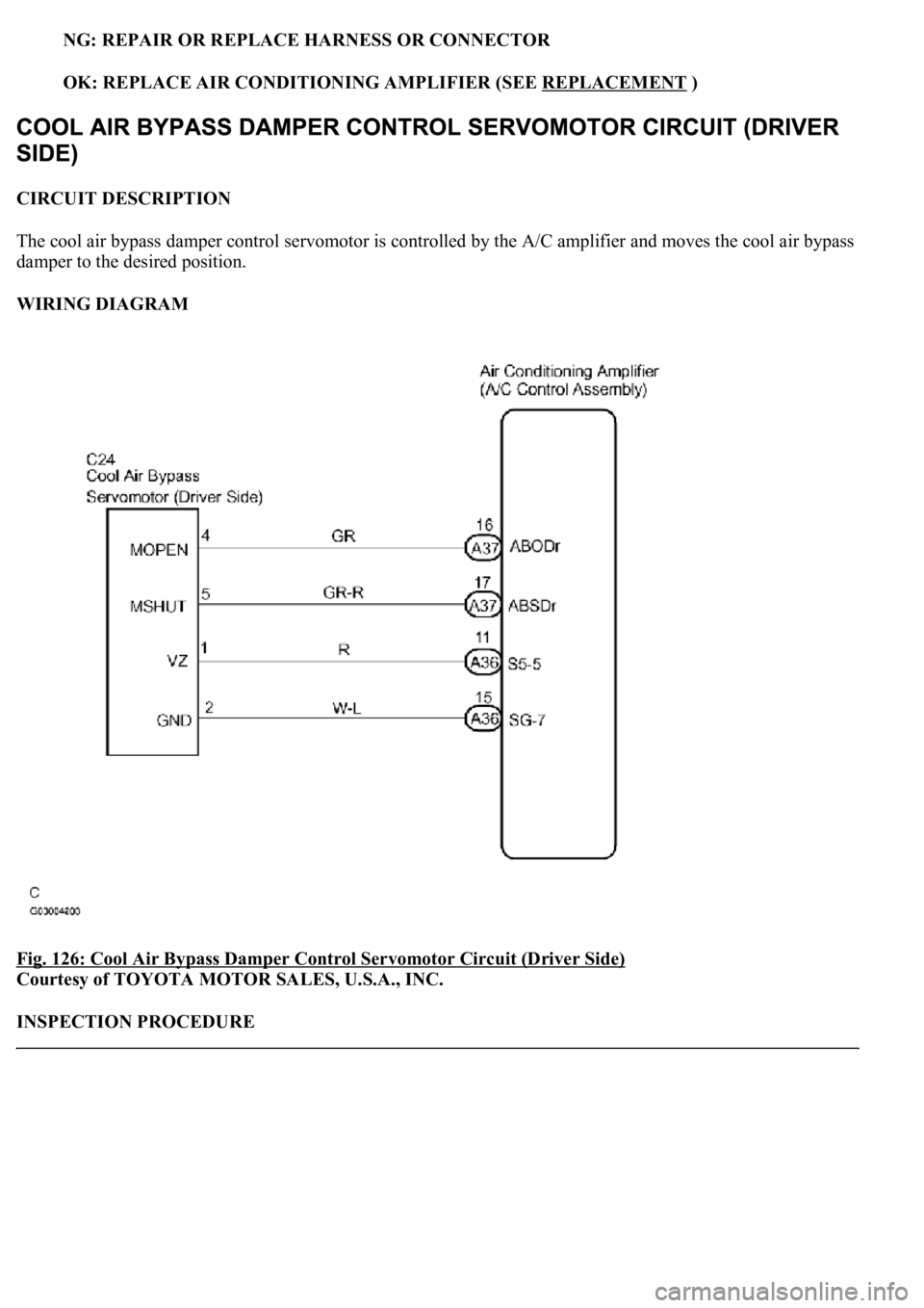
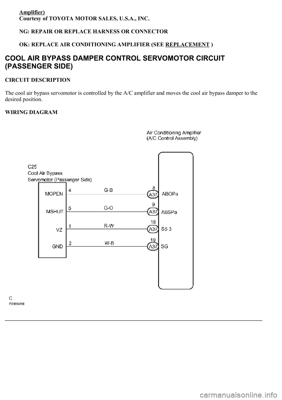
CIRCUIT DESCRIPTION
The cool air bypass damper control servomotor is controlled by the A/C amplifier and moves the cool air bypass
damper to the desired position.
WIRING DIAGRAM
Fig. 126: Cool Air Bypass Damper Control Servomotor Circuit (Driver Side)
Courtesy of TOYOTA MOTOR SALES, U.S.A., INC.
INSPECTION PROCEDURE
Page 364 of 4500
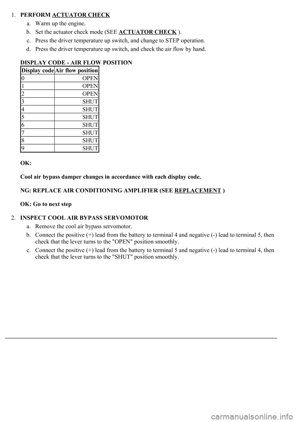
1.PERFORM ACTUATOR CHECK
a. Warm up the engine.
b. Set the actuator check mode (SEE ACTUATOR CHECK
).
c. Press the driver temperature up switch, and change to STEP operation.
d. Press the driver temperature up switch, and check the air flow by hand.
DISPLAY CODE - AIR FLOW POSITION
OK:
Cool air bypass damper changes in accordance with each display code.
NG: REPLACE AIR CONDITIONING AMPLIFIER (SEE REPLACEMENT
)
OK: Go to next step
2.INSPECT COOL AIR BYPASS SERVOMOTOR
a. Remove the cool air bypass servomotor.
b. Connect the positive (+) lead from the battery to terminal 4 and negative (-) lead to terminal 5, then
check that the lever turns to the "OPEN" position smoothly.
c. Connect the positive (+) lead from the battery to terminal 5 and negative (-) lead to terminal 4, then
check that the lever turns to the "SHUT" position smoothl
y.
Display codeAir flow position
0OPEN
1OPEN
2OPEN
3SHUT
4SHUT
5SHUT
6SHUT
7SHUT
8SHUT
9SHUT
Page 368 of 4500
Amplifier)
Courtesy of TOYOTA MOTOR SALES, U.S.A., INC.
NG: REPAIR OR REPLACE HARNESS OR CONNECTOR
OK: REPLACE AIR CONDITIONING AMPLIFIER (SEE REPLACEMENT
)
CIRCUIT DESCRIPTION
The cool air bypass servomotor is controlled by the A/C amplifier and moves the cool air bypass damper to the
desired position.
WIRING DIAGRAM
Page 369 of 4500

Fig. 129: Cool Air Bypass Damper Control Servomotor Circuit (Passenger Side)
Courtesy of TOYOTA MOTOR SALES, U.S.A., INC.
INSPECTION PROCEDURE
1.PERFORM ACTUATOR CHECK
a. Warm up the engine.
b. Set the actuator check mode (SEE ACTUATOR CHECK
).
c. Press the driver temperature up switch, and change to STEP operation.
d. Press the driver temperature up switch, and check the air flow by hand.
Display code Air flow position
DISPLAY CODE AIR FLOW POSITION
OK:
Cool air bypass damper changes in accordance with each display code.
NG: REPLACE AIR CONDITIONING AMPLIFIER (SEE REPLACEMENT
)
OK: Go to next step
2.INSPECT COOL AIR BYPASS SERVOMOTOR
a. Remove the cool air bypass servomotor.
b. Connect the positive (+) lead from the battery to terminal 4 and negative (-) lead to terminal 5, then
check that the lever turns to the "OPEN" position smoothly.
c. Connect the positive (+) lead from the battery to terminal 5 and negative (-) lead to terminal 4, then
check that the lever turns to the "SHUT" position smoothly.
Display codeAir flow lever position
0OPEN
1OPEN
2OPEN
3SHUT
4SHUT
5SHUT
6SHUT
7SHUT
8SHUT
9SHUT
Page 378 of 4500
Amplifier)
Courtesy of TOYOTA MOTOR SALES, U.S.A., INC.
NG: REPAIR OR REPLACE HARNESS OR CONNECTOR
OK: REPLACE AIR CONDITIONING AMPLIFIER (SEE REPLACEMENT
)
CIRCUIT DESCRIPTION
This circuit turns the servomotor and changes each damper position by receiving the signals from the A/C
amplifier assy. When the AUTO switch is on, the A/C amplifier changes the mode between "FACE", "BI-
LEVEL" and "FOOT" following the temperature setting.
WIRING DIAGRAM
Page 379 of 4500
Fig. 136: Air Vent Mode Damper Control Servomotor Circuit
Courtesy of TOYOTA MOTOR SALES, U.S.A., INC.
INSPECTION PROCEDURE
1.PERFORM ACTUATOR CHECK
a. Warm up the engine.
b. Set the actuator check mode (see ACTUATOR CHECK).