damper LEXUS LS430 2003 Factory Owner's Guide
[x] Cancel search | Manufacturer: LEXUS, Model Year: 2003, Model line: LS430, Model: LEXUS LS430 2003Pages: 4500, PDF Size: 87.45 MB
Page 388 of 4500
Courtesy of TOYOTA MOTOR SALES, U.S.A., INC.
OK: REPLACE AIR CONDITIONING AMPLIFIER (SEE REPLACEMENT
)
CIRCUIT DESCRIPTION
This servomotor is controlled by the A/C amplifier. Air flow temperature changes when moving the air mix
damper to the target point. The target point can be detected with the air mix damper position sensor.
WIRING DIAGRAM
Page 389 of 4500
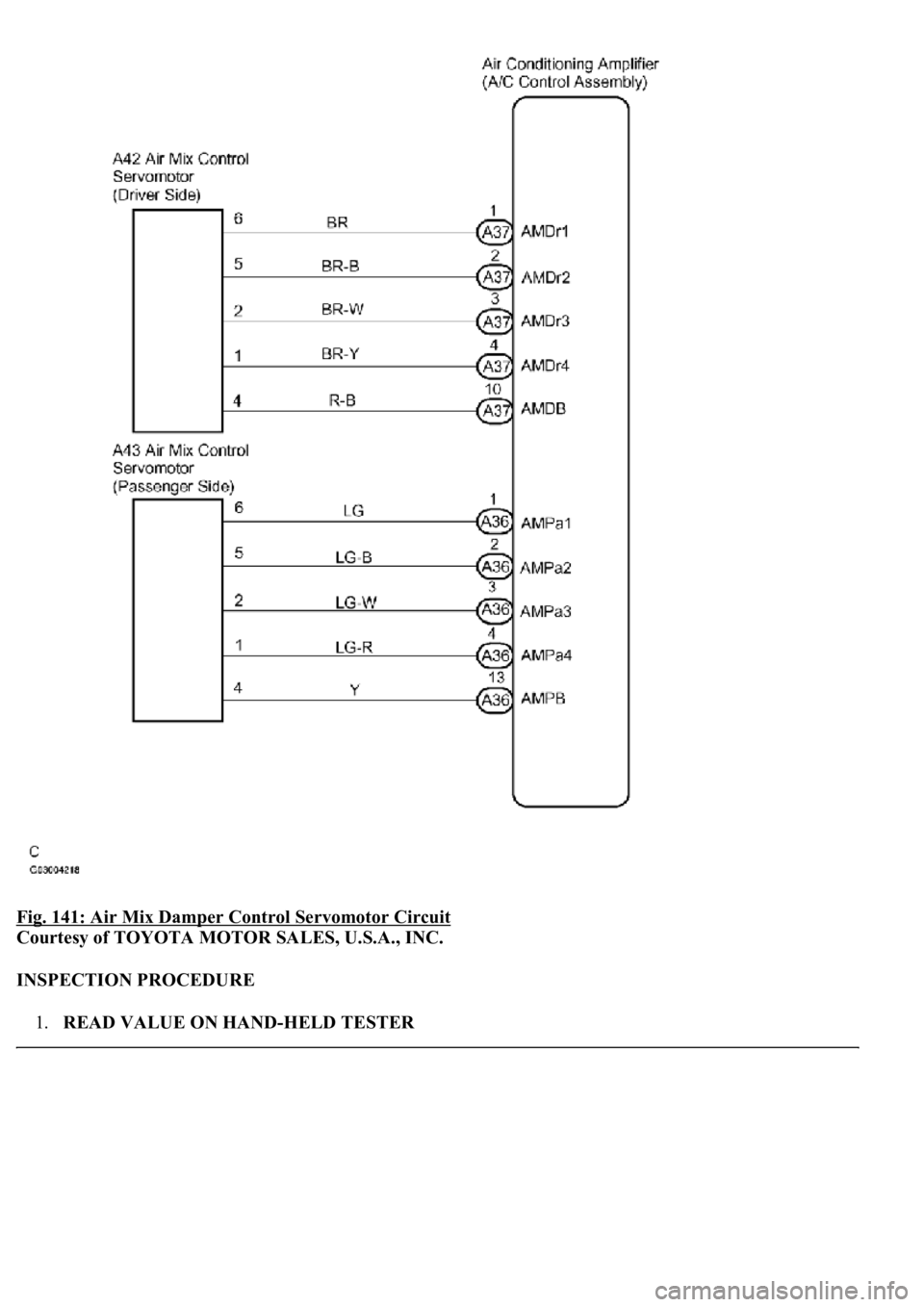
Fig. 141: Air Mix Damper Control Servomotor Circuit
Courtesy of TOYOTA MOTOR SALES, U.S.A., INC.
INSPECTION PROCEDURE
1.READ VALUE ON HAND-HELD TESTER
Page 390 of 4500
a. Connect the hand-held tester to the DLC3.
b. Turn the ignition switch to the ON position and push the hand-held tester main switch on.
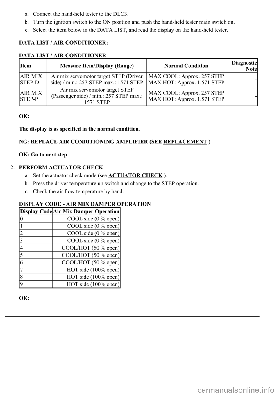
c. Select the item below in the DATA LIST, and read the display on the hand-held tester.
DATA LIST / AIR CONDITIONER:
DATA LIST / AIR CONDITIONER
OK:
The display is as specified in the normal condition.
NG: REPLACE AIR CONDITIONING AMPLIFIER (SEE REPLACEMENT
)
OK: Go to next step
2.PERFORM ACTUATOR CHECK
a. Set the actuator check mode (see ACTUATOR CHECK
).
b. Press the driver temperature up switch and change to the STEP operation.
c. Check the air flow temperature by hand.
DISPLAY CODE - AIR MIX DAMPER OPERATION
OK:
ItemMeasure Item/Display (Range)Normal ConditionDiagnostic
Note
AIR MIX
STEP-DAir mix servomotor target STEP (Driver
side) / min.: 257 STEP max.: 1571 STEPMAX COOL: Approx. 257 STEP
MAX HOT: Approx. 1,571 STEP-
AIR MIX
STEP-PAir mix servomotor target STEP
(Passenger side) / min.: 257 STEP max.:
1571 STEPMAX COOL: Approx. 257 STEP
MAX HOT: Approx. 1,571 STEP-
Display CodeAir Mix Damper Operation
0COOL side (0 % open)
1COOL side (0 % open)
2COOL side (0 % open)
3COOL side (0 % open)
4COOL/HOT (50 % open)
5COOL/HOT (50 % open)
6COOL/HOT (50 % open)
7HOT side (100% open)
8HOT side (100% open)
9HOT side (100% open)
Page 443 of 4500
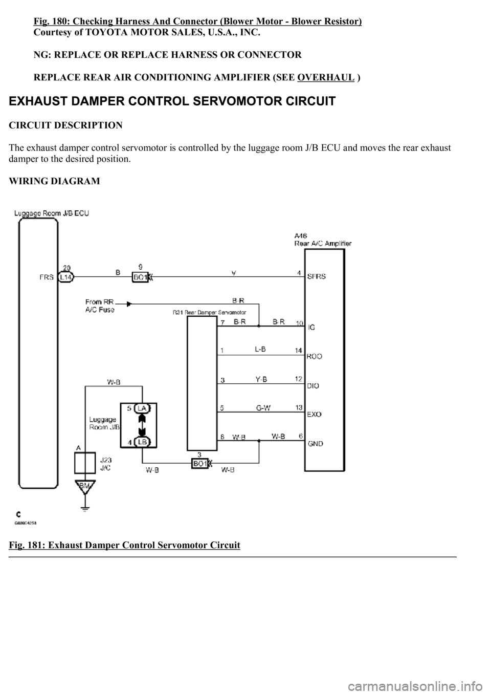
Fig. 180: Checking Harness And Connector (Blower Motor -Blower Resistor)
Courtesy of TOYOTA MOTOR SALES, U.S.A., INC.
NG: REPLACE OR REPLACE HARNESS OR CONNECTOR
REPLACE REAR AIR CONDITIONING AMPLIFIER (SEE OVERHAUL
)
CIRCUIT DESCRIPTION
The exhaust damper control servomotor is controlled by the luggage room J/B ECU and moves the rear exhaust
damper to the desired position.
WIRING DIAGRAM
Fig. 181: Exhaust Damper Control Servomotor Circuit
Page 444 of 4500
Courtesy of TOYOTA MOTOR SALES, U.S.A., INC.
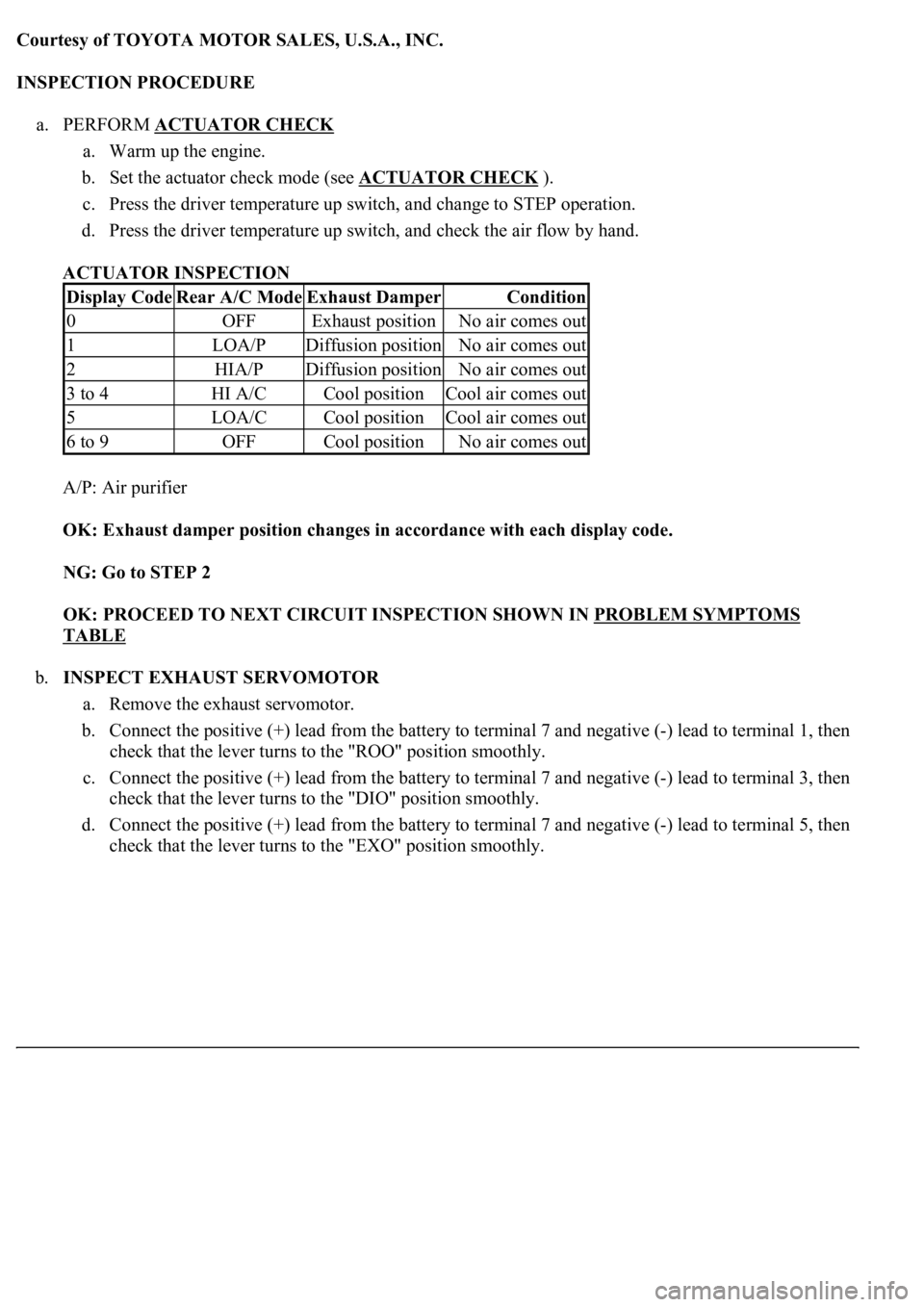
INSPECTION PROCEDURE
a. PERFORM ACTUATOR CHECK
a. Warm up the engine.
b. Set the actuator check mode (see ACTUATOR CHECK
).
c. Press the driver temperature up switch, and change to STEP operation.
d. Press the driver temperature up switch, and check the air flow by hand.
ACTUATOR INSPECTION
A/P: Air purifier
OK: Exhaust damper position changes in accordance with each display code.
NG: Go to STEP 2
OK: PROCEED TO NEXT CIRCUIT INSPECTION SHOWN IN PROBLEM SYMPTOMS
TABLE
b.INSPECT EXHAUST SERVOMOTOR
a. Remove the exhaust servomotor.
b. Connect the positive (+) lead from the battery to terminal 7 and negative (-) lead to terminal 1, then
check that the lever turns to the "ROO" position smoothly.
c. Connect the positive (+) lead from the battery to terminal 7 and negative (-) lead to terminal 3, then
check that the lever turns to the "DIO" position smoothly.
d. Connect the positive (+) lead from the battery to terminal 7 and negative (-) lead to terminal 5, then
check that the lever turns to the "EXO" position smoothl
y.
Display CodeRear A/C ModeExhaust DamperCondition
0OFFExhaust positionNo air comes out
1LOA/PDiffusion positionNo air comes out
2HIA/PDiffusion positionNo air comes out
3 to 4HI A/CCool positionCool air comes out
5LOA/CCool positionCool air comes out
6 to 9OFFCool positionNo air comes out
Page 492 of 4500
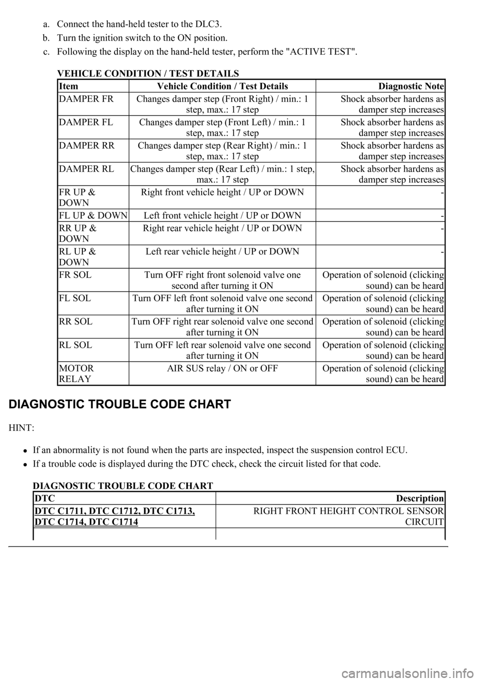
a. Connect the hand-held tester to the DLC3.
b. Turn the ignition switch to the ON position.
c. Following the display on the hand-held tester, perform the "ACTIVE TEST".
VEHICLE CONDITION / TEST DETAILS
HINT:
If an abnormality is not found when the parts are inspected, inspect the suspension control ECU.
If a trouble code is displayed during the DTC check, check the circuit listed for that code.
DIAGNOSTIC TROUBLE CODE CHART
ItemVehicle Condition / Test DetailsDiagnostic Note
DAMPER FRChanges damper step (Front Right) / min.: 1
step, max.: 17 stepShock absorber hardens as
damper step increases
DAMPER FLChanges damper step (Front Left) / min.: 1
step, max.: 17 stepShock absorber hardens as
damper step increases
DAMPER RRChanges damper step (Rear Right) / min.: 1
step, max.: 17 stepShock absorber hardens as
damper step increases
DAMPER RLChanges damper step (Rear Left) / min.: 1 step,
max.: 17 stepShock absorber hardens as
damper step increases
FR UP &
DOWNRight front vehicle height / UP or DOWN-
FL UP & DOWNLeft front vehicle height / UP or DOWN-
RR UP &
DOWNRight rear vehicle height / UP or DOWN-
RL UP &
DOWNLeft rear vehicle height / UP or DOWN-
FR SOLTurn OFF right front solenoid valve one
second after turning it ONOperation of solenoid (clicking
sound) can be heard
FL SOLTurn OFF left front solenoid valve one second
after turning it ONOperation of solenoid (clicking
sound) can be heard
RR SOLTurn OFF right rear solenoid valve one second
after turning it ONOperation of solenoid (clicking
sound) can be heard
RL SOLTurn OFF left rear solenoid valve one second
after turning it ONOperation of solenoid (clicking
sound) can be heard
MOTOR
RELAYAIR SUS relay / ON or OFFOperation of solenoid (clicking
sound) can be heard
DTCDescription
DTC C1711, DTC C1712, DTC C1713,
DTC C1714, DTC C1714
RIGHT FRONT HEIGHT CONTROL SENSOR
CIRCUIT
Page 536 of 4500

b. Turn the ignition switch to the ON position and turn the hand-held tester main switch on.
c. Select the item below in the ACTIVE TEST and operate it with the hand-held tester.
NORMAL CONDITION DESCRIPTION
d. Check the hardness of the absorber while operating the absorber control actuator level from 1 to 17
or from 17 to 1 through the ACTIVE TEST.
OK:
Hardness of the absorber becomes harder or softer.
NG: Go to step 2
OK: REPLACE SUSPENSION CONTROL ECU (SEE REPLACEMENT
)
2.INSPECT ABSORBER CONTROL ACTUATOR
a. Disconnect the absorber control actuator connector.
b. Measure the resistance according to the value (s) in the table below.
TESTER CONNECTION STANDARD SPECIFIED CONDITION STANDARD (FRONT RH)
ItemNormal Condition
DAMPER FR1 to 17 step (The absorber becomes softer as the level approaches to 1 and harder
as the level approaches to 17)
DAMPER FL1 to 17 step (The absorber becomes softer as the level approaches to 1 and harder
as the level approaches to 17)
DAMPER RR1 to 17 step (The absorber becomes softer as the level approaches to 1 and harder
as the level approaches to 17)
DAMPER RL1 to 17 step (The absorber becomes softer as the level approaches to 1 and harder
as the level approaches to 17)
Tester ConnectionSpecified Condition
1 (FBR+) - 3 (GND)12.0 to 12.8 ohms
2 (FAR+) - 3 (GND)12.0 to 12.8 ohms
3 (GND) - 4 (FBR-)12.0 to 12.8 ohms
3 (GND) - 5 (FAR-)12.0 to 12.8 ohms
Page 1986 of 4500
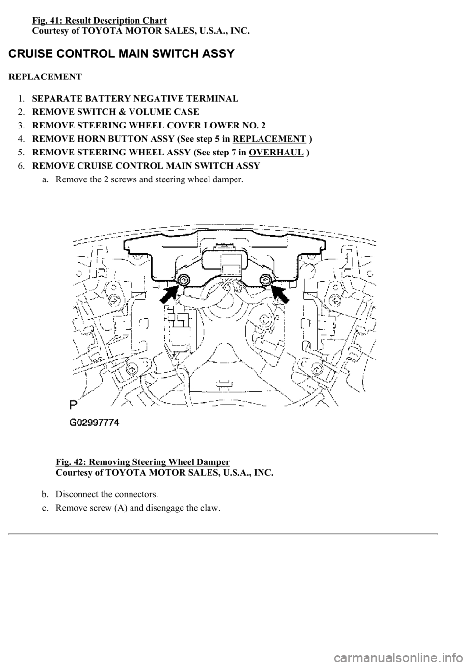
Fig. 41: Result Description Chart
Courtesy of TOYOTA MOTOR SALES, U.S.A., INC.
REPLACEMENT
1.SEPARATE BATTERY NEGATIVE TERMINAL
2.REMOVE SWITCH & VOLUME CASE
3.REMOVE STEERING WHEEL COVER LOWER NO. 2
4.REMOVE HORN BUTTON ASSY (See step 5 in REPLACEMENT
)
5.REMOVE STEERING WHEEL ASSY (See step 7 in OVERHAUL
)
6.REMOVE CRUISE CONTROL MAIN SWITCH ASSY
a. Remove the 2 screws and steering wheel damper.
Fig. 42: Removing Steering Wheel Damper
Courtesy of TOYOTA MOTOR SALES, U.S.A., INC.
b. Disconnect the connectors.
c. Remove screw (A) and disengage the claw.
Page 2421 of 4500

HVAC DIAGNOSTIC TROUBLE CODE (DTC) IDENTIFICATION
LIGHTING SYSTEM DIAGNOSTIC TROUBLE CODE (DTC) IDENTIFICATION
SENSOR/SWITCH "D"/"E" VOLTAGE
CORRELATION
DTC P2121 THROTTLE/PEDAL POSITION
SENSOR/SWITCH "D" CIRCUIT
RANGE/PERFORMANCE
DTC U0001 HIGH SPEED CAN COMMUNICATION
CIRCUIT
DTCDescription
DTC B1411 ROOM TEMPERATURE SENSOR CIRCUIT
DTC B1412 AMBIENT TEMPERATURE SENSOR CIRCUIT
DTC B1413 EVAPORATOR TEMPERATURE SENSOR CIRCUIT
DTC B1415 AIR DUCT SENSOR CIRCUIT (DRIVER SIDE)
DTC B1416 AIR DUCT SENSOR CIRCUIT (PASSENGER SIDE)
DTC B1418 EMISSION GAS SENSOR CIRCUIT
DTC B1421 SOLAR SENSOR CIRCUIT (PASSENGER SIDE)
DTC B1423 PRESSURE SWITCH CIRCUIT
DTC B1424 SOLAR SENSOR CIRCUIT (DRIVER SIDE)
DTC B1428 REAR SOLAR SENSOR CIRCUIT
DTC B1432 AIR INLET DAMPER POSITION SENSOR CIRCUIT
DTC B1434 MAX COOL DAMPER POSITION SENSOR CIRCUIT (DRIVER SIDE)
DTC B1435 MAX COOL DAMPER POSITION SENSOR CIRCUIT (PASSENGER SIDE)
DTC B1442 AIR INLET DAMPER CONTROL SERVOMOTOR CIRCUIT
DTC B1451 COMPRESSOR SOLENOID CIRCUIT
DTC B1461 EMISSION GAS NOX SENSOR CIRCUIT
DTCDescription
DTC B1244 LIGHT SENSOR CIRCUIT MALFUNCTION
DTC B1268 BACK-UP COMMUNICATION BUS MALFUNCTION
DTC B2402, B2403 TRANSISTOR RELAY OVERLOAD/OVERHEAT MALFUNCTION
DTC B2412, B2413 HEADLIGHT SWIVEL MOTOR LH/RH MALFUNCTION
DTC B2414 STEERING POSITION SENSOR MALFUNCTION
DTC B2415 VEHICLE SPEED SENSOR MALFUNCTION
DTC B2416 HEIGHT CONTROL SENSOR MALFUNCTION
DTC B2417, B2418 HEADLIGHT BEAM LEVEL CONTROL MOTOR LH/RH
MALFUNCTION
Page 2630 of 4500

Fuel Lid Opener MotorOn left side of luggage compartment, behind left
rear fenderwell. See Fig. 19
.
Headlight Beam Level Control Actuator LHBehind left headlight. See Fig. 13 .
Headlight Beam Level Control Actuator RHBehind right headlight. See Fig. 13 .
Headlight Cleaner MotorBelow left headlight. See Fig. 13 .
Height Control CompressorOn right front of engine compartment. See Fig. 13 .
Luggage Compartment Door Closer MotorOn center rear of luggage compartment lid. See Fig.
28 .
Power Seat Module (Rear Passenger's RH Seat Slide
Control)Right side of rear seat. See Fig. 32 .
Power Seat Motor (Driver's Seat Cushion Control)Lower left side of driver's seat. See Fig. 31 .
Power Seat Motor (Driver's Seat Front Vertical
Control)Lower left side of driver's seat. See Fig. 31 .
Power Seat Motor (Driver's Seat Lifter Control)Lower right side of driver's seat bottom. See Fig.
31 .
Power Seat Motor (Driver's Seat Lumbar Support
Lower Side Control)Lower right side of driver's seat cushion. See Fig.
31 .
Power Seat Motor (Driver's Seat Lumbar Support
Upper Side Control)Upper right side of driver's seat back. See Fig. 31 .
Power Seat Motor (Driver's Seat Reclining Control)Lower left rear side of driver's seat bottom. See Fig.
31 .
Power Seat Motor (Driver's Seat Slide Control)In lower left side of driver's seat cushion. See Fig.
31 .
Power Seat Motor (Front Passenger's Seat Front
Vertical Control)In lower right side of front passenger's seat bottom.
See Fig. 31
.
Power Seat Motor (Front Passenger's Seat Head
Rest Control)In upper left side of front passenger's seat back. See
Fig. 31
.
Power Seat Motor (Front Passenger's Seat Lifter
Control)In lower left side of front passenger's seat bottom.
See Fig. 31
.
Power Seat Motor (Front Passenger's Seat Lumbar
Support Control)Lower left rear of front passenger seat cushion. See
Fig. 31
.
Power Seat Motor (Front Passenger's Seat Reclining
Control)Lower right side of front passenger's seat. See Fig.
31 .
Power Seat Motor (Front Passenger's Seat Slide
Control)Under passenger's seat cushion. See Fig. 31 .
Power Seat Motor (Rear Passenger's LH Seat Slide
Control)Left side of rear seat. See Fig. 32 .
Power Window Motor Front LHIn left front door. See Fig. 29 .
Power Window Motor Front RHIn right front door. See Fig. 29 .
Power Window Motor Rear LHIn left rear door. See Fig. 29 .
Power Window Motor Rear RHIn right rear door. See Fig. 29 .
Rear Blower MotorCenter rear of vehicle. See Fig. 29 .
Rear Damper Servo MotorRear center of luggage compartment. See Fig. 29 .