LEXUS LS430 2003 Factory Manual PDF
LS430 2003
LEXUS
LEXUS
https://www.carmanualsonline.info/img/36/57050/w960_57050-0.png
LEXUS LS430 2003 Factory Manual PDF
Page 3392 of 4500
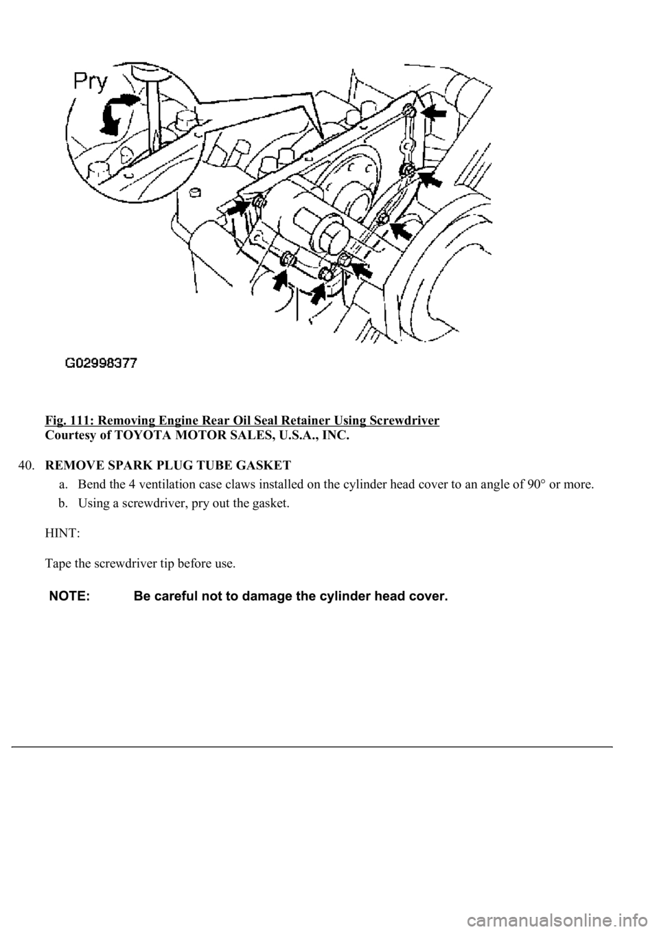
Fig. 111: Removing Engine Rear Oil Seal Retainer Using Screwdriver
Courtesy of TOYOTA MOTOR SALES, U.S.A., INC.
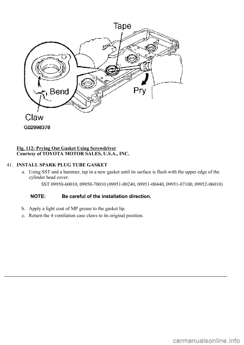
40.REMOVE SPARK PLUG TUBE GASKET
a. Bend the 4 ventilation case claws installed on the cylinder head cover to an angle of 90° or more.
b. Using a screwdriver, pry out the gasket.
HINT:
Tape the screwdriver tip before use.
Page 3393 of 4500
Fig. 112: Prying Out Gasket Using Screwdriver
Courtesy of TOYOTA MOTOR SALES, U.S.A., INC.
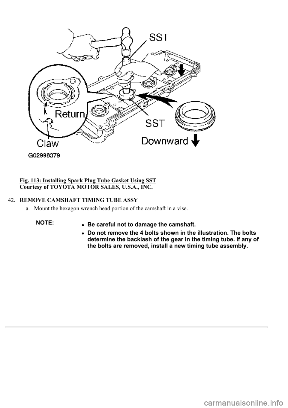
41.INSTALL SPARK PLUG TUBE GASKET
a. Using SST and a hammer, tap in a new gasket until its surface is flush with the upper edge of the
cylinder head cover.
SST 09950-60010, 09950-70010 (09951-00240, 09951-00440, 09951-07100, 09952-06010)
b. Apply a light coat of MP grease to the gasket lip.
c. Return the 4 ventilation case claws to its ori
ginal position.
Page 3394 of 4500
Fig. 113: Installing Spark Plug Tube Gasket Using SST
Courtesy of TOYOTA MOTOR SALES, U.S.A., INC.
42.REMOVE CAMSHAFT TIMING TUBE ASSY
a. Mount the hexagon wrench head portion of the camshaft in a vise.
Page 3399 of 4500
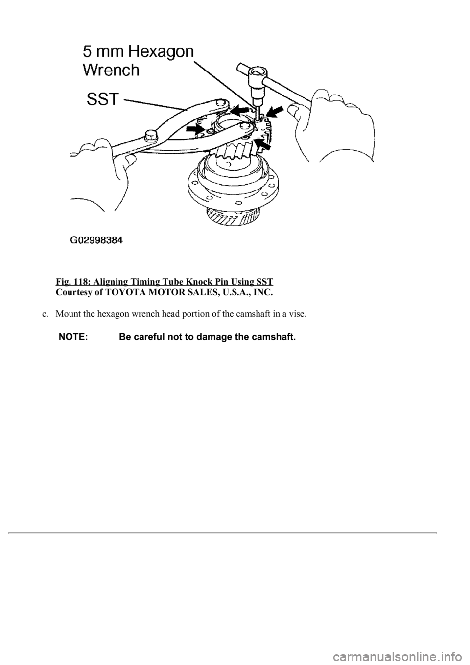
Fig. 118: Aligning Timing Tube Knock Pin Using SST
Courtesy of TOYOTA MOTOR SALES, U.S.A., INC.
c. Mount the hexagon wrench head portion of the camshaft in a vise.
Page 3400 of 4500
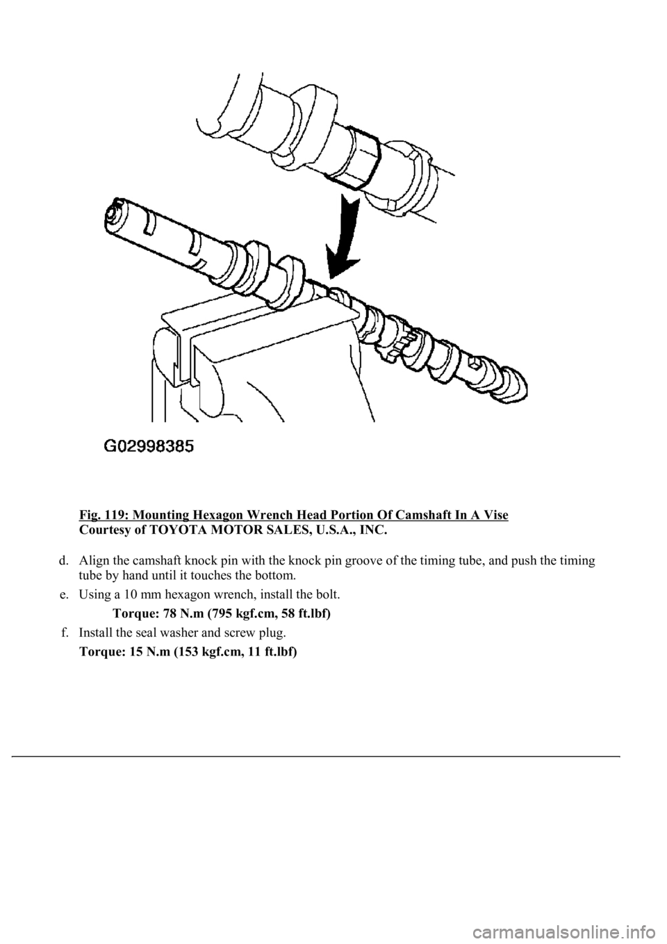
Fig. 119: Mounting Hexagon Wrench Head Portion Of Camshaft In A Vise
Courtesy of TOYOTA MOTOR SALES, U.S.A., INC.
d. Align the camshaft knock pin with the knock pin groove of the timing tube, and push the timing
tube by hand until it touches the bottom.
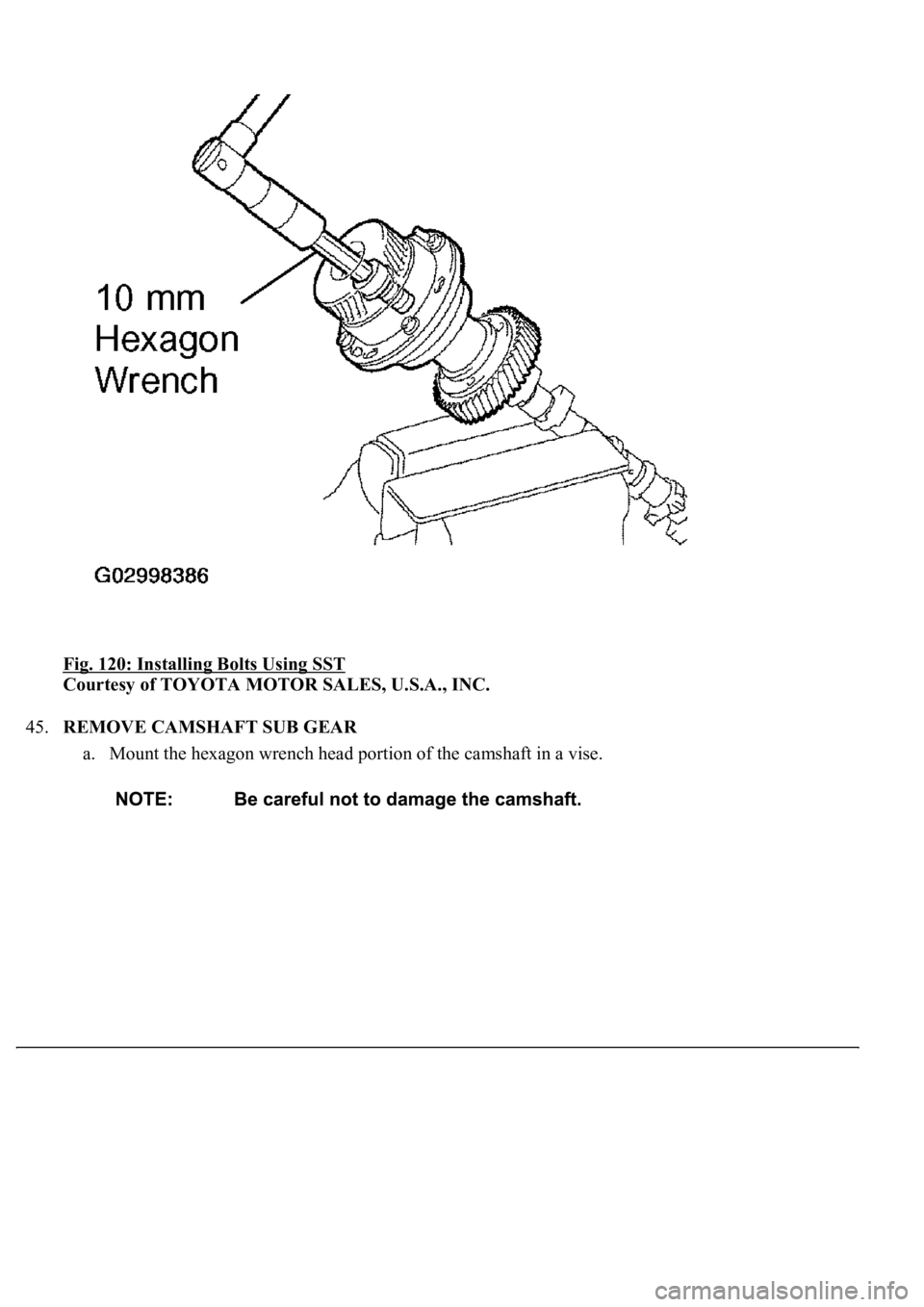
e. Using a 10 mm hexagon wrench, install the bolt.
Torque: 78 N.m (795 kgf.cm, 58 ft.lbf)
f. Install the seal washer and screw plug.
Torque: 15 N.m (153 kgf.cm, 11 ft.lbf)
Page 3401 of 4500
Fig. 120: Installing Bolts Using SST
Courtesy of TOYOTA MOTOR SALES, U.S.A., INC.
45.REMOVE CAMSHAFT SUB GEAR
a. Mount the hexagon wrench head portion of the camshaft in a vise.
Page 3402 of 4500
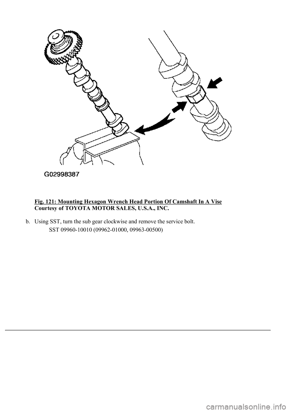
Fig. 121: Mounting Hexagon Wrench Head Portion Of Camshaft In A Vise
Courtesy of TOYOTA MOTOR SALES, U.S.A., INC.
b. Using SST, turn the sub gear clockwise and remove the service bolt.
SST 09960-10010 (09962-01000, 09963-00500)
Page 3407 of 4500
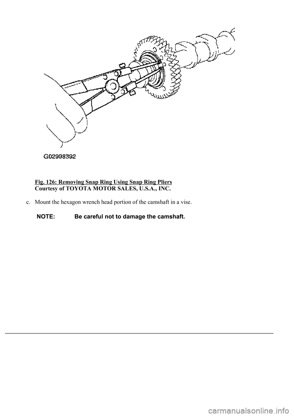
Fig. 126: Removing Snap Ring Using Snap Ring Pliers
Courtesy of TOYOTA MOTOR SALES, U.S.A., INC.
c. Mount the hexagon wrench head portion of the camshaft in a vise.
Page 3408 of 4500
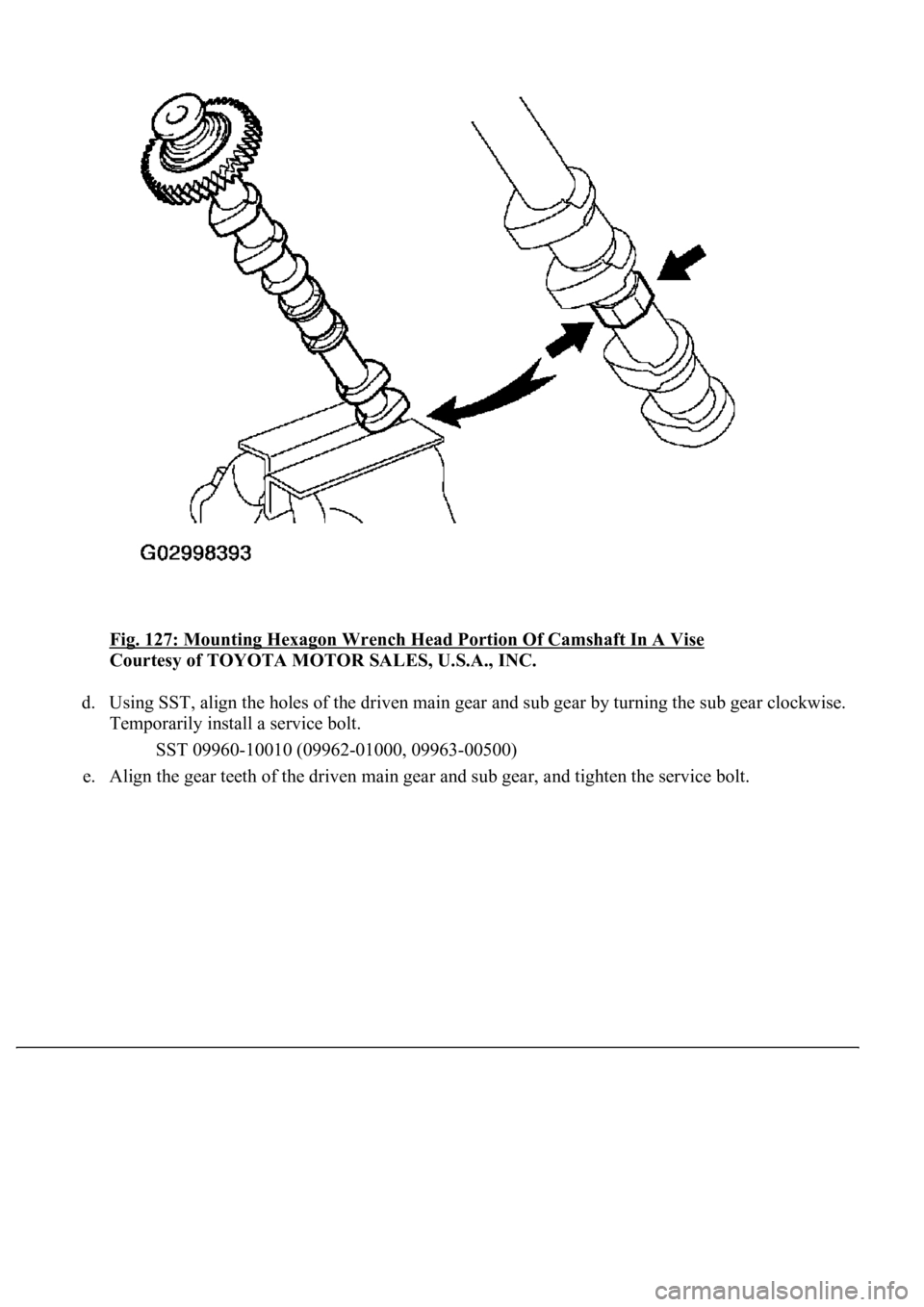
Fig. 127: Mounting Hexagon Wrench Head Portion Of Camshaft In A Vise
Courtesy of TOYOTA MOTOR SALES, U.S.A., INC.
d. Using SST, align the holes of the driven main gear and sub gear by turning the sub gear clockwise.
Temporarily install a service bolt.
SST 09960-10010 (09962-01000, 09963-00500)
e. Ali
gn the gear teeth of the driven main gear and sub gear, and tighten the service bolt.
Page 3417 of 4500
Fig. 136: Identifying Water Pump Assy Bolts
Courtesy of TOYOTA MOTOR SALES, U.S.A., INC.
60.INSTALL CYLINDER HEAD SUB-ASSY
a. Place a new cylinder head gasket on the cylinder block.
HINT:
The rear side of the cylinder head gasket has marks so that the RH and LH banks can be
distinguished. A "3R" mark is on the RH bank's gasket.
b. Place the cylinder head on the cylinder head gasket.