sensor LEXUS LS430 2003 Factory Repair Manual
[x] Cancel search | Manufacturer: LEXUS, Model Year: 2003, Model line: LS430, Model: LEXUS LS430 2003Pages: 4500, PDF Size: 87.45 MB
Page 2608 of 4500
Fig. 79: Disconnecting ECM E3 Connector
Courtesy of TOYOTA MOTOR SALES, U.S.A., INC.
NG: REPAIR OR REPLACE WIRE HARNESS OR CONNECTOR
OK: PROCEED TO NEXT CIRCUIT INSPECTION SHOWN IN PROBLEM SYMPTOMS
TABLE
3.CHECK WIRE HARNESS AND CONNECTOR (MILLIMETER WAVE RADAR SENSOR -
DISTANCE CONTROL ECU)
a. Disconnect the cruise control ECU (distance control ECU) connector.
b. Measure the resistance according to the value(s) in the table below.
Standard:
MILLIMETER WAVE RADAR SENSOR AND DISTANCE CONTROL ECU TERMINALS
RESISTANCE
Tester connectionConditionSpecified value
D2-13 (IGB) - M7-5 (IGB)AlwaysBelow 1 ohms
D2-13 (IGB) - Body groundAlways10 kohms or higher
Page 2609 of 4500
Fig. 80: Disconnecting Millimeter Wave Radar Sensor Connector
Courtesy of TOYOTA MOTOR SALES, U.S.A., INC.
Page 2620 of 4500

CIRCUIT DESCRIPTION
When the cruise control main switch is on, CRUISE main indicator light and READY indicator light come on.
This indicates the control condition (presence or absence of a vehicle in front, vehicle-to-vehicle distance, and
set vehicle speed) and fail-safe state through the multiplex communication system and CAN communication
system.
The master warning light and CRUISE main indicator light come on and vehicle-to-vehicle distance
information is displayed on the combination meter as the alarm buzzer sounds.
Items such as "Clean Radar Sensor", "Cruise not Available", "Check Cruise System" and "Radar Cruise Ready"
are displayed in the multi-information display on the combination meter when the ECM detects signals from
each sensor and actuator and sends them to the combination meter via CAN and BEAN.
HINT:
If the vehicle in front in the same lane significantly decreases vehicle speed or another vehicle pulls in front of
your vehicle, adequate deceleration cannot be applied and the vehicle-to-vehicle distance will shorten. At this
time, the system sounds the buzzer and the master warning light blinks to warn the driver.
Each indicator in the dynamic laser cruise control uses CAN and BEAN for communication. Therefore if there
are any malfunctions in this circuit, check for DTCs in the CAN communication and multiplex communication
systems.
INSPECTION PROCEDURE
1.PERFORM ACTIVE TEST BY HAND-HELD TESTER
a. Connect the hand-held tester to the DLC3.
b. Check the cruise control switch by using ACTIVE TEST.
COMBINATION METER:
ACTIVE TEST DETAIL (COMBINATION METER)
OK: Indicator light comes on.
NG: GO TO COMBINATION METER SYSTEM (SEE HOW TO PROCEED WITH
TROUBLESHOOTING )
DescriptionTester displayCheck condition
"CRUISE" indicator is ON / OFFCRUISE INDICON - OFF
Graphic area is ON / OFFL-CRUISE DISPON - OFF
"CHECK CRUISE SYSTEM" indicator is ON / OFFL-CRS CHECK INDON - OFF
"RADAR READY" indicator is ON / OFFL-CRS READY INDON - OFF
Page 2631 of 4500

SENDING UNITS & SENSORS LOCATION
Rear Door W/Motor Lock Assembly LHIn left rear door. See Fig. 29 .
Rear Door W/Motor Lock Assembly RHIn right rear door. See Fig. 29 .
Seat Belt Motor LHBase of left "B" pillar. See Fig. 30 .
Seat Belt Motor RHBase of right "B" pillar. See Fig. 30 .
Seat Climate Fan Motor Rear LH (Seat Back)In left rear seat back. See Fig. 32 .
Seat Climate Fan Motor Rear LH (Seat Cushion)In left rear seat cushion. See Fig. 32 .
Seat Climate Fan Motor Rear RH (Seat Back)In right rear seat back. See Fig. 32 .
Seat Climate Fan Motor Rear RH (Seat Cushion)In right rear seat cushion. See Fig. 32 .
Shoulder Belt Anchor Motor & Position Sensor
(Left)Near center of left "B" pillar. See Fig. 30 .
Shoulder Belt Anchor Motor (Right)Near center of right "B" pillar. See Fig. 30 .
StarterCenter rear of engine. See Fig. 15 .
Suspension Control Actuator Front LHOn left side of engine compartment. See Fig. 15 .
Suspension Control Actuator Front RHOn right side of engine compartment. See Fig. 15 .
Suspension Control Actuator Rear LHNear base of left "C" pillar. See Fig. 30 .
Suspension Control Actuator Rear RHNear base of right "C" pillar. See Fig. 30 .
Telescopic Motor & Position SensorInside base of steering column. See Fig. 18 .
Tilt Motor & Position SensorInside base of steering column. See Fig. 18 .
Washer MotorOn washer fluid reservoir, below left headlight. See
Fig. 15
.
Water Valve Servo MotorCenter of dash. See Fig. 18 .
ComponentLocation
ABS Speed Sensor Front LHAt left rear of engine compartment. See Fig. 12 .
ABS Speed Sensor & Pad Wear Indicator SW Front
RHRight rear of engine compartment. See Fig. 12 .
ABS Speed Sensor & Pad Wear Indicator SW Rear
RHAt right rear wheel assembly. See Fig. 19 .
ABS Speed Sensor Rear LHAt left rear wheel assembly. See Fig. 19 .
A/C Ambient Temp. SensorBehind left side of bumper fascia. See Fig. 12 .
Acceleration SensorOn left side of luggage compartment, behind left
rear fenderwell. See Fig. 19
.
Accel Position SensorBehind left center of dash. See Fig. 2 .
A/C Pressure SensorOn left front of engine compartment. See Fig. 12 .
A/C Room Temperature SensorBehind left center of dash. See Fig. 2 .
A/C Solar Sensor (Rear)Near center of rear speaker shelf, at base of rear
window. See Fig. 19
.
Airbag Sensor AssemblyFront of center console. See Fig. 2 .
Air Bag Sensor Front LHOn left front of engine compartment. See Fig. 12 .
Page 2632 of 4500
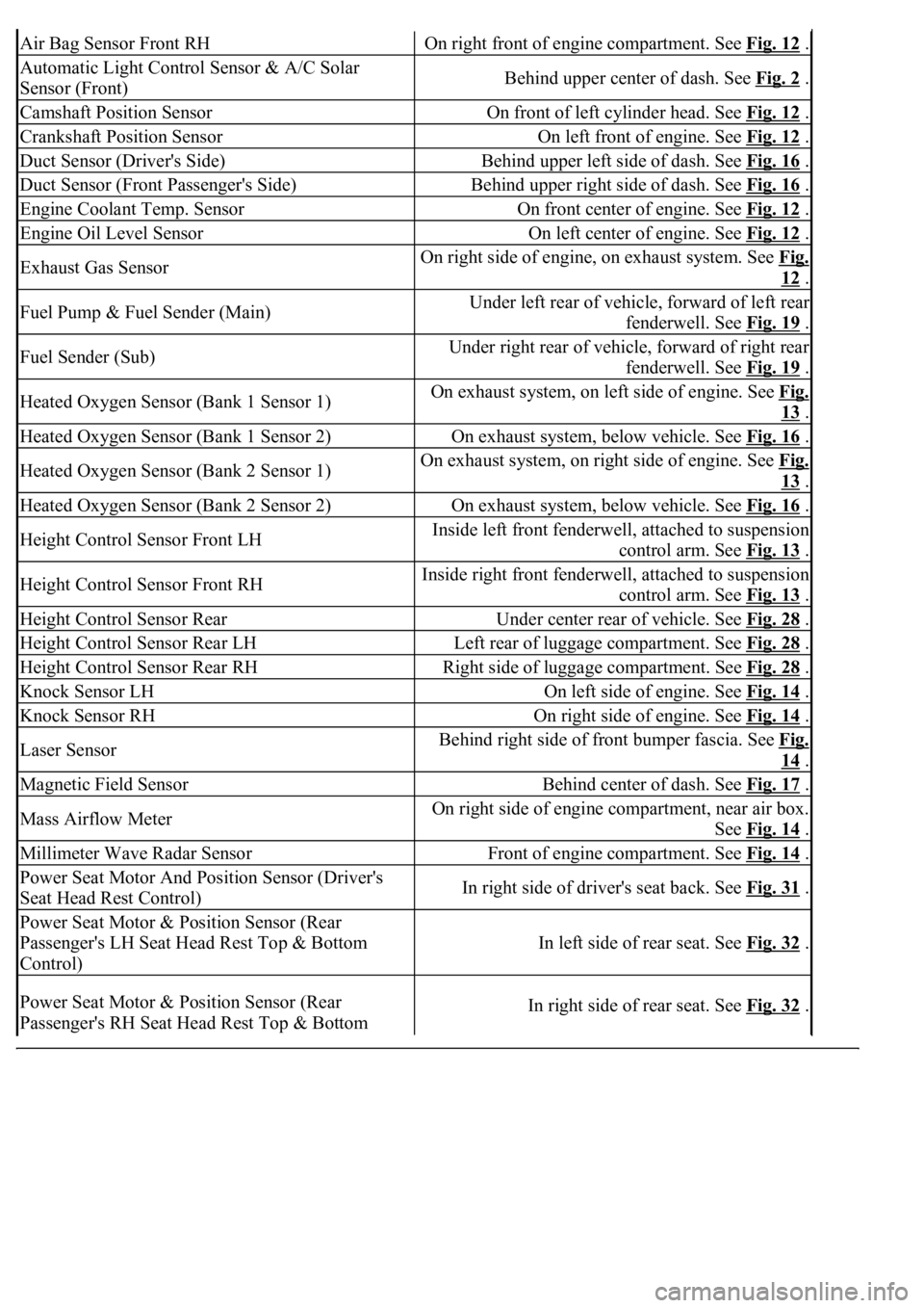
Air Bag Sensor Front RHOn right front of engine compartment. See Fig. 12 .
Automatic Light Control Sensor & A/C Solar
Sensor (Front)Behind upper center of dash. See Fig. 2 .
Camshaft Position SensorOn front of left cylinder head. See Fig. 12 .
Crankshaft Position SensorOn left front of engine. See Fig. 12 .
Duct Sensor (Driver's Side)Behind upper left side of dash. See Fig. 16 .
Duct Sensor (Front Passenger's Side)Behind upper right side of dash. See Fig. 16 .
Engine Coolant Temp. SensorOn front center of engine. See Fig. 12 .
Engine Oil Level SensorOn left center of engine. See Fig. 12 .
Exhaust Gas SensorOn right side of engine, on exhaust system. See Fig.
12 .
Fuel Pump & Fuel Sender (Main)Under left rear of vehicle, forward of left rear
fenderwell. See Fig. 19
.
Fuel Sender (Sub)Under right rear of vehicle, forward of right rear
fenderwell. See Fig. 19
.
Heated Oxygen Sensor (Bank 1 Sensor 1)On exhaust system, on left side of engine. See Fig.
13 .
Heated Oxygen Sensor (Bank 1 Sensor 2)On exhaust system, below vehicle. See Fig. 16 .
Heated Oxygen Sensor (Bank 2 Sensor 1)On exhaust system, on right side of engine. See Fig.
13 .
Heated Oxygen Sensor (Bank 2 Sensor 2)On exhaust system, below vehicle. See Fig. 16 .
Height Control Sensor Front LHInside left front fenderwell, attached to suspension
control arm. See Fig. 13
.
Height Control Sensor Front RHInside right front fenderwell, attached to suspension
control arm. See Fig. 13
.
Height Control Sensor RearUnder center rear of vehicle. See Fig. 28 .
Height Control Sensor Rear LHLeft rear of luggage compartment. See Fig. 28 .
Height Control Sensor Rear RHRight side of luggage compartment. See Fig. 28 .
Knock Sensor LHOn left side of engine. See Fig. 14 .
Knock Sensor RHOn right side of engine. See Fig. 14 .
Laser SensorBehind right side of front bumper fascia. See Fig.
14 .
Magnetic Field SensorBehind center of dash. See Fig. 17 .
Mass Airflow MeterOn right side of engine compartment, near air box.
See Fig. 14
.
Millimeter Wave Radar SensorFront of engine compartment. See Fig. 14 .
Power Seat Motor And Position Sensor (Driver's
Seat Head Rest Control)In right side of driver's seat back. See Fig. 31 .
Power Seat Motor & Position Sensor (Rear
Passenger's LH Seat Head Rest Top & Bottom
Control)
In left side of rear seat. See Fig. 32 .
Power Seat Motor & Position Sensor (Rear
Passenger's RH Seat Head Rest Top & Bottom In right side of rear seat. See Fig. 32 .
Page 2633 of 4500
Control)
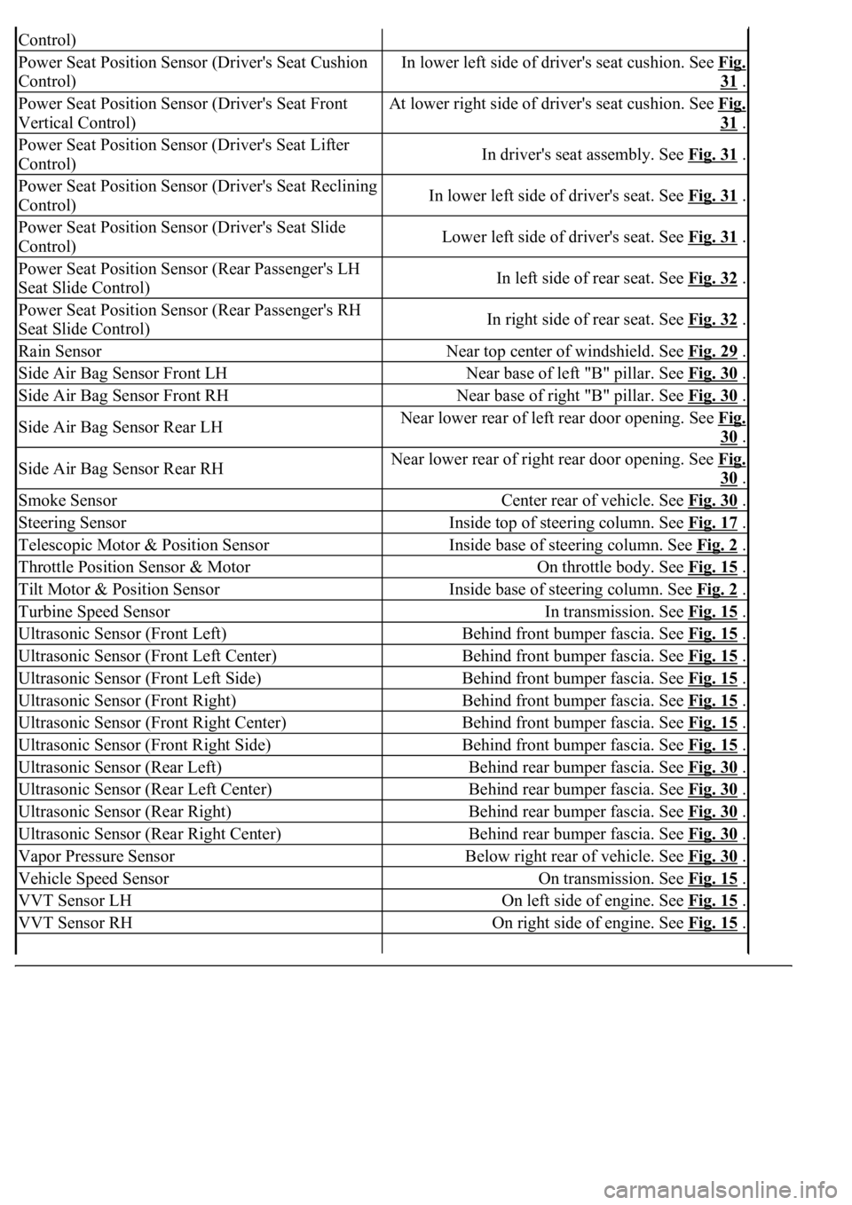
Power Seat Position Sensor (Driver's Seat Cushion
Control)In lower left side of driver's seat cushion. See Fig.
31 .
Power Seat Position Sensor (Driver's Seat Front
Vertical Control)At lower right side of driver's seat cushion. See Fig.
31 .
Power Seat Position Sensor (Driver's Seat Lifter
Control)In driver's seat assembly. See Fig. 31 .
Power Seat Position Sensor (Driver's Seat Reclining
Control)In lower left side of driver's seat. See Fig. 31 .
Power Seat Position Sensor (Driver's Seat Slide
Control)Lower left side of driver's seat. See Fig. 31 .
Power Seat Position Sensor (Rear Passenger's LH
Seat Slide Control)In left side of rear seat. See Fig. 32 .
Power Seat Position Sensor (Rear Passenger's RH
Seat Slide Control)In right side of rear seat. See Fig. 32 .
Rain SensorNear top center of windshield. See Fig. 29 .
Side Air Bag Sensor Front LHNear base of left "B" pillar. See Fig. 30 .
Side Air Bag Sensor Front RHNear base of right "B" pillar. See Fig. 30 .
Side Air Bag Sensor Rear LHNear lower rear of left rear door opening. See Fig.
30 .
Side Air Bag Sensor Rear RHNear lower rear of right rear door opening. See Fig.
30 .
Smoke SensorCenter rear of vehicle. See Fig. 30 .
Steering SensorInside top of steering column. See Fig. 17 .
Telescopic Motor & Position SensorInside base of steering column. See Fig. 2 .
Throttle Position Sensor & MotorOn throttle body. See Fig. 15 .
Tilt Motor & Position SensorInside base of steering column. See Fig. 2 .
Turbine Speed SensorIn transmission. See Fig. 15 .
Ultrasonic Sensor (Front Left)Behind front bumper fascia. See Fig. 15 .
Ultrasonic Sensor (Front Left Center)Behind front bumper fascia. See Fig. 15 .
Ultrasonic Sensor (Front Left Side)Behind front bumper fascia. See Fig. 15 .
Ultrasonic Sensor (Front Right)Behind front bumper fascia. See Fig. 15 .
Ultrasonic Sensor (Front Right Center)Behind front bumper fascia. See Fig. 15 .
Ultrasonic Sensor (Front Right Side)Behind front bumper fascia. See Fig. 15 .
Ultrasonic Sensor (Rear Left)Behind rear bumper fascia. See Fig. 30 .
Ultrasonic Sensor (Rear Left Center)Behind rear bumper fascia. See Fig. 30 .
Ultrasonic Sensor (Rear Right)Behind rear bumper fascia. See Fig. 30 .
Ultrasonic Sensor (Rear Right Center)Behind rear bumper fascia. See Fig. 30 .
Vapor Pressure SensorBelow right rear of vehicle. See Fig. 30 .
Vehicle Speed SensorOn transmission. See Fig. 15 .
VVT Sensor LHOn left side of engine. See Fig. 15 .
VVT Sensor RHOn right side of engine. See Fig. 15 .
Page 2634 of 4500
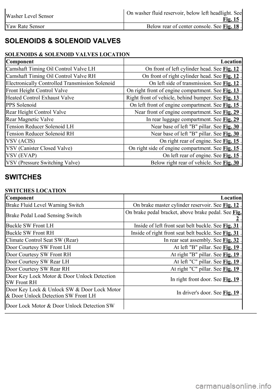
SOLENOIDS & SOLENOID VALVES LOCATION
SWITCHES LOCATION
Washer Level SensorOn washer fluid reservoir, below left headlight. See
Fig. 15
.
Yaw Rate SensorBelow rear of center console. See Fig. 18 .
ComponentLocation
Camshaft Timing Oil Control Valve LHOn front of left cylinder head. See Fig. 12 .
Camshaft Timing Oil Control Valve RHOn front of right cylinder head. See Fig. 12 .
Electronically Controlled Transmission SolenoidOn left side of transmission. See Fig. 12 .
Front Height Control ValveOn right front of engine compartment. See Fig. 13 .
Heated Control Exhaust ValveRight front of vehicle, behind bumper. See Fig. 13 .
PPS SolenoidOn left front of engine compartment. See Fig. 15 .
Rear Height Control ValveNear front of engine compartment. See Fig. 29 .
Rear Magnetic ValveIn rear luggage compartment. See Fig. 29 .
Tension Reducer Solenoid LHNear base of left "B" pillar. See Fig. 30 .
Tension Reducer Solenoid RHNear base of left "B" pillar. See Fig. 30 .
VSV (ACIS)On right rear of engine. See Fig. 15 .
VSV (Canister Closed Valve)On right side of engine compartment. See Fig. 15 .
VSV (EVAP)On left rear of engine. See Fig. 15 .
VSV (Pressure Switching Valve)Below right rear of vehicle. See Fig. 30 .
ComponentLocation
Brake Fluid Level Warning SwitchOn brake master cylinder reservoir. See Fig. 12 .
Brake Pedal Load Sensing SwitchOn brake pedal bracket, above brake pedal. See Fig.
2 .
Buckle SW Front LHInside of left front seat belt buckle. See Fig. 31 .
Buckle SW Front RHInside of right front seat belt buckle. See Fig. 31 .
Climate Control Seat SW (Rear)In rear seat assembly. See Fig. 32 .
Door Courtesy SW Front LHAt left "B" pillar. See Fig. 19 .
Door Courtesy SW Front RHAt right "B" pillar. See Fig. 19 .
Door Courtesy SW Rear LHAt left "C" pillar. See Fig. 19 .
Door Courtesy SW Rear RHAt right "C" pillar. See Fig. 19 .
Door Key Lock Motor & Door Unlock Detection
SW Front RHIn right front door. See Fig. 19 .
Door Key Lock & Unlock SW & Door Lock Motor
& Door Unlock Detection SW Front LHIn driver's door. See Fig. 19 .
Door Lock Motor & Door Unlock Detection SW
Page 2668 of 4500
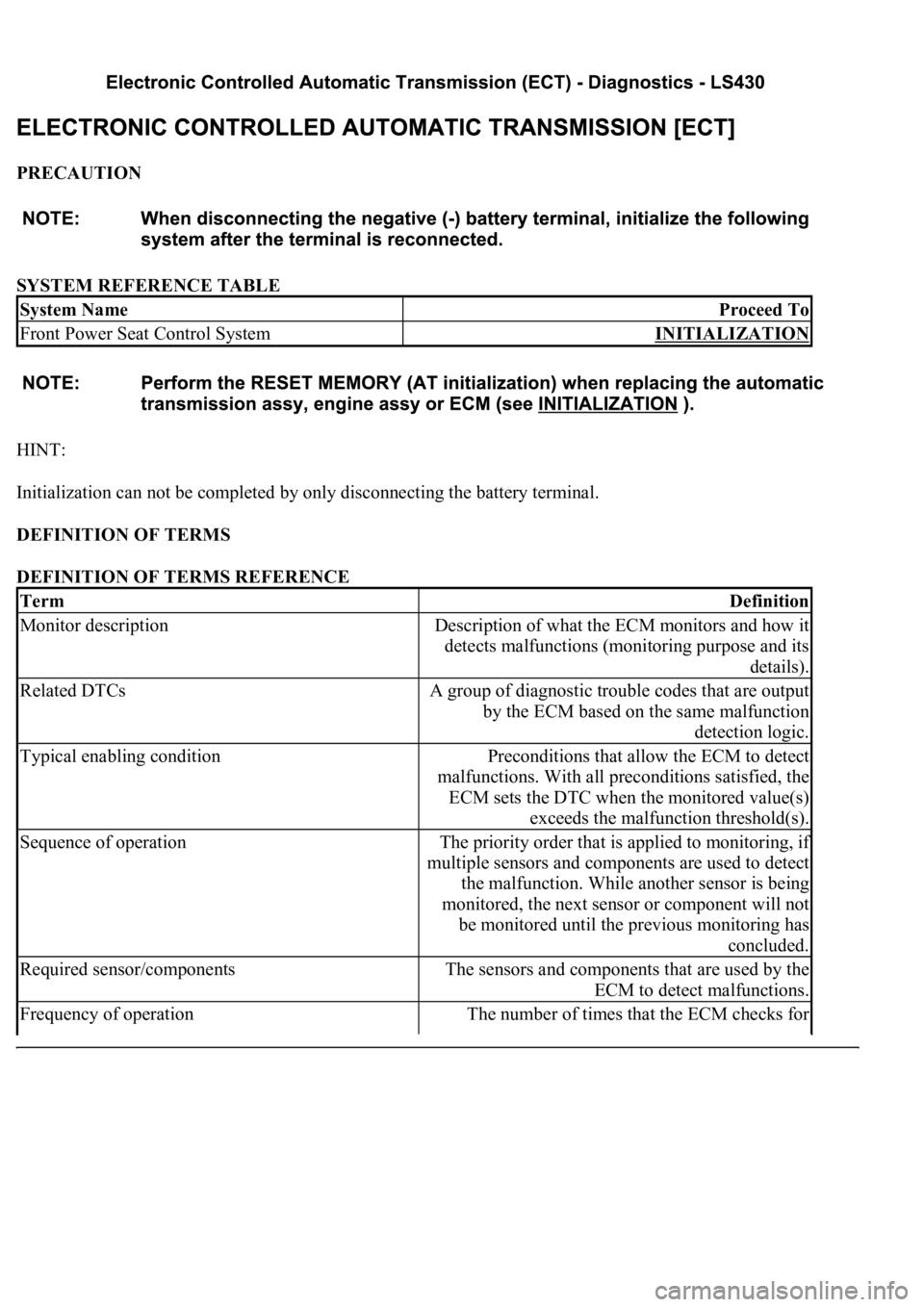
PRECAUTION
SYSTEM REFERENCE TABLE
HINT:
Initialization can not be completed by only disconnecting the battery terminal.
DEFINITION OF TERMS
DEFINITION OF TERMS REFERENCE
System NameProceed To
Front Power Seat Control SystemINITIALIZATION
TermDefinition
Monitor descriptionDescription of what the ECM monitors and how it
detects malfunctions (monitoring purpose and its
details).
Related DTCsA group of diagnostic trouble codes that are output
by the ECM based on the same malfunction
detection logic.
Typical enabling conditionPreconditions that allow the ECM to detect
malfunctions. With all preconditions satisfied, the
ECM sets the DTC when the monitored value(s)
exceeds the malfunction threshold(s).
Sequence of operationThe priority order that is applied to monitoring, if
multiple sensors and components are used to detect
the malfunction. While another sensor is being
monitored, the next sensor or component will not
be monitored until the previous monitoring has
concluded.
Required sensor/componentsThe sensors and components that are used by the
ECM to detect malfunctions.
Frequency of operationThe number of times that the ECM checks for
Page 2669 of 4500
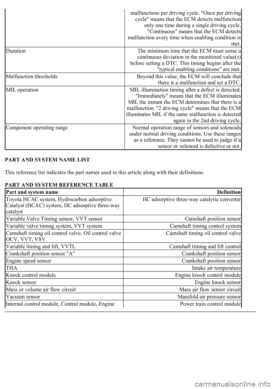
PART AND SYSTEM NAME LIST
This reference list indicates the part names used in this article along with their definitions.
PART AND SYSTEM REFERENCE TABLE
malfunctions per driving cycle. "Once per driving
cycle" means that the ECM detects malfunction
only one time during a single driving cycle.
"Continuous" means that the ECM detects
malfunction every time when enabling condition is
met.
DurationThe minimum time that the ECM must sense a
continuous deviation in the monitored value(s)
before setting a DTC. This timing begins after the
"typical enabling conditions" are met.
Malfunction thresholdsBeyond this value, the ECM will conclude that
there is a malfunction and set a DTC.
MIL operationMIL illumination timing after a defect is detected.
"Immediately" means that the ECM illuminates
MIL the instant the ECM determines that there is a
malfunction. "2 driving cycle" means that the ECM
illuminates MIL if the same malfunction is detected
again in the 2nd driving cycle.
Component operating rangeNormal operation range of sensors and solenoids
under normal driving conditions. Use these ranges
as a reference. They cannot be used to judge if a
sensor or solenoid is defective or not.
Part and system nameDefinition
Toyota HCAC system, Hydrocarbon adsorptive
Catalyst (HCAC) system, HC adsorptive three-way
catalystHC adsorptive three-way catalytic converter
Variable Valve Timing sensor, VVT sensorCamshaft position sensor
Variable valve timing system, VVT systemCamshaft timing control system
Camshaft timing oil control valve, Oil control valve
OCV, VVT, VSVCamshaft timing oil control valve
Variable timing and lift, VVTLCamshaft timing and lift control
Crankshaft position sensor "A"Crankshaft position sensor
Engine speed sensorCrankshaft position sensor
THAIntake air temperature
Knock control moduleEngine knock control module
Knock sensorEngine knock sensor
Mass or volume air flow circuitMass air flow sensor circuit
Vacuum sensorManifold air pressure sensor
Internal control module, Control module, Engine Power train control module
Page 2670 of 4500

control ECU, PCM
FC idleDeceleration fuel cut
Idle air control valveIdle speed control
VSV for CCV, Canister close valve VSV for
canister controlEvaporative emissions canister vent valve
VSV for EVAP, Vacuum switching valve assembly
No. 1, EVAP VAV, Purge VSVEvaporative emissions canister purge valve
VSV for pressure switching valve, Bypass VSVEvaporative emission pressure switching valve
Vapor pressure sensor, EVAP pressure sensor,
Evaporative emission control system pressure
sensorFuel tank pressure sensor
Charcoal canisterEvaporative emissions canister
ORVR systemOn-boad refueling vapor recovery system
Intake manifold runner controlIntake manifold tuning system
Intake manifold runner valve, IMRV, IACV (runner
valve)Intake manifold tuning valve
Intake control VSVIntake manifold tuning solenoid valve
AFSAir fuel ratio sensor
O2 sensorHeater oxygen sensor
Oxygen sensor pumping current circuitOxygen sensor output signal
Oxygen sensor reference ground circuitOxygen sensor signal ground
Accel position sensorAccelerator pedal position sensor
Throttle actuator control motor, Actuator control
motor, Electronic throttle motor, Throttle control
motorElectronic throttle actuator
Electronic throttle control system, Throttle actuator
control systemElectronic throttle control system
Throttle/pedal position sensor, Throttle/pedal
position switch, Throttle position sensor/switchThrottle position sensor
Turbo press sensorTurbocharger pressure sensor
Turbo VSVTurbocharger pressure control solenoid valve
P/S pressure switchPower-steering pressure switch
VSV for ACMActive control engine mount
Speed sensor, Vehicle speed sensor "A", Speed
sensor for skid control ECUVehicle speed sensor
ATF temperature sensor, Trans, fluid temp, sensor,
ATF temperature sensor "A"Transmission fluid temperature sensor
Electronic controlled automatic transmission, ECTElectronically controlled automatic
Intermediate shaft speed sensor "A"Counter gear speed sensor
Part and system nameDefinition
Output speed sensorOutput shaft speed sensor
<002c00510053005800570003005600530048004800470003005600480051005600520055000f0003002c005100530058005700030057005800550045004c005100480003005600530048004800470003005600480051005600520055000300050024000500
0f0003[
Speed sensor (NT), Turbine speed sensorInput turbine speed sensor