sensor LEXUS LS430 2003 Factory Repair Manual
[x] Cancel search | Manufacturer: LEXUS, Model Year: 2003, Model line: LS430, Model: LEXUS LS430 2003Pages: 4500, PDF Size: 87.45 MB
Page 4344 of 4500
a. Disconnect the sensor connector.
b. Remove the bolt and sensor.
Fig. 16: Removing Crankshaft Position Sensor
Courtesy of TOYOTA MOTOR SALES, U.S.A., INC.
3.INSTALL CRANKSHAFT POSITION SENSOR
a. Install a new sensor with the bolt.
Torque: 6.5 N.m (65 kgf.cm, 58 in.lbf)
b. Connect the sensor connector.
Page 4427 of 4500
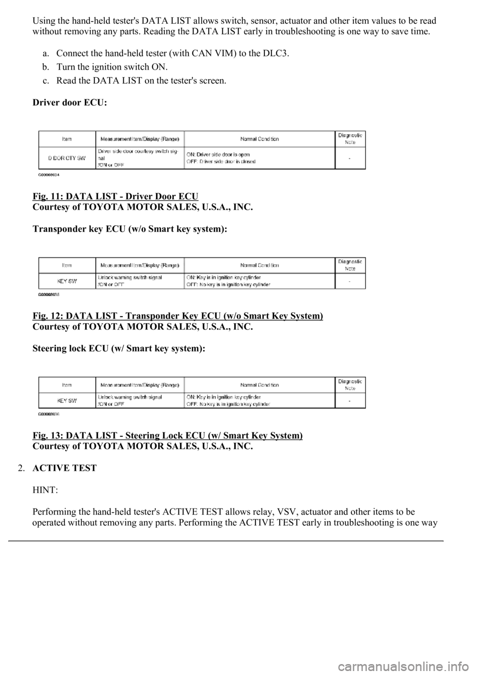
Using the hand-held tester's DATA LIST allows switch, sensor, actuator and other item values to be read
without removing any parts. Reading the DATA LIST early in troubleshooting is one way to save time.
a. Connect the hand-held tester (with CAN VIM) to the DLC3.
b. Turn the ignition switch ON.
c. Read the DATA LIST on the tester's screen.
Driver door ECU:
Fig. 11: DATA LIST
- Driver Door ECU
Courtesy of TOYOTA MOTOR SALES, U.S.A., INC.
Transponder key ECU (w/o Smart key system):
Fig. 12: DATA LIST
- Transponder Key ECU (w/o Smart Key System)
Courtesy of TOYOTA MOTOR SALES, U.S.A., INC.
Steering lock ECU (w/ Smart key system):
Fig. 13: DATA LIST
- Steering Lock ECU (w/ Smart Key System)
Courtesy of TOYOTA MOTOR SALES, U.S.A., INC.
2.ACTIVE TEST
HINT:
Performing the hand-held tester's ACTIVE TEST allows relay, VSV, actuator and other items to be
operated without removin
g any parts. Performing the ACTIVE TEST early in troubleshooting is one way
Page 4444 of 4500
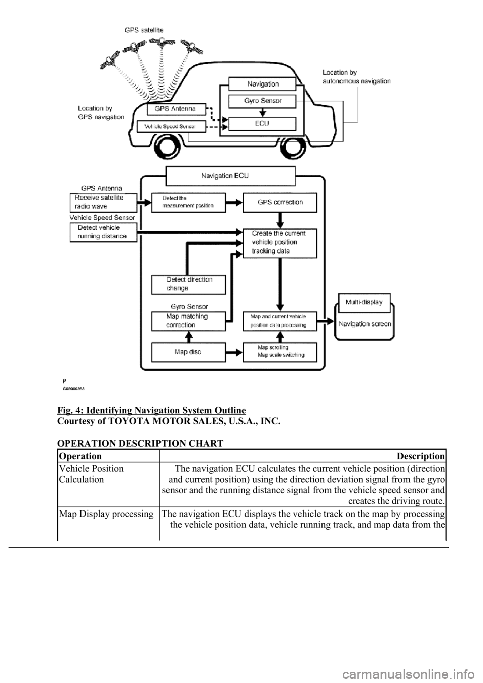
Fig. 4: Identifying Navigation System Outline
Courtesy of TOYOTA MOTOR SALES, U.S.A., INC.
OPERATION DESCRIPTION CHART
OperationDescription
Vehicle Position
CalculationThe navigation ECU calculates the current vehicle position (direction
and current position) using the direction deviation signal from the gyro
sensor and the running distance signal from the vehicle speed sensor and
creates the driving route.
Map Display processingThe navigation ECU displays the vehicle track on the map by processing
the vehicle position data, vehicle running track, and map data from the
Page 4445 of 4500
HINT:
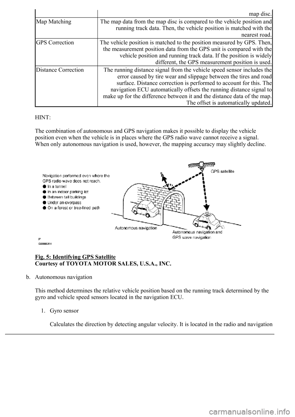
The combination of autonomous and GPS navigation makes it possible to display the vehicle
position even when the vehicle is in places where the GPS radio wave cannot receive a signal.
<003a004b00480051000300520051004f005c000300440058005700520051005200500052005800560003005100440059004c004a00440057004c005200510003004c005600030058005600480047000f0003004b0052005a0048005900480055000f000300
57004b004800030050004400530053004c0051004a00030044[ccuracy may slightly decline.
Fig. 5: Identifying GPS Satellite
Courtesy of TOYOTA MOTOR SALES, U.S.A., INC.
b. Autonomous navigation
This method determines the relative vehicle position based on the running track determined by the
gyro and vehicle speed sensors located in the navigation ECU.
1. Gyro sensor
Calculates the direction b
y detecting angular velocity. It is located in the radio and navigation
map disc.
Map MatchingThe map data from the map disc is compared to the vehicle position and
running track data. Then, the vehicle position is matched with the
nearest road.
GPS CorrectionThe vehicle position is matched to the position measured by GPS. Then,
the measurement position data from the GPS unit is compared with the
vehicle position and running track data. If the position is widely
different, the GPS measurement position is used.
Distance CorrectionThe running distance signal from the vehicle speed sensor includes the
error caused by tire wear and slippage between the tires and road
surface. Distance correction is performed to account for this. The
navigation ECU automatically offsets the running distance signal to
make up for the difference between it and the distance data of the map.
The offset is automatically updated.
Page 4446 of 4500
assy.
2. Vehicle speed sensor
Used to calculate the vehicle running distance.
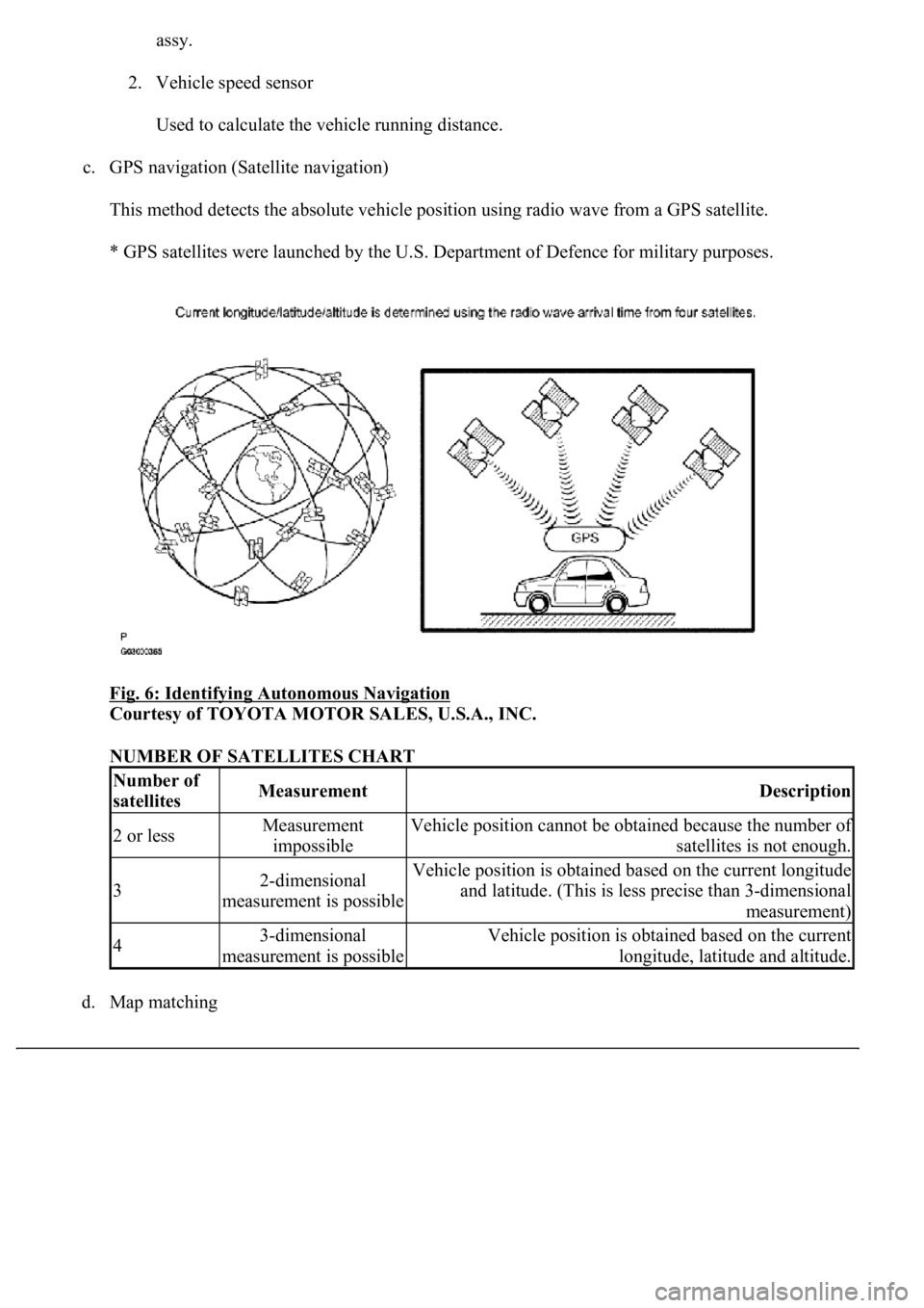
c. GPS navigation (Satellite navigation)
This method detects the absolute vehicle position using radio wave from a GPS satellite.
* GPS satellites were launched by the U.S. Department of Defence for military purposes.
Fig. 6: Identifying Autonomous Navigation
Courtesy of TOYOTA MOTOR SALES, U.S.A., INC.
NUMBER OF SATELLITES CHART
d. Map matchin
g
Number of
satellitesMeasurementDescription
2 or lessMeasurement
impossibleVehicle position cannot be obtained because the number of
satellites is not enough.
32-dimensional
measurement is possibleVehicle position is obtained based on the current longitude
and latitude. (This is less precise than 3-dimensional
measurement)
43-dimensional
measurement is possibleVehicle position is obtained based on the current
longitude, latitude and altitude.
Page 4447 of 4500
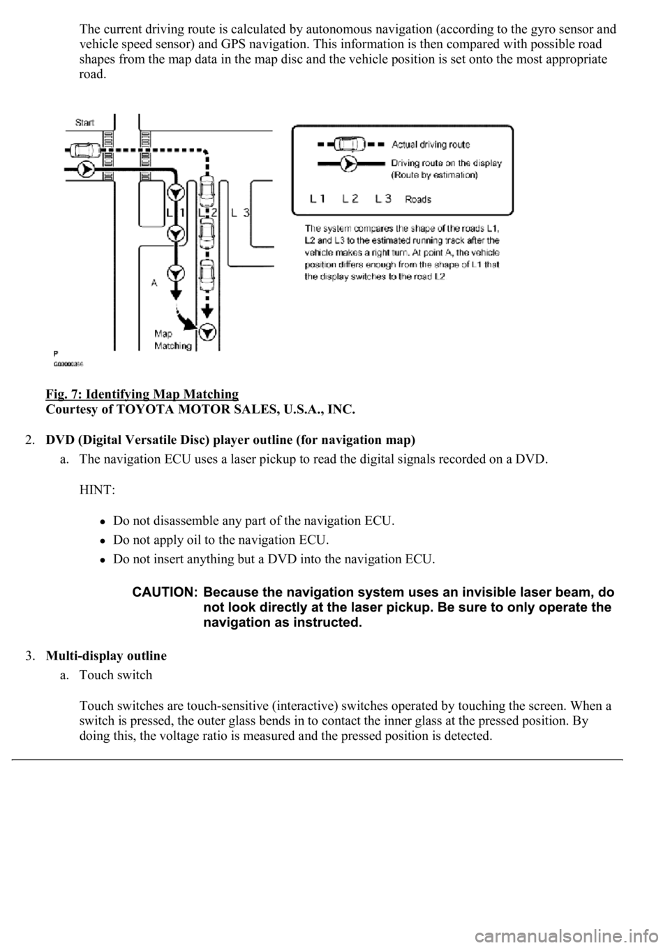
The current driving route is calculated by autonomous navigation (according to the gyro sensor and
vehicle speed sensor) and GPS navigation. This information is then compared with possible road
shapes from the map data in the map disc and the vehicle position is set onto the most appropriate
road.
Fig. 7: Identifying Map Matching
Courtesy of TOYOTA MOTOR SALES, U.S.A., INC.
2.DVD (Digital Versatile Disc) player outline (for navigation map)
a. The navigation ECU uses a laser pickup to read the digital signals recorded on a DVD.
HINT:
Do not disassemble any part of the navigation ECU.
Do not apply oil to the navigation ECU.
Do not insert anything but a DVD into the navigation ECU.
3.Multi-display outline
a. Touch switch
Touch switches are touch-sensitive (interactive) switches operated by touching the screen. When a
switch is pressed, the outer glass bends in to contact the inner glass at the pressed position. By
doing this, the voltage ratio is measured and the pressed position is detected.
Page 4469 of 4500
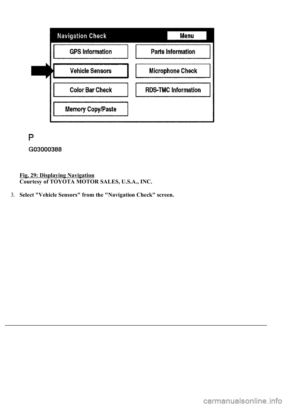
Fig. 29: Displaying Navigation
Courtesy of TOYOTA MOTOR SALES, U.S.A., INC.
3.Select "Vehicle Sensors" from the "Navigation Check" screen.
Page 4470 of 4500
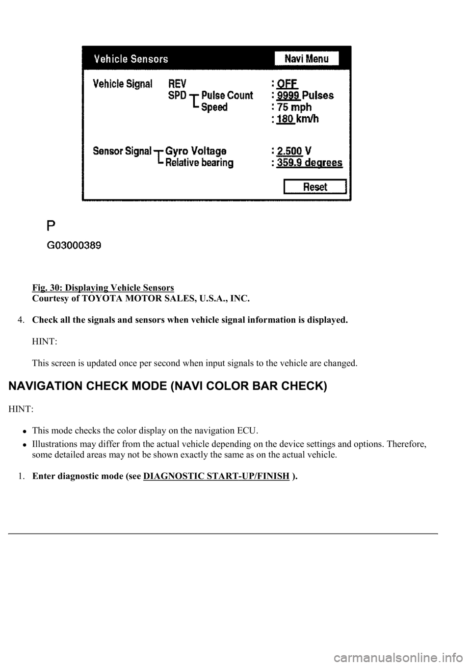
Fig. 30: Displaying Vehicle Sensors
Courtesy of TOYOTA MOTOR SALES, U.S.A., INC.
4.Check all the signals and sensors when vehicle signal information is displayed.
HINT:
This screen is updated once per second when input signals to the vehicle are changed.
HINT:
<0037004b004c00560003005000520047004800030046004b00480046004e005600030057004b0048000300460052004f0052005500030047004c00560053004f0044005c00030052005100030057004b00480003005100440059004c004a00440057004c00
5200510003002800260038001100030003[
Illustrations may differ from the actual vehicle depending on the device settings and options. Therefore,
some detailed areas may not be shown exactly the same as on the actual vehicle.
1.Enter diagnostic mode (see DIAGNOSTIC START
-UP/FINISH ).
Page 4489 of 4500

c. Vehicle Signal Check Screen
Fig. 50: Vehicle Signal Check Screen
Courtesy of TOYOTA MOTOR SALES, U.S.A., INC.
Vehicle signal
DISPLAY CHART
Sensor signal
DISPLAY CHART
HINT:
Signals are updated once per second only when vehicle sensor signals are changed.
DateThe date/time information obtained from GPS signal is displayed in Greenwich mean time
(GMT). The last 4 digits are displayed.
DisplayContents
REV/*1REV signal ON/OFF state is displayed.
SPD/*2SPD signal condition is displayed.
DisplayContents
Gyro
sensor/*3Gyro sensor output condition is displayed (when the vehicle runs straight or is
stationary, the voltage is approximately 2.5 V).
Page 4492 of 4500
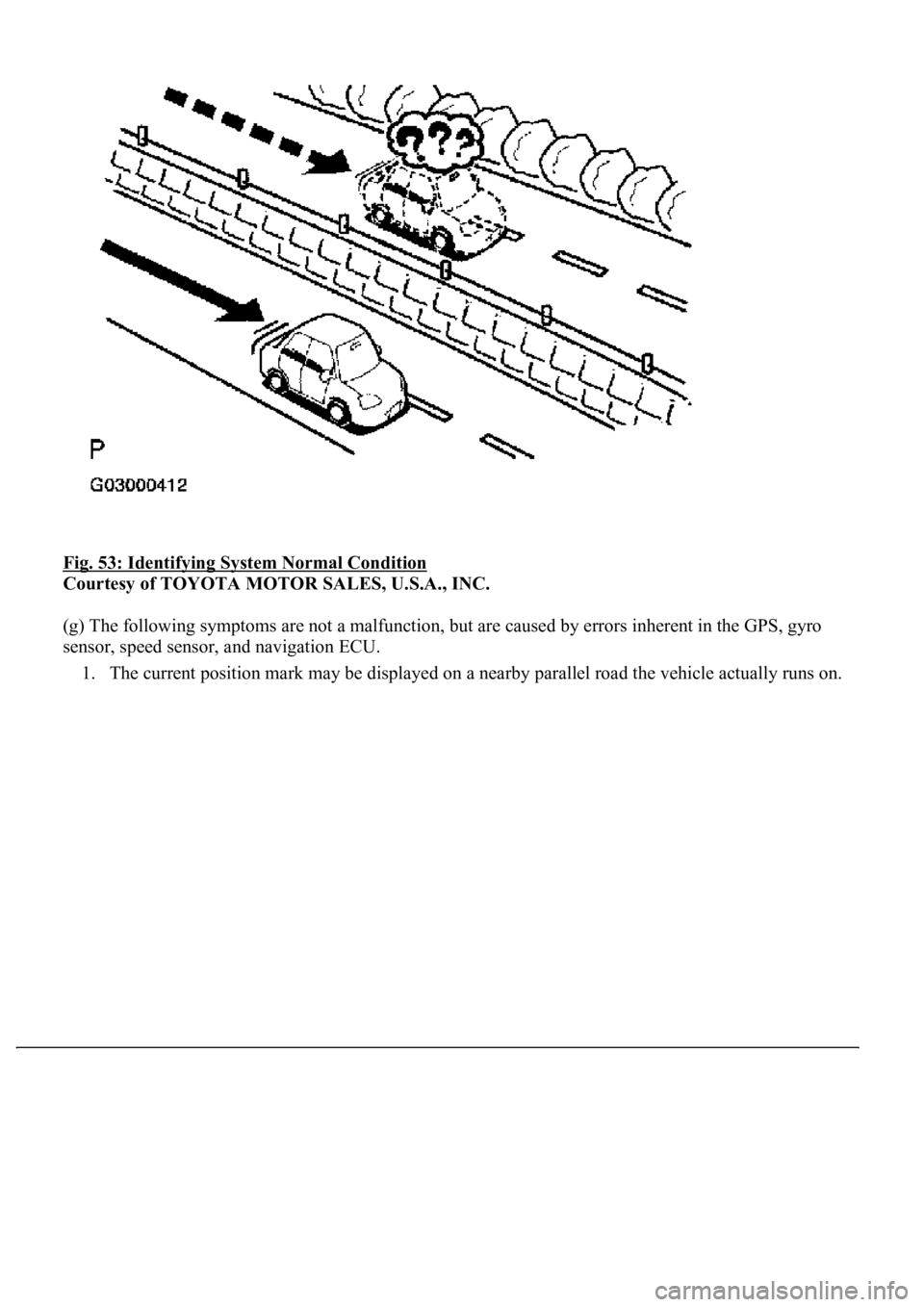
Fig. 53: Identifying System Normal Condition
Courtesy of TOYOTA MOTOR SALES, U.S.A., INC.
(g) The following symptoms are not a malfunction, but are caused by errors inherent in the GPS, gyro
sensor, speed sensor, and navigation ECU.
1. The current position mark may be displayed on a nearby parallel road the vehicle actually runs on.