sensor LEXUS LS430 2003 Factory Repair Manual
[x] Cancel search | Manufacturer: LEXUS, Model Year: 2003, Model line: LS430, Model: LEXUS LS430 2003Pages: 4500, PDF Size: 87.45 MB
Page 2784 of 4500
OK:
The torque converter clutch operates normally.
NG: REPLACE TORQUE CONVERTER CLUTCH ASSY
OK: REPAIR OR REPLACE AUTOMATIC TRANSMISSION ASSY (See COMPONENTS
)
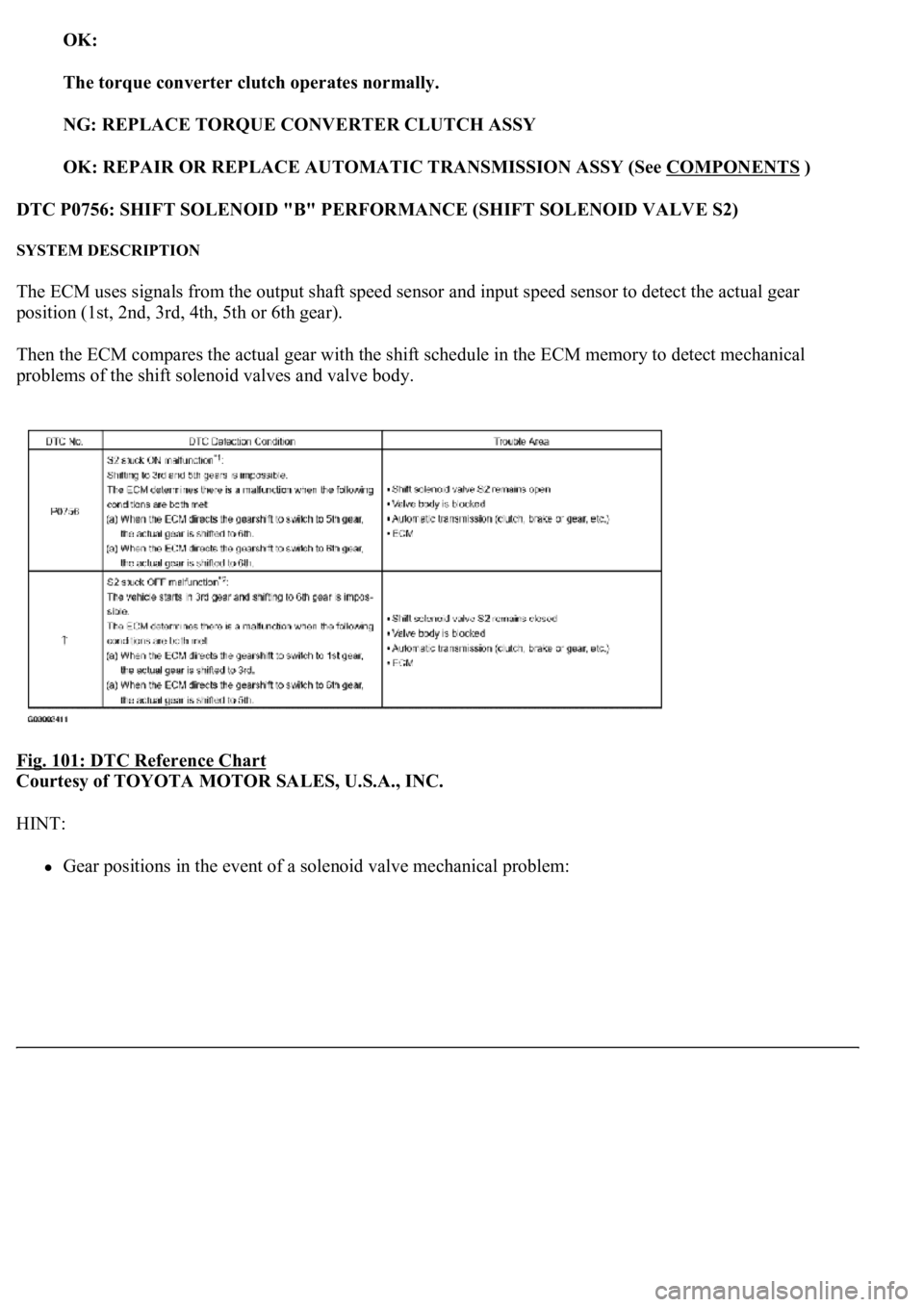
DTC P0756: SHIFT SOLENOID "B" PERFORMANCE (SHIFT SOLENOID VALVE S2)
SYSTEM DESCRIPTION
The ECM uses signals from the output shaft speed sensor and input speed sensor to detect the actual gear
position (1st, 2nd, 3rd, 4th, 5th or 6th gear).
Then the ECM compares the actual gear with the shift schedule in the ECM memory to detect mechanical
problems of the shift solenoid valves and valve body.
Fig. 101: DTC Reference Chart
Courtesy of TOYOTA MOTOR SALES, U.S.A., INC.
HINT:
Gear positions in the event of a solenoid valve mechanical problem:
Page 2785 of 4500
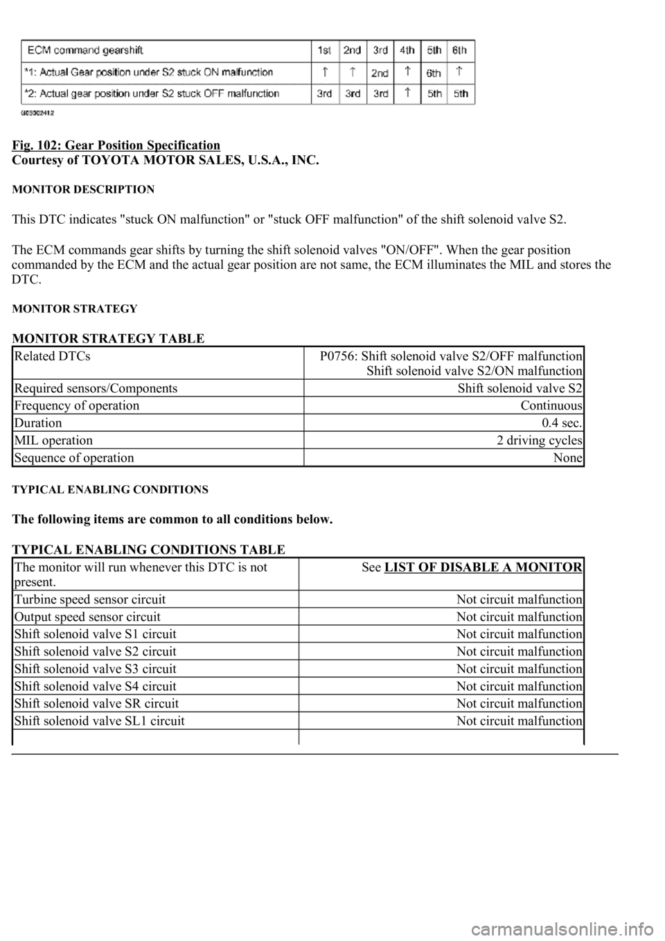
Fig. 102: Gear Position Specification
Courtesy of TOYOTA MOTOR SALES, U.S.A., INC.
MONITOR DESCRIPTION
This DTC indicates "stuck ON malfunction" or "stuck OFF malfunction" of the shift solenoid valve S2.
The ECM commands gear shifts by turning the shift solenoid valves "ON/OFF". When the gear position
commanded by the ECM and the actual gear position are not same, the ECM illuminates the MIL and stores the
DTC.
MONITOR STRATEGY
MONITOR STRATEGY TABLE
TYPICAL ENABLING CONDITIONS
The following items are common to all conditions below.
TYPICAL ENABLING CONDITIONS TABLE
Related DTCsP0756: Shift solenoid valve S2/OFF malfunction
Shift solenoid valve S2/ON malfunction
Required sensors/ComponentsShift solenoid valve S2
Frequency of operationContinuous
Duration0.4 sec.
MIL operation2 driving cycles
Sequence of operationNone
The monitor will run whenever this DTC is not
present.See LIST OF DISABLE A MONITOR
Turbine speed sensor circuitNot circuit malfunction
Output speed sensor circuitNot circuit malfunction
Shift solenoid valve S1 circuitNot circuit malfunction
Shift solenoid valve S2 circuitNot circuit malfunction
Shift solenoid valve S3 circuitNot circuit malfunction
Shift solenoid valve S4 circuitNot circuit malfunction
Shift solenoid valve SR circuitNot circuit malfunction
Shift solenoid valve SL1 circuitNot circuit malfunction
Page 2786 of 4500
OFF malfunction (A)
TYPICAL ENABLING CONDITIONS TABLE - OFF MALFUNCTION A
OFF malfunction (B)
TYPICAL ENABLING CONDITIONS TABLE - OFF MALFUNCTION B
ON malfunction (A)
TYPICAL ENABLING CONDITIONS TABLE - ON MALFUNCTION A
ON malfunction (B)
TYPICAL ENABLING CONDITIONS TABLE - ON MALFUNCTION B
TYPICAL MALFUNCTION THRESHOLDS
Shift solenoid valve SL2 circuitNot circuit malfunction
ECT (Engine coolant temperature) sensor circuitNot circuit malfunction
KCS sensor circuitNot circuit malfunction
ETCS (Electric throttle control system)Not system down
Transmission range"D"
ECT40°C (104°F) or more
Spark advance from Max. retard timing by KCS
control0° CA or more
EngineStarting
ECM selected gear1st
Vehicle speed2 km/h (1.2 mph) or more and Less than 40 km/h
(24.9 mph)
Engine speed-Turbine speed (NE-NT)50 rpm or more
ECM selected gear6th
Vehicle speed2 km/h (1.2 mph) or more
Throttle valve opening angle6.5% or more at 2,000 rpm (Conditions vary with
engine speed)
ECM selected gear5th
Vehicle speed2 km/h (1.2 mph) or more
Throttle valve opening angle6.5% or more at 2,000 rpm (Conditions vary with
engine speed)
ECM selected gear6th
Vehicle speed2 km/h (1.2 mph) or more
Throttle valve opening angle6.5% or more at 2,000 rpm (Conditions vary with
engine speed)
Page 2791 of 4500
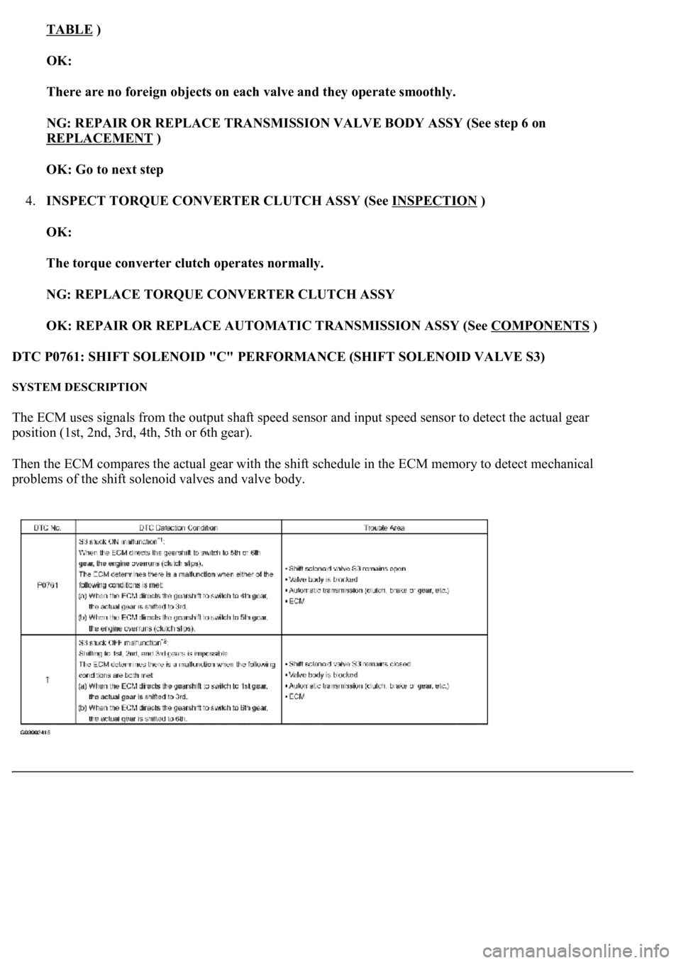
TABLE )
OK:
There are no foreign objects on each valve and they operate smoothly.
NG: REPAIR OR REPLACE TRANSMISSION VALVE BODY ASSY (See step 6 on
REPLACEMENT
)
OK: Go to next step
4.INSPECT TORQUE CONVERTER CLUTCH ASSY (See INSPECTION
)
OK:
The torque converter clutch operates normally.
NG: REPLACE TORQUE CONVERTER CLUTCH ASSY
OK: REPAIR OR REPLACE AUTOMATIC TRANSMISSION ASSY (See COMPONENTS
)
DTC P0761: SHIFT SOLENOID "C" PERFORMANCE (SHIFT SOLENOID VALVE S3)
SYSTEM DESCRIPTION
The ECM uses signals from the output shaft speed sensor and input speed sensor to detect the actual gear
position (1st, 2nd, 3rd, 4th, 5th or 6th gear).
Then the ECM compares the actual gear with the shift schedule in the ECM memory to detect mechanical
problems of the shift solenoid valves and valve body.
Page 2793 of 4500
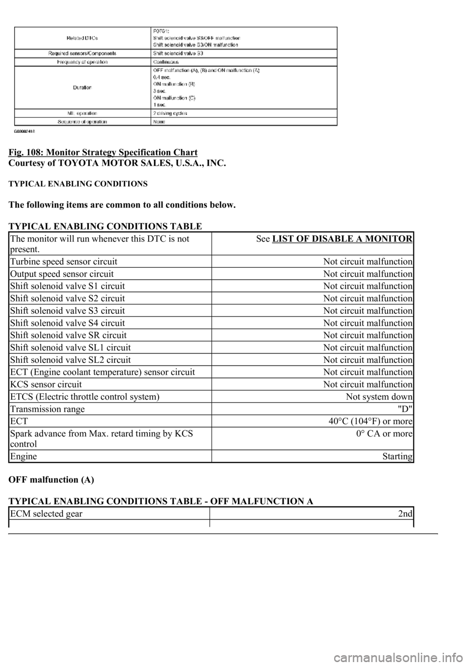
Fig. 108: Monitor Strategy Specification Chart
Courtesy of TOYOTA MOTOR SALES, U.S.A., INC.
TYPICAL ENABLING CONDITIONS
The following items are common to all conditions below.
TYPICAL ENABLING CONDITIONS TABLE
OFF malfunction (A)
TYPICAL ENABLING CONDITIONS TABLE - OFF MALFUNCTION A
The monitor will run whenever this DTC is not
present.See LIST OF DISABLE A MONITOR
Turbine speed sensor circuitNot circuit malfunction
Output speed sensor circuitNot circuit malfunction
Shift solenoid valve S1 circuitNot circuit malfunction
Shift solenoid valve S2 circuitNot circuit malfunction
Shift solenoid valve S3 circuitNot circuit malfunction
Shift solenoid valve S4 circuitNot circuit malfunction
Shift solenoid valve SR circuitNot circuit malfunction
Shift solenoid valve SL1 circuitNot circuit malfunction
Shift solenoid valve SL2 circuitNot circuit malfunction
ECT (Engine coolant temperature) sensor circuitNot circuit malfunction
KCS sensor circuitNot circuit malfunction
ETCS (Electric throttle control system)Not system down
Transmission range"D"
ECT40°C (104°F) or more
Spark advance from Max. retard timing by KCS
control0° CA or more
EngineStarting
ECM selected gear2nd
Page 2801 of 4500
There are no foreign objects on each valve and they operate smoothly.
NG: REPAIR OR REPLACE TRANSMISSION VALVE BODY ASSY (See step 6 on
REPLACEMENT
)
OK: Go to next step
5.INSPECT TORQUE CONVERTER CLUTCH ASSY (See INSPECTION
)
OK:
The torque converter clutch operates normally.
NG: REPLACE TORQUE CONVERTER CLUTCH ASSY
OK: REPAIR OR REPLACE AUTOMATIC TRANSMISSION ASSY (See COMPONENTS
)
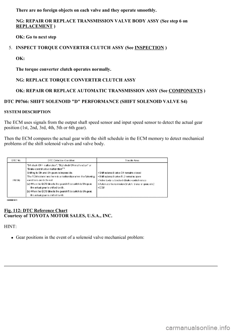
DTC P0766: SHIFT SOLENOID "D" PERFORMANCE (SHIFT SOLENOID VALVE S4)
SYSTEM DESCRIPTION
The ECM uses signals from the output shaft speed sensor and input speed sensor to detect the actual gear
position (1st, 2nd, 3rd, 4th, 5th or 6th gear).
Then the ECM compares the actual gear with the shift schedule in the ECM memory to detect mechanical
problems of the shift solenoid valves and valve body.
Fig. 112: DTC Reference Chart
Courtesy of TOYOTA MOTOR SALES, U.S.A., INC.
HINT:
Gear positions in the event of a solenoid valve mechanical problem:
Page 2802 of 4500
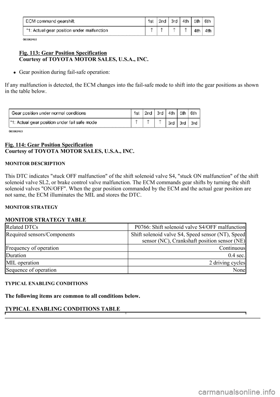
Fig. 113: Gear Position Specification
Courtesy of TOYOTA MOTOR SALES, U.S.A., INC.
Gear position during fail-safe operation:
If any malfunction is detected, the ECM changes into the fail-safe mode to shift into the gear positions as shown
in the table below.
Fig. 114: Gear Position Specification
Courtesy of TOYOTA MOTOR SALES, U.S.A., INC.
MONITOR DESCRIPTION
This DTC indicates "stuck OFF malfunction" of the shift solenoid valve S4, "stuck ON malfunction" of the shift
solenoid valve SL2, or brake control valve malfunction. The ECM commands gear shifts by turning the shift
solenoid valves "ON/OFF". When the gear position commanded by the ECM and the actual gear position are
not same, the ECM illuminates the MIL and stores the DTC.
MONITOR STRATEGY
MONITOR STRATEGY TABLE
TYPICAL ENABLING CONDITIONS
The following items are common to all conditions below.
TYPICAL ENABLING CONDITIONS TABLE
Related DTCsP0766: Shift solenoid valve S4/OFF malfunction
Required sensors/ComponentsShift solenoid valve S4, Speed sensor (NT), Speed
sensor (NC), Crankshaft position sensor (NE)
Frequency of operationContinuous
Duration0.4 sec.
MIL operation2 driving cycles
Sequence of operationNone
Page 2803 of 4500
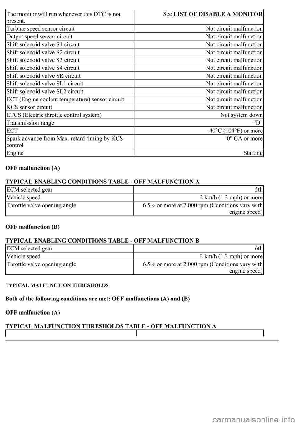
OFF malfunction (A)
TYPICAL ENABLING CONDITIONS TABLE - OFF MALFUNCTION A
OFF malfunction (B)
TYPICAL ENABLING CONDITIONS TABLE - OFF MALFUNCTION B
TYPICAL MALFUNCTION THRESHOLDS
Both of the following conditions are met: OFF malfunctions (A) and (B)
OFF malfunction (A)
TYPICAL MALFUNCTION THRESHOLDS TABLE - OFF MALFUNCTION A
The monitor will run whenever this DTC is not
present.See LIST OF DISABLE A MONITOR
Turbine speed sensor circuitNot circuit malfunction
Output speed sensor circuitNot circuit malfunction
Shift solenoid valve S1 circuitNot circuit malfunction
Shift solenoid valve S2 circuitNot circuit malfunction
Shift solenoid valve S3 circuitNot circuit malfunction
Shift solenoid valve S4 circuitNot circuit malfunction
Shift solenoid valve SR circuitNot circuit malfunction
Shift solenoid valve SL1 circuitNot circuit malfunction
Shift solenoid valve SL2 circuitNot circuit malfunction
ECT (Engine coolant temperature) sensor circuitNot circuit malfunction
KCS sensor circuitNot circuit malfunction
ETCS (Electric throttle control system)Not system down
Transmission range"D"
ECT40°C (104°F) or more
Spark advance from Max. retard timing by KCS
control0° CA or more
EngineStarting
ECM selected gear5th
Vehicle speed2 km/h (1.2 mph) or more
Throttle valve opening angle6.5% or more at 2,000 rpm (Conditions vary with
engine speed)
ECM selected gear6th
Vehicle speed2 km/h (1.2 mph) or more
Throttle valve opening angle6.5% or more at 2,000 rpm (Conditions vary with
engine speed)
Page 2812 of 4500
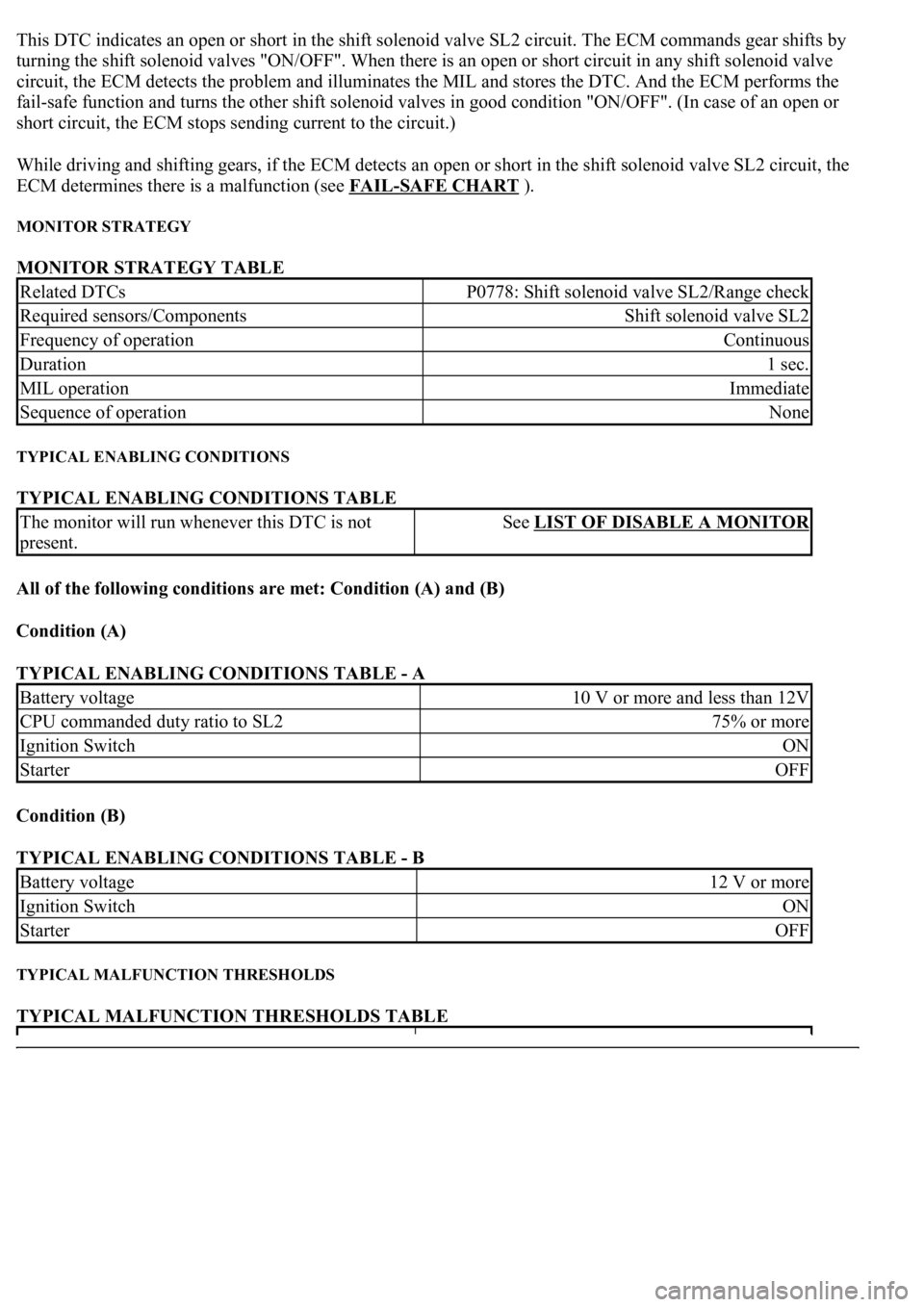
This DTC indicates an open or short in the shift solenoid valve SL2 circuit. The ECM commands gear shifts by
turning the shift solenoid valves "ON/OFF". When there is an open or short circuit in any shift solenoid valve
circuit, the ECM detects the problem and illuminates the MIL and stores the DTC. And the ECM performs the
fail-safe function and turns the other shift solenoid valves in good condition "ON/OFF". (In case of an open or
short circuit, the ECM stops sending current to the circuit.)
While driving and shifting gears, if the ECM detects an open or short in the shift solenoid valve SL2 circuit, the
ECM determines there is a malfunction (see FAIL
-SAFE CHART ).
MONITOR STRATEGY
MONITOR STRATEGY TABLE
TYPICAL ENABLING CONDITIONS
TYPICAL ENABLING CONDITIONS TABLE
All of the following conditions are met: Condition (A) and (B)
Condition (A)
TYPICAL ENABLING CONDITIONS TABLE - A
Condition (B)
TYPICAL ENABLING CONDITIONS TABLE - B
TYPICAL MALFUNCTION THRESHOLDS
TYPICAL MALFUNCTION THRESHOLDS TABLE
Related DTCsP0778: Shift solenoid valve SL2/Range check
Required sensors/ComponentsShift solenoid valve SL2
Frequency of operationContinuous
Duration1 sec.
MIL operationImmediate
Sequence of operationNone
The monitor will run whenever this DTC is not
present.See LIST OF DISABLE A MONITOR
Battery voltage10 V or more and less than 12V
CPU commanded duty ratio to SL275% or more
Ignition SwitchON
StarterOFF
Battery voltage12 V or more
Ignition SwitchON
StarterOFF
Page 2820 of 4500
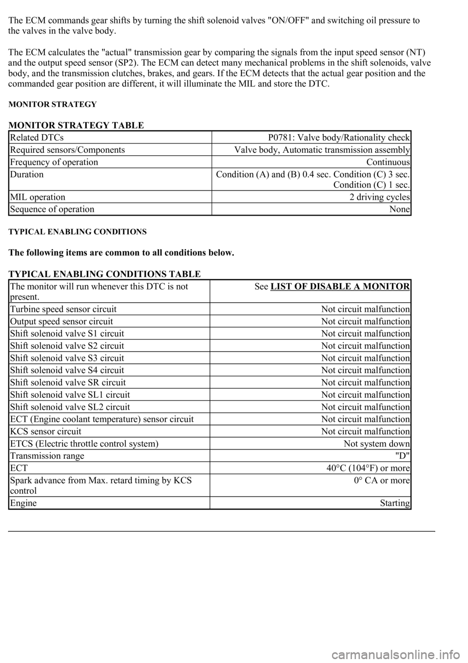
The ECM commands gear shifts by turning the shift solenoid valves "ON/OFF" and switching oil pressure to
the valves in the valve body.
The ECM calculates the "actual" transmission gear by comparing the signals from the input speed sensor (NT)
and the output speed sensor (SP2). The ECM can detect many mechanical problems in the shift solenoids, valve
body, and the transmission clutches, brakes, and gears. If the ECM detects that the actual gear position and the
commanded gear position are different, it will illuminate the MIL and store the DTC.
MONITOR STRATEGY
MONITOR STRATEGY TABLE
TYPICAL ENABLING CONDITIONS
The following items are common to all conditions below.
TYPICAL ENABLING CONDITIONS TABLE
Related DTCsP0781: Valve body/Rationality check
Required sensors/ComponentsValve body, Automatic transmission assembly
Frequency of operationContinuous
Duration<0026005200510047004c0057004c005200510003000b0024000c00030044005100470003000b0025000c00030013001100170003005600480046001100030026005200510047004c0057004c005200510003000b0026000c00030016000300560048004600
110003[
Condition (C) 1 sec.
MIL operation2 driving cycles
Sequence of operationNone
The monitor will run whenever this DTC is not
present.See LIST OF DISABLE A MONITOR
Turbine speed sensor circuitNot circuit malfunction
Output speed sensor circuitNot circuit malfunction
Shift solenoid valve S1 circuitNot circuit malfunction
Shift solenoid valve S2 circuitNot circuit malfunction
Shift solenoid valve S3 circuitNot circuit malfunction
Shift solenoid valve S4 circuitNot circuit malfunction
Shift solenoid valve SR circuitNot circuit malfunction
Shift solenoid valve SL1 circuitNot circuit malfunction
Shift solenoid valve SL2 circuitNot circuit malfunction
ECT (Engine coolant temperature) sensor circuitNot circuit malfunction
KCS sensor circuitNot circuit malfunction
ETCS (Electric throttle control system)Not system down
Transmission range"D"
ECT40°C (104°F) or more
Spark advance from Max. retard timing by KCS
control0° CA or more
EngineStarting