Temperature sensor LEXUS LS430 2003 Factory Workshop Manual
[x] Cancel search | Manufacturer: LEXUS, Model Year: 2003, Model line: LS430, Model: LEXUS LS430 2003Pages: 4500, PDF Size: 87.45 MB
Page 1602 of 4500
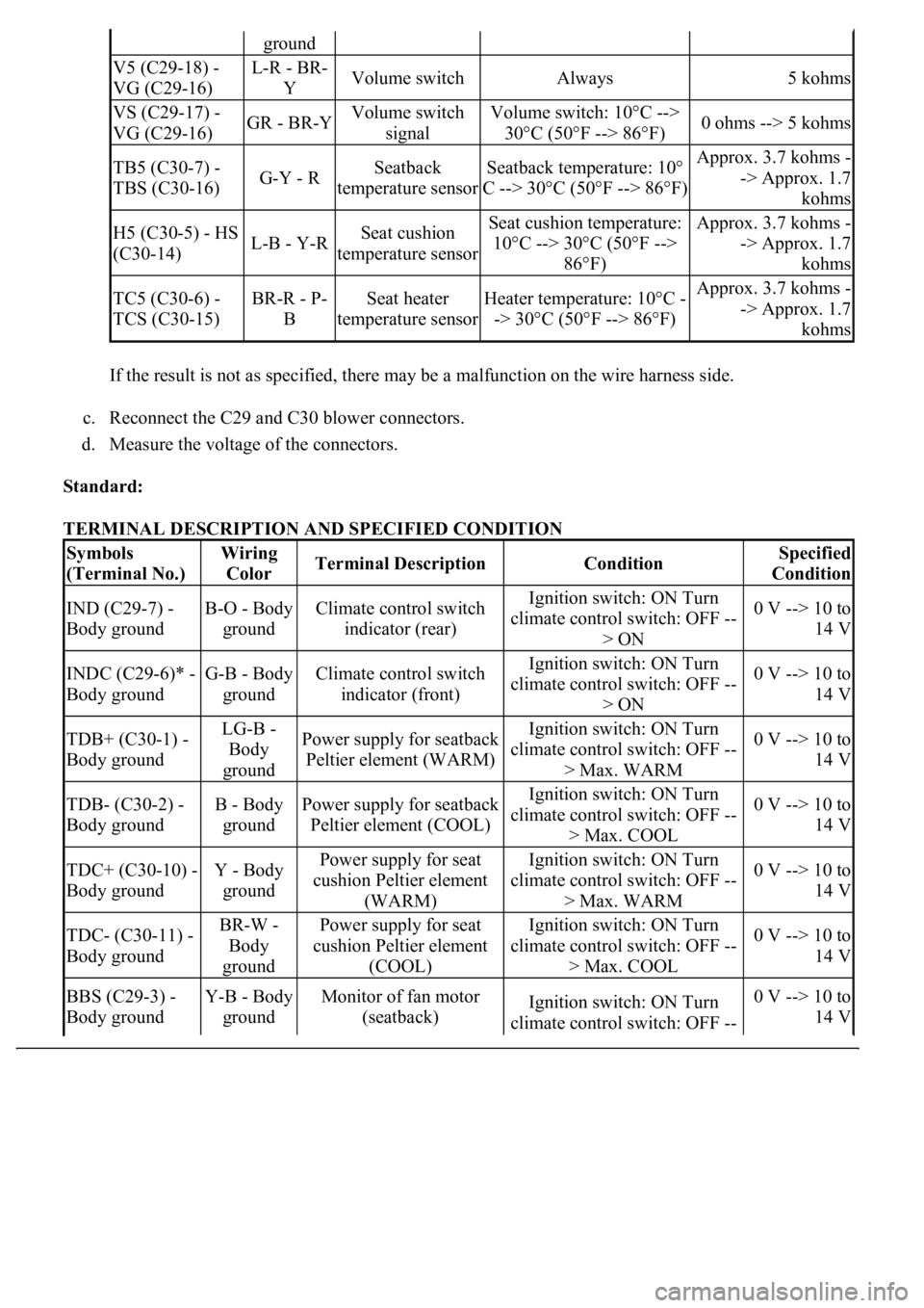
If the result is not as specified, there may be a malfunction on the wire harness side.
c. Reconnect the C29 and C30 blower connectors.
d. Measure the voltage of the connectors.
Standard:
TERMINAL DESCRIPTION AND SPECIFIED CONDITION
ground
V5 (C29-18) -
VG (C29-16)L-R - BR-
YVolume switchAlways5 kohms
VS (C29-17) -
VG (C29-16)GR - BR-YVolume switch
signalVolume switch: 10°C -->
30°C (50°F --> 86°F)0 ohms --> 5 kohms
TB5 (C30-7) -
TBS (C30-16)G-Y - RSeatback
temperature sensorSeatback temperature: 10°
C --> 30°C (50°F --> 86°F)Approx. 3.7 kohms -
-> Approx. 1.7
kohms
H5 (C30-5) - HS
(C30-14)L-B - Y-RSeat cushion
temperature sensorSeat cushion temperature:
10°C --> 30°C (50°F -->
86°F)Approx. 3.7 kohms -
-> Approx. 1.7
kohms
TC5 (C30-6) -
TCS (C30-15)BR-R - P-
BSeat heater
temperature sensorHeater temperature: 10°C -
-> 30°C (50°F --> 86°F)Approx. 3.7 kohms -
-> Approx. 1.7
kohms
Symbols
(Terminal No.)Wiring
ColorTerminal DescriptionConditionSpecified
Condition
IND (C29-7) -
Body groundB-O - Body
groundClimate control switch
indicator (rear)Ignition switch: ON Turn
climate control switch: OFF --
> ON0 V --> 10 to
14 V
INDC (C29-6)* -
Body groundG-B - Body
groundClimate control switch
indicator (front)Ignition switch: ON Turn
climate control switch: OFF --
> ON0 V --> 10 to
14 V
TDB+ (C30-1) -
Body groundLG-B -
Body
groundPower supply for seatback
Peltier element (WARM)Ignition switch: ON Turn
climate control switch: OFF --
> Max. WARM0 V --> 10 to
14 V
TDB- (C30-2) -
Body groundB - Body
groundPower supply for seatback
Peltier element (COOL)Ignition switch: ON Turn
climate control switch: OFF --
> Max. COOL0 V --> 10 to
14 V
TDC+ (C30-10) -
Body groundY - Body
groundPower supply for seat
cushion Peltier element
(WARM)Ignition switch: ON Turn
climate control switch: OFF --
> Max. WARM0 V --> 10 to
14 V
TDC- (C30-11) -
Body groundBR-W -
Body
groundPower supply for seat
cushion Peltier element
(COOL)Ignition switch: ON Turn
climate control switch: OFF --
> Max. COOL0 V --> 10 to
14 V
BBS (C29-3) -
Body groundY-B - Body
groundMonitor of fan motor
(seatback)Ignition switch: ON Turn
climate control switch: OFF --0 V --> 10 to
14 V
Page 1743 of 4500
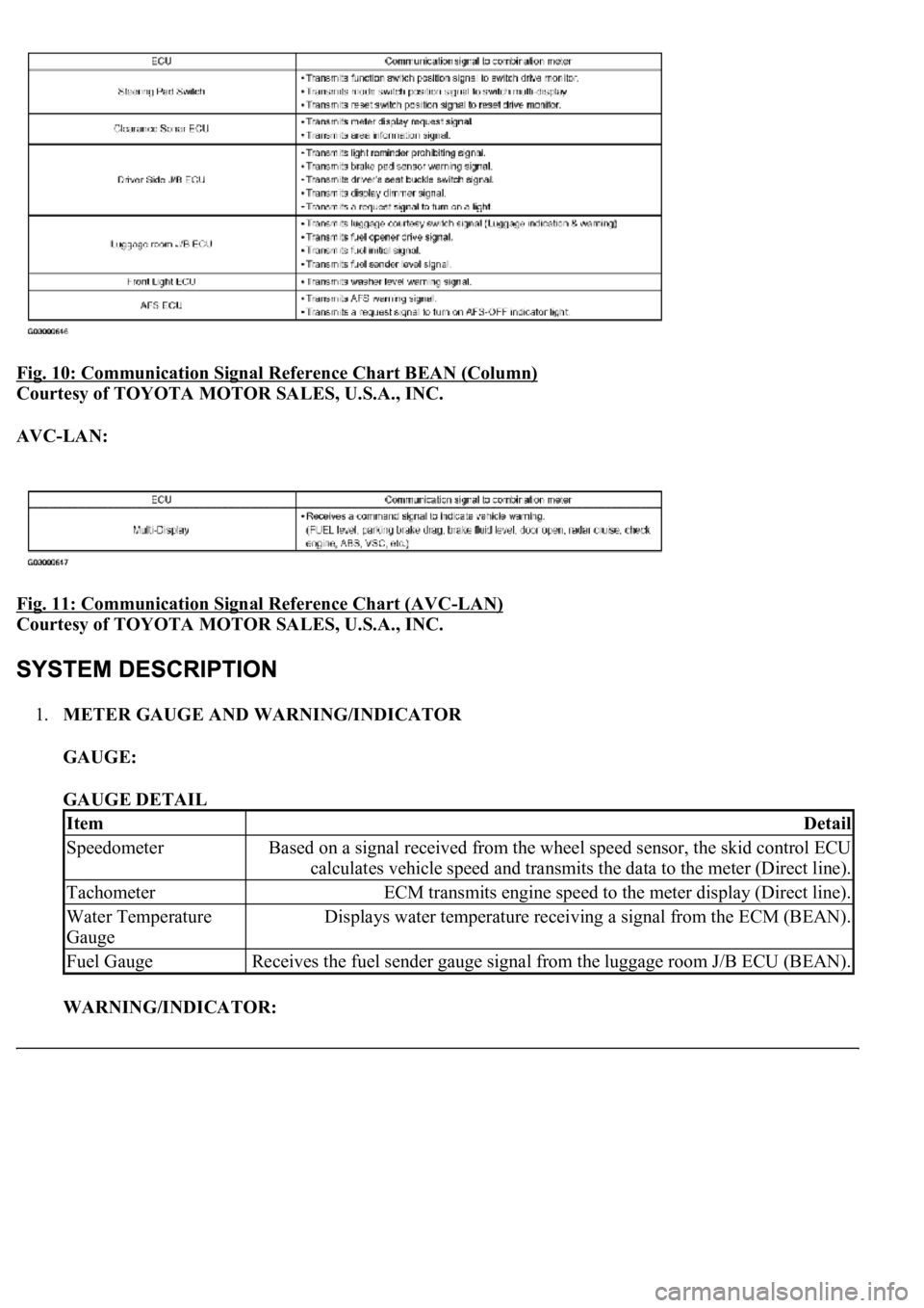
Fig. 10: Communication Signal Reference Chart BEAN (Column)
Courtesy of TOYOTA MOTOR SALES, U.S.A., INC.
AVC-LAN:
Fig. 11: Communication Signal Reference Chart (AVC
-LAN)
Courtesy of TOYOTA MOTOR SALES, U.S.A., INC.
1.METER GAUGE AND WARNING/INDICATOR
GAUGE:
GAUGE DETAIL
WARNING/INDICATOR:
ItemDetail
SpeedometerBased on a signal received from the wheel speed sensor, the skid control ECU
calculates vehicle speed and transmits the data to the meter (Direct line).
TachometerECM transmits engine speed to the meter display (Direct line).
Water Temperature
GaugeDisplays water temperature receiving a signal from the ECM (BEAN).
Fuel GaugeReceives the fuel sender gauge signal from the luggage room J/B ECU (BEAN).
Page 1779 of 4500
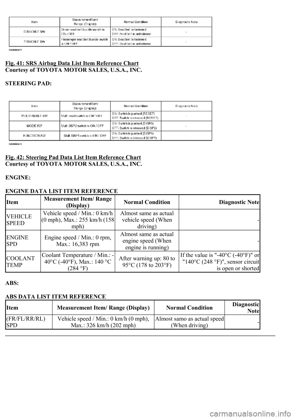
Fig. 41: SRS Airbag Data List Item Reference Chart
Courtesy of TOYOTA MOTOR SALES, U.S.A., INC.
STEERING PAD:
Fig. 42: Steering Pad Data List Item Reference Chart
Courtesy of TOYOTA MOTOR SALES, U.S.A., INC.
ENGINE:
ENGINE DATA LIST ITEM REFERENCE
ABS:
ABS DATA LIST ITEM REFERENCE
ItemMeasurement Item/ Range
(Display)Normal ConditionDiagnostic Note
VEHICLE
SPEEDVehicle speed / Min.: 0 km/h
(0 mph), Max.: 255 km/h (158
mph)Almost same as actual
vehicle speed (When
driving)
-
ENGINE
SPDEngine speed / Min.: 0 rpm,
Max.: 16,383 rpmAlmost same as actual
engine speed (When
engine is running)
-
COOLANT
TEMPCoolant Temperature / Min.: -
40°C (-40°F), Max.: 140 °C
(284 °F)After warning up: 80 to
95°C (178 to 203°F)If the value is "-40°C (-40°F)" or
"140°C (248 °F)", sensor circuit
is open or shorted
ItemMeasurement Item/ Range (Display)Normal ConditionDiagnostic
Note
(FR/FL/RR/RL)
SPDVehicle speed / Min.: 0 km/h (0 mph),
Max.: 326 km/h (202 mph)Almost samo as actual speed
(When driving)-
Page 1810 of 4500
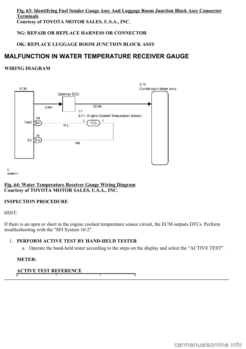
Fig. 63: Identifying Fuel Sender Gauge Assy And Luggage Room Junction Block Assy Connector
Terminals
Courtesy of TOYOTA MOTOR SALES, U.S.A., INC.
NG: REPAIR OR REPLACE HARNESS OR CONNECTOR
OK: REPLACE LUGGAGE ROOM JUNCTION BLOCK ASSY
WIRING DIAGRAM
Fig. 64: Water Temperature Receiver Gauge Wiring Diagram
Courtesy of TOYOTA MOTOR SALES, U.S.A., INC.
INSPECTION PROCEDURE
HINT:
If there is an open or short in the engine coolant temperature sensor circuit, the ECM outputs DTCs. Perform
troubleshooting with the "SFI System 10-2".
1.PERFORM ACTIVE TEST BY HAND-HELD TESTER
a. Operate the hand-held tester according to the steps on the display and select the "ACTIVE TEST".
METER:
ACTIVE TEST REFERENCE
Page 1811 of 4500
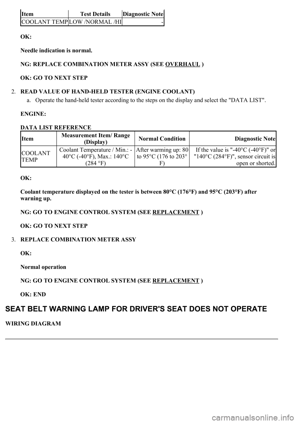
OK:
Needle indication is normal.
NG: REPLACE COMBINATION METER ASSY (SEE OVERHAUL
)
OK: GO TO NEXT STEP
2.READ VALUE OF HAND-HELD TESTER (ENGINE COOLANT)
a. Operate the hand-held tester according to the steps on the display and select the "DATA LIST".
ENGINE:
DATA LIST REFERENCE
OK:
Coolant temperature displayed on the tester is between 80°C (176°F) and 95°C (203°F) after
warning up.
NG: GO TO ENGINE CONTROL SYSTEM (SEE REPLACEMENT
)
OK: GO TO NEXT STEP
3.REPLACE COMBINATION METER ASSY
OK:
Normal operation
NG: GO TO ENGINE CONTROL SYSTEM (SEE REPLACEMENT
)
OK: END
WIRING DIAGRAM
ItemTest DetailsDiagnostic Note
COOLANT TEMPLOW /NORMAL /HI-
ItemMeasurement Item/ Range
(Display)Normal ConditionDiagnostic Note
COOLANT
TEMPCoolant Temperature / Min.: -
40°C (-40°F), Max.: 140°C
(284 °F)After warming up: 80
to 95°C (176 to 203°
F)If the value is "-40°C (-40°F)" or
"140°C (284°F)", sensor circuit is
open or shorted.
Page 1858 of 4500
ON-VEHICLE INSPECTION
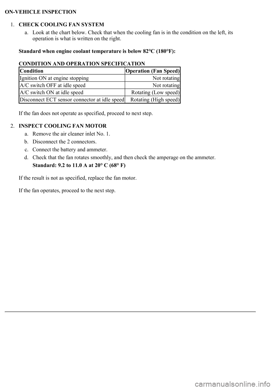
1.CHECK COOLING FAN SYSTEM
a. Look at the chart below. Check that when the cooling fan is in the condition on the left, its
operation is what is written on the right.
Standard when engine coolant temperature is below 82°C (180°F):
CONDITION AND OPERATION SPECIFICATION
If the fan does not operate as specified, proceed to next step.
2.INSPECT COOLING FAN MOTOR
a. Remove the air cleaner inlet No. 1.
b. Disconnect the 2 connectors.
c. Connect the battery and ammeter.
d. Check that the fan rotates smoothly, and then check the amperage on the ammeter.
Standard: 9.2 to 11.0 A at 20° C (68° F)
If the result is not as specified, replace the fan motor.
If the fan operates, proceed to the next step.
ConditionOperation (Fan Speed)
Ignition ON at engine stoppingNot rotating
A/C switch OFF at idle speedNot rotating
A/C switch ON at idle speedRotating (Low speed)
Disconnect ECT sensor connector at idle speedRotating (High speed)
Page 2407 of 4500
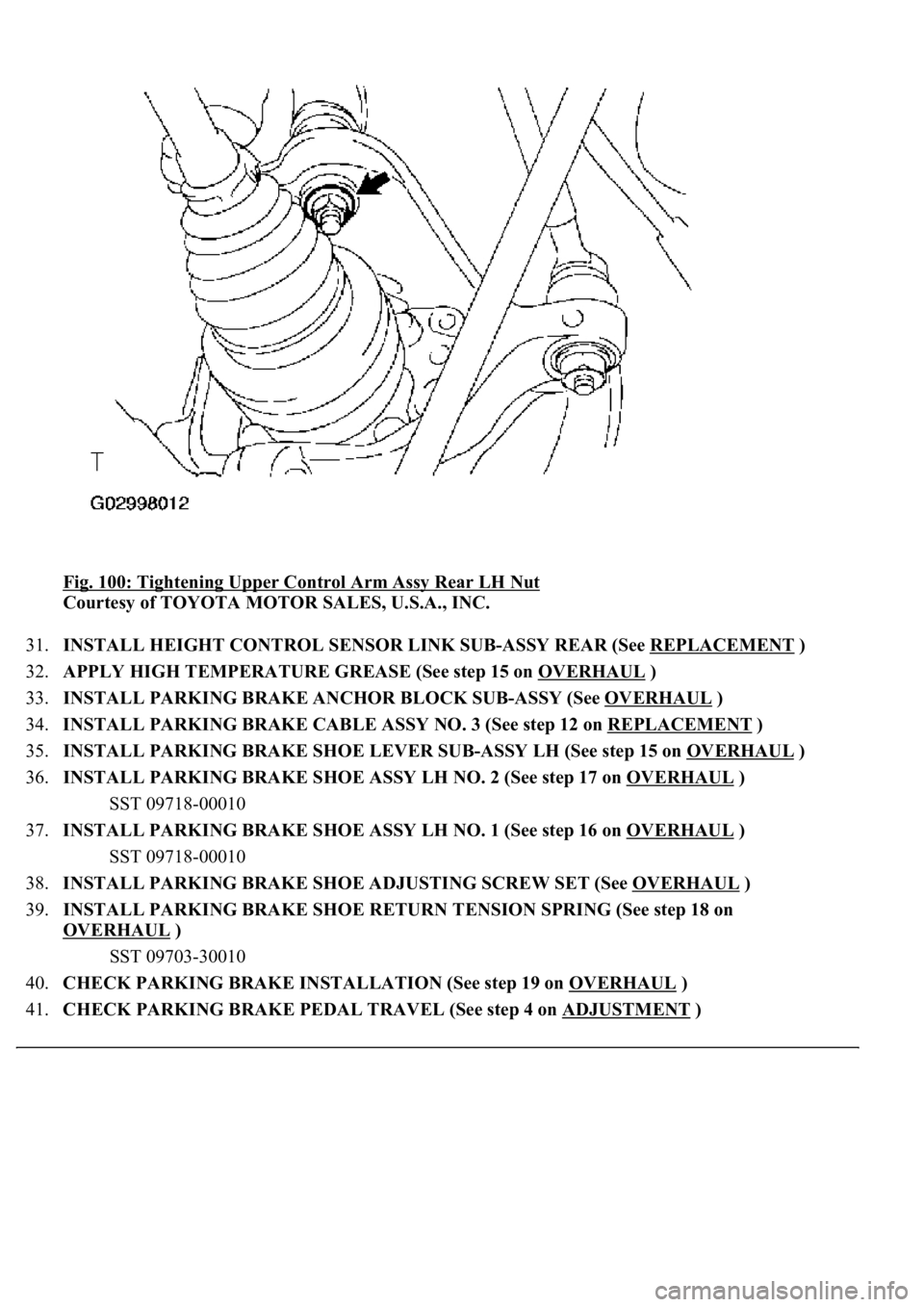
Fig. 100: Tightening Upper Control Arm Assy Rear LH Nut
Courtesy of TOYOTA MOTOR SALES, U.S.A., INC.
31.INSTALL HEIGHT CONTROL SENSOR LINK SUB-ASSY REAR (See REPLACEMENT
)
32.APPLY HIGH TEMPERATURE GREASE (See step 15 on OVERHAUL
)
33.INSTALL PARKING BRAKE ANCHOR BLOCK SUB-ASSY (See OVERHAUL
)
34.INSTALL PARKING BRAKE CABLE ASSY NO. 3 (See step 12 on REPLACEMENT
)
35.INSTALL PARKING BRAKE SHOE LEVER SUB-ASSY LH (See step 15 on OVERHAUL
)
36.INSTALL PARKING BRAKE SHOE ASSY LH NO. 2 (See step 17 on OVERHAUL
)
SST 09718-00010
37.INSTALL PARKING BRAKE SHOE ASSY LH NO. 1 (See step 16 on OVERHAUL
)
SST 09718-00010
38.INSTALL PARKING BRAKE SHOE ADJUSTING SCREW SET (See OVERHAUL
)
39.INSTALL PARKING BRAKE SHOE RETURN TENSION SPRING (See step 18 on
OVERHAUL
)
SST 09703-30010
40.CHECK PARKING BRAKE INSTALLATION (See step 19 on OVERHAUL
)
41.CHECK PARKING BRAKE PEDAL TRAVEL (See step 4 on ADJUSTMENT
)
Page 2414 of 4500
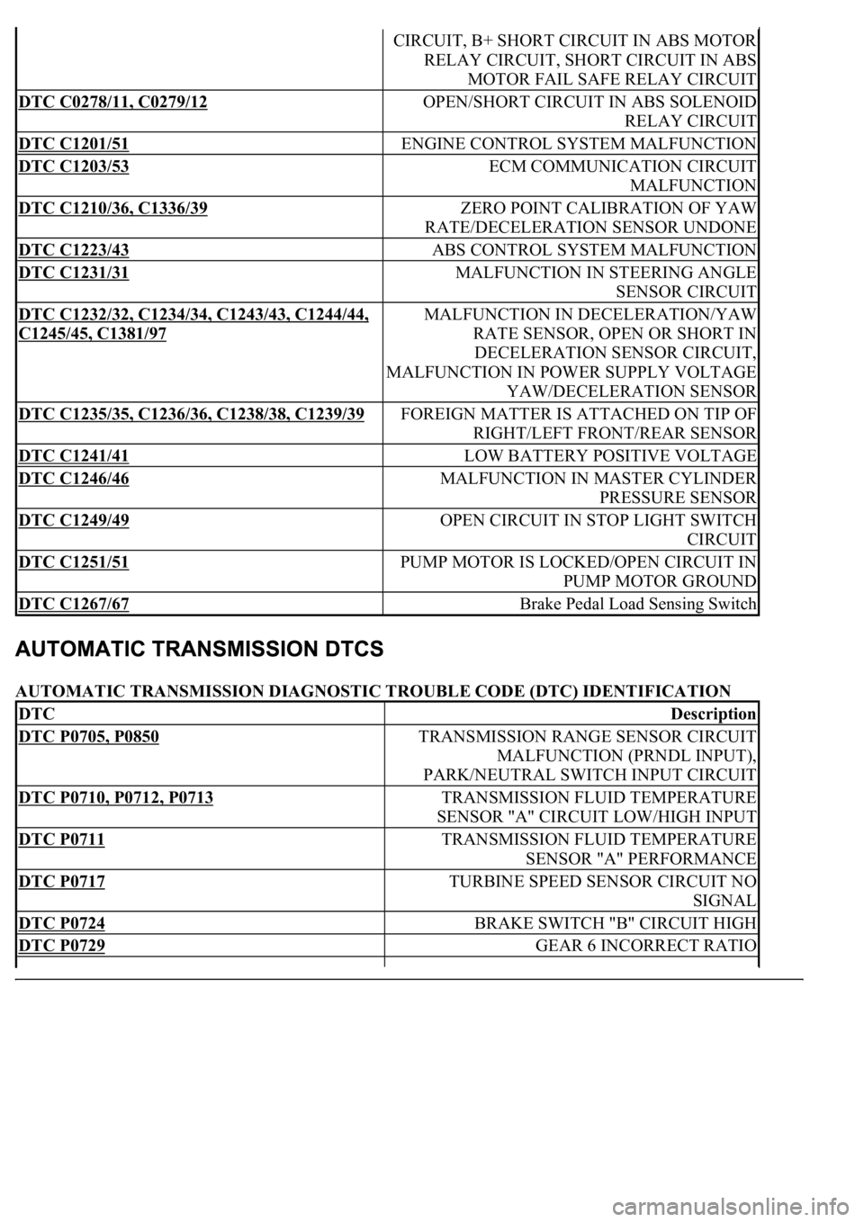
AUTOMATIC TRANSMISSION DIAGNOSTIC TROUBLE CODE (DTC) IDENTIFICATION
CIRCUIT, B+ SHORT CIRCUIT IN ABS MOTOR
RELAY CIRCUIT, SHORT CIRCUIT IN ABS
MOTOR FAIL SAFE RELAY CIRCUIT
DTC C0278/11, C0279/12 OPEN/SHORT CIRCUIT IN ABS SOLENOID
RELAY CIRCUIT
DTC C1201/51 ENGINE CONTROL SYSTEM MALFUNCTION
DTC C1203/53 ECM COMMUNICATION CIRCUIT
MALFUNCTION
DTC C1210/36, C1336/39 ZERO POINT CALIBRATION OF YAW
RATE/DECELERATION SENSOR UNDONE
DTC C1223/43 ABS CONTROL SYSTEM MALFUNCTION
DTC C1231/31 MALFUNCTION IN STEERING ANGLE
SENSOR CIRCUIT
DTC C1232/32, C1234/34, C1243/43, C1244/44,
C1245/45, C1381/97
MALFUNCTION IN DECELERATION/YAW
RATE SENSOR, OPEN OR SHORT IN
DECELERATION SENSOR CIRCUIT,
MALFUNCTION IN POWER SUPPLY VOLTAGE
YAW/DECELERATION SENSOR
DTC C1235/35, C1236/36, C1238/38, C1239/39 FOREIGN MATTER IS ATTACHED ON TIP OF
RIGHT/LEFT FRONT/REAR SENSOR
DTC C1241/41 LOW BATTERY POSITIVE VOLTAGE
DTC C1246/46 MALFUNCTION IN MASTER CYLINDER
PRESSURE SENSOR
DTC C1249/49 OPEN CIRCUIT IN STOP LIGHT SWITCH
CIRCUIT
DTC C1251/51 PUMP MOTOR IS LOCKED/OPEN CIRCUIT IN
PUMP MOTOR GROUND
DTC C1267/67 Brake Pedal Load Sensing Switch
DTCDescription
DTC P0705, P0850 TRANSMISSION RANGE SENSOR CIRCUIT
MALFUNCTION (PRNDL INPUT),
PARK/NEUTRAL SWITCH INPUT CIRCUIT
DTC P0710, P0712, P0713 TRANSMISSION FLUID TEMPERATURE
SENSOR "A" CIRCUIT LOW/HIGH INPUT
DTC P0711 TRANSMISSION FLUID TEMPERATURE
SENSOR "A" PERFORMANCE
DTC P0717 TURBINE SPEED SENSOR CIRCUIT NO
SIGNAL
DTC P0724 BRAKE SWITCH "B" CIRCUIT HIGH
DTC P0729 GEAR 6 INCORRECT RATIO
Page 2421 of 4500

HVAC DIAGNOSTIC TROUBLE CODE (DTC) IDENTIFICATION
LIGHTING SYSTEM DIAGNOSTIC TROUBLE CODE (DTC) IDENTIFICATION
SENSOR/SWITCH "D"/"E" VOLTAGE
CORRELATION
DTC P2121 THROTTLE/PEDAL POSITION
SENSOR/SWITCH "D" CIRCUIT
RANGE/PERFORMANCE
DTC U0001 HIGH SPEED CAN COMMUNICATION
CIRCUIT
DTCDescription
DTC B1411 ROOM TEMPERATURE SENSOR CIRCUIT
DTC B1412 AMBIENT TEMPERATURE SENSOR CIRCUIT
DTC B1413 EVAPORATOR TEMPERATURE SENSOR CIRCUIT
DTC B1415 AIR DUCT SENSOR CIRCUIT (DRIVER SIDE)
DTC B1416 AIR DUCT SENSOR CIRCUIT (PASSENGER SIDE)
DTC B1418 EMISSION GAS SENSOR CIRCUIT
DTC B1421 SOLAR SENSOR CIRCUIT (PASSENGER SIDE)
DTC B1423 PRESSURE SWITCH CIRCUIT
DTC B1424 SOLAR SENSOR CIRCUIT (DRIVER SIDE)
DTC B1428 REAR SOLAR SENSOR CIRCUIT
DTC B1432 AIR INLET DAMPER POSITION SENSOR CIRCUIT
DTC B1434 MAX COOL DAMPER POSITION SENSOR CIRCUIT (DRIVER SIDE)
DTC B1435 MAX COOL DAMPER POSITION SENSOR CIRCUIT (PASSENGER SIDE)
DTC B1442 AIR INLET DAMPER CONTROL SERVOMOTOR CIRCUIT
DTC B1451 COMPRESSOR SOLENOID CIRCUIT
DTC B1461 EMISSION GAS NOX SENSOR CIRCUIT
DTCDescription
DTC B1244 LIGHT SENSOR CIRCUIT MALFUNCTION
DTC B1268 BACK-UP COMMUNICATION BUS MALFUNCTION
DTC B2402, B2403 TRANSISTOR RELAY OVERLOAD/OVERHEAT MALFUNCTION
DTC B2412, B2413 HEADLIGHT SWIVEL MOTOR LH/RH MALFUNCTION
DTC B2414 STEERING POSITION SENSOR MALFUNCTION
DTC B2415 VEHICLE SPEED SENSOR MALFUNCTION
DTC B2416 HEIGHT CONTROL SENSOR MALFUNCTION
DTC B2417, B2418 HEADLIGHT BEAM LEVEL CONTROL MOTOR LH/RH
MALFUNCTION
Page 2631 of 4500

SENDING UNITS & SENSORS LOCATION
Rear Door W/Motor Lock Assembly LHIn left rear door. See Fig. 29 .
Rear Door W/Motor Lock Assembly RHIn right rear door. See Fig. 29 .
Seat Belt Motor LHBase of left "B" pillar. See Fig. 30 .
Seat Belt Motor RHBase of right "B" pillar. See Fig. 30 .
Seat Climate Fan Motor Rear LH (Seat Back)In left rear seat back. See Fig. 32 .
Seat Climate Fan Motor Rear LH (Seat Cushion)In left rear seat cushion. See Fig. 32 .
Seat Climate Fan Motor Rear RH (Seat Back)In right rear seat back. See Fig. 32 .
Seat Climate Fan Motor Rear RH (Seat Cushion)In right rear seat cushion. See Fig. 32 .
Shoulder Belt Anchor Motor & Position Sensor
(Left)Near center of left "B" pillar. See Fig. 30 .
Shoulder Belt Anchor Motor (Right)Near center of right "B" pillar. See Fig. 30 .
StarterCenter rear of engine. See Fig. 15 .
Suspension Control Actuator Front LHOn left side of engine compartment. See Fig. 15 .
Suspension Control Actuator Front RHOn right side of engine compartment. See Fig. 15 .
Suspension Control Actuator Rear LHNear base of left "C" pillar. See Fig. 30 .
Suspension Control Actuator Rear RHNear base of right "C" pillar. See Fig. 30 .
Telescopic Motor & Position SensorInside base of steering column. See Fig. 18 .
Tilt Motor & Position SensorInside base of steering column. See Fig. 18 .
Washer MotorOn washer fluid reservoir, below left headlight. See
Fig. 15
.
Water Valve Servo MotorCenter of dash. See Fig. 18 .
ComponentLocation
ABS Speed Sensor Front LHAt left rear of engine compartment. See Fig. 12 .
ABS Speed Sensor & Pad Wear Indicator SW Front
RHRight rear of engine compartment. See Fig. 12 .
ABS Speed Sensor & Pad Wear Indicator SW Rear
RHAt right rear wheel assembly. See Fig. 19 .
ABS Speed Sensor Rear LHAt left rear wheel assembly. See Fig. 19 .
A/C Ambient Temp. SensorBehind left side of bumper fascia. See Fig. 12 .
Acceleration SensorOn left side of luggage compartment, behind left
rear fenderwell. See Fig. 19
.
Accel Position SensorBehind left center of dash. See Fig. 2 .
A/C Pressure SensorOn left front of engine compartment. See Fig. 12 .
A/C Room Temperature SensorBehind left center of dash. See Fig. 2 .
A/C Solar Sensor (Rear)Near center of rear speaker shelf, at base of rear
window. See Fig. 19
.
Airbag Sensor AssemblyFront of center console. See Fig. 2 .
Air Bag Sensor Front LHOn left front of engine compartment. See Fig. 12 .